Chapitres
Table des Matières

Sommaire des Matières pour Wezag WDT UP 14 Z
- Page 1 UP 14 Z Betriebsanleitung Operating Instructions Mode d’Emploi Pneumatische Crimpmaschine Pneumatic Crimp Machine Machine Pneumatique Version UP 14 Z – 03/15 - REV. 0 a WEZAG Company...
- Page 2 Originalbetriebsanleitung Hersteller / Producer / Producteur WDT ToolTech AG Eichenstraße 6 CH-8808 Pfäffikon (SZ) Schweiz Telefon: +41 (0) 55 417 00 30 Vertrieb / Sale / Vente WDT ToolTech AG Eichenstraße 6 CH-8808 Pfäffikon (SZ) Schweiz Telefon: +41 (0) 55 417 00 30 Ausgabedatum Version 01.03.2015...
- Page 3 Deutsche Version Inhaltsverzeichnis English Version Table of Contents Version Française Table des matières BDA UP 14 Z – 03/15 – REV. 0 Page 3 / 71...
-
Page 4: Table Des Matières
Transport ............................12 Aufstellung ............................12 Inbetriebnahme / Anschließen an das Druckluftnetz................13 Umrüsten / Montage WEZAG Gesenke ....................15 Normalbetrieb /Produktionsbetrieb ......................17 Instandhaltung ............................18 Wartungsplan ..........................19 ... -
Page 5: Einleitung
Crimpwerkzeug-System. meisten handelsüblichen Crimpkontakte werden mit der pneumatischen Crimpmaschine UP 14 Z und dem auswechselbaren WEZAG Crimpwerkzeug-System verarbeitet. Passend zum Crimpkontakt wird ein geeignetes, auswechselbares Gesenk in der pneumatischen Crimpmaschine UP 14 Z montiert. Durch das pneumatische Fußpedal wird der Crimpvorgang ausgelöst und der Crimpkontakt verarbeitet. -
Page 6: Sicherheit
Sicherheit Hinweiserklärung Auf die verschiedenen Gefahrenstufen wird in den einzelnen Abschnitten und Kapiteln mit folgenden Sicherheitshinweisen aufmerksam gemacht: GEFAHR Kennzeichnet eine unmittelbar drohende, große Gefahr, die mit Sicherheit zu schweren Verletzungen oder sogar zum Tode führt, wenn die Gefahr nicht umgangen wird. WARNUNG Kennzeichnet eine mögliche Gefahr, die zu schweren Verletzungen oder sogar zum Tode führt, wenn die Gefahr nicht umgangen wird. - Page 7 Verlegen Sie so die Schläuche am Boden, dass sie keine Stolpergefahr bilden. Schläuche dürfen nicht beschädigt werden. Das Fußpedal muss auf den Boden gestellt werden. Jede andere Platzierung des Fußpedals als auf dem Fußboden ist untersagt. Das Fußpedal muss verschoben werden können, damit der Bediener seine Position wechseln kann und weniger schnell ermüdet.
-
Page 8: Verantwortlichkeiten
Zum Herstellen von Crimpverbindungen bis zu einem Leitungsquerschnitt von max. 50 mm² in Abhängigkeit der Kontaktausführung. Die pneumatische Crimpmaschine UP 14 Z ist zur Aufnahme von WEZAG Crimpgesenken konzipiert. Die pneumatische Crimpmaschine UP 14 Z darf nur mit WEZAG spezifizierten Crimpgesenken bestückt werden. -
Page 9: Gefährdungsbereiche
Gefährdungsbereiche 1. Gefährdungsbereich: Bereich der auswechselbaren Crimpgesenke Gefährdete Person: Bedienpersonal Art der Gefährdung: Quetschgefahr 2. Gefährdungsbereich: Geöffnete Maschine Gefährdete Person: Einrichter Art der Gefährdung: direkter / indirekter Kontakt mit beweglichen Teilen der Maschine, Schnittgefahr Quetschgefahr Lieferung Verpackung Packen Sie die Bauteile der pneumatischen Crimpmaschine UP 14 Z sorgfältig aus und überprüfen Sie den Lieferumfangmit den Dokumenten... -
Page 10: Technische Beschreibung
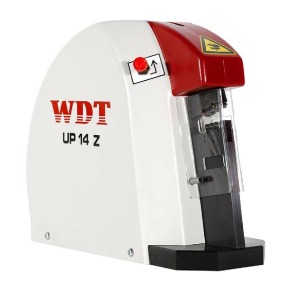
Technische Beschreibung Funktions- und Bedienungselemente Abb. 4.1 Pos. Bezeichnung Pneumatische Crimpmaschine UP 14 Z Fingerschutz Positioniereraufnahme Rückstell-Taster P = Druckluft A = Steuerdruck P2= Druckluft (Fußschalter) Typenschild mit Seriennummer Blackbox Pneumatisches Fußpedal Fußpedal-Schutzhaube BDA UP 14 Z – 03/15 – REV. 0 Page 10 / 71... -
Page 11: Maschinenidentifikation
Maschinenidentifikation Pos. Bezeichnung Maschinentyp Maschinennummer Abb. 4.2 Technische Daten Abmessung: Länge: 300 mm Breite: 125 mm Höhe: 260 mm Gewicht mit Fußpedal: 14,5 kg Betriebsdruckluft: 6 bar Luftverbrauch pro Hub: 6.6 l Crimpkraft bei 6 bar: max. 14 kN Lärmpegel: 73 dB(A) Schutzabdeckung Crimpmaschine... -
Page 12: Rückstelltaster
Rückstelltaster Sind Crimpbacken durch einen Bedienungs- oder Handhabungsfehler oder falsches Einlegen eines Crimpkontaktes blockiert, wird pneumatische Crimpmaschine UP 14 Z wie folgt gelöst: Betätigen des Rückstell-Tasters. Abb. 4.4 Transport und Aufstellung Transport Das Gewicht der Maschine beträgt 13 kg. WARNUNG Tragen Sie beim Transport und beim Aufstellen der pneumatischen Crimpmaschine UP 14 Z geeignete Sicherheitsschuhe. -
Page 13: Inbetriebnahme / Anschließen An Das Druckluftnetz
VORSICHT Verlegen Sie so die Schläuche am Boden, dass sie keine Stolpergefahr bilden. Fußpedal nicht in Verkehrswegen verlegen! Der Zugang zu den Stellteilen der Maschine muss frei gehalten werden. Dies gilt insbesondere für das Fußpedal. Tragen Sie beim Transport und bei der Aufstellung der Maschine geeignete Sicherheitsschuhe. - Page 14 Pneumatischer Fußpedalanschluss 1 mit Schlauch 1 an der Blackbox verbinden (PU Druckluftschlauch Ø 6 / 4 mm). Schlauch P2 der Blackbox mit Anschluss P2 Maschine verbinden Druckluftschlauch Ø 4 / 2,5 mm). Steuerleitung von pneumatischen Fußpedal 4 an Schlauch 4 an der Blackbox verbinden (PU Druckluftschlauch Ø...
-
Page 15: Umrüsten / Montage Wezag Gesenke
Umrüsten / Montage WEZAG Gesenke GEFAHR Es besteht die Restgefahr des Quetschens von Fingern. Versuchen Sie nie in die Gefahrenstelle zu greifen, ohne dass die Maschine sicher von der pneumatischen Versorgung getrennt wurde. Unterbrechen Sie die pneumatische Versorgung, bevor Sie die Schutzabdeckung und das Gesenkpaar auswechseln. - Page 16 Schutzabdeckung montieren: Gesenk mit Positionierer (Abb. 7.2) 1. Schutzabdeckung großer Aussparung montieren und Schrauben befestigen. 2. Positioniereraufnahme 2 montieren und Schraube festziehen. 3. Positionierer auf Positioniereraufnahme 2 stecken. Abb. 7.2 WARNUNG Die große Aussparung der Schutzabdeckung darf nur mit montierter Positioniereraufnahme und aufgestecktem Positionierer verwendet werden.
-
Page 17: Normalbetrieb /Produktionsbetrieb
Normalbetrieb /Produktionsbetrieb GEFAHR Es besteht die Restgefahr des Quetschens von Fingern. Versuchen Sie nie in die Gefahrenstelle zu greifen, ohne dass die Maschine sicher von der pneumatischen Versorgung getrennt wurde. Unterbrechen Sie die pneumatische Versorgung, bevor Sie die Schutzabdeckung und das Gesenkpaar auswechseln. WARNUNG Die pneumatische Crimpmaschine UP 14 Z darf nur in technisch einwandfreiem Zustand sowie sicherheits- und gefahrenbewusst eingerichtet und betrieben werden. -
Page 18: Instandhaltung
Instandhaltung GEFAHR Es besteht die Restgefahr des Quetschens von Fingern. Versuchen Sie nie in die Gefahrenstelle zu greifen, ohne dass die Maschine sicher von der pneumatischen Versorgung getrennt wurde. Unterbrechen Sie die pneumatische Versorgung, bevor Sie die Schutzabdeckung und das Gesenkpaar auswechseln. WARNUNG Der Druckluftanschluss darf eine Schlauchlänge von 1 Meter nicht überschreiten und muss über einen Kupplungsanschluss verfügen. -
Page 19: Wartungsplan
Wartungsplan GEFAHR Es besteht die Restgefahr des Quetschens von Fingern. Versuchen Sie nie in die Gefahrenstelle zu greifen, ohne dass die Maschine sicher von der pneumatischen Versorgung getrennt wurde. Unterbrechen Sie die pneumatische Versorgung, bevor Sie die Schutzabdeckung und das Gesenkpaar auswechseln. WARNUNG Vor Beginn von Wartungs-, Demontage- und Instandhaltungsarbeiten muss die pneumatische Crimpmaschine UP 14 Z sicher von der pneumatischen Versorgung... -
Page 20: Fehlersuche Und Störungsanalyse
Fehlersuche und Störungsanalyse GEFAHR Es besteht die Restgefahr des Quetschens von Fingern. Versuchen Sie nie in die Gefahrenstelle zu greifen, ohne dass die Maschine sicher von der pneumatischen Versorgung getrennt wurde. Unterbrechen Sie die pneumatische Versorgung, bevor Sie die Schutzabdeckung und das Gesenkpaar auswechseln. WARNUNG Vor Beginn von Wartungs-, Demontage- und Instandhaltungsarbeiten muss die Crimpmaschine sicher von der pneumatischen Versorgung getrennt sein. -
Page 21: Außerbetriebnahme, Abbau, Demontage
Außerbetriebnahme, Abbau, Demontage GEFAHR Es besteht die Restgefahr des Quetschens von Fingern. Versuchen Sie nie in die Gefahrenstelle zu greifen, ohne dass die Maschine sicher von der pneumatischen Versorgung getrennt wurde. Unterbrechen Sie die pneumatische Versorgung, bevor Sie die Schutzabdeckung und das Gesenkpaar auswechseln. WARNUNG Vor Beginn von Wartungs-, Demontage- und Instandhaltungsarbeiten muss die pneumatische Crimpmaschine UP 14 Z sicher von der pneumatischen Versorgung... -
Page 22: Ersatzteilliste
Ersatzteilliste 14.1 Explosionszeichnung Abb. 14.1 BDA UP 14 Z – 03/15 – REV. 0 Page 22 / 71... -
Page 23: Stückliste Explosionszeichnung
14.2 Stückliste Explosionszeichnung ARTIKEL- POS.NR. STÜCK ERSATZTEIL BENENNUNG 2481-01001 Bodenplatte 8480-84004 Gummifuss Ø20 2481-01002 Zugplatte, rechts 8481-01509 Zylinderbuchse Ø16/12 x20 Zylinderschraube mit Iskt. M8x25 8480-99137 DIN912 2481-01003 Zugplatte, links 2481-01004 Gesenkplatte 8480-99158 Pass-Scheibe Ø6/20 x0,1 DIN988 8480-99109 Zylinderstift 6h6x50 DIN6325 Zylinderschraube mit Iskt. - Page 24 ARTIKEL- POS.NR. STÜCK ERSATZTEIL BENENNUNG 2480-95014 Ventilwinkel 8480-99172 Scheibe A4,3 DIN125-St verzinkt Zylinderschraube mit Iskt. M3x14 8480-99121 DIN912 1481-14001 Haube komplett mit Bohrungen Linsenschraube mit Iskt. M5x12 8481-02008 (verzinkt-blau) Zylinderschraube mit Iskt. M4x8 8481-01003 DIN7984 1480-89002 Positioniereraufnahme 8550-00008 Linsenschraube mit Iskt. M4x12 1481-01006 Schutzabd.
-
Page 25: Pneumatik Schema
14.3 Pneumatik Schema Abb. 14.2 BDA UP 14 Z – 03/15 – REV. 0 Page 25 / 71... -
Page 26: Stückliste Pneumatik Schema
14.4 Stückliste Pneumatik Schema ARTIKEL- POS.NR. STÜCK ERSATZTEIL BENENNUNG Steckanschluss SISTEM P-gerade 8480-88041 6mm EASY Einschraub-Steckverbinder M5 - Ø 8480-88081 3/2 Wege Ventil 8480-89007 Schott-Steckverbinder Ø4 8480-88106 pneumatisches Mini-Tastventil 8480-88005 Oder Ventil 8480-88086 Y-Steckverbinder Ø4 8480-88072 5/3 Wege Ventil 8480-88089 5/2 Wege Ventil 8480-85002 L-Einschraub-Steckverbinder G1/8 - Ø... - Page 27 Table of Contents Introduction ............................. 28 Product Specification ........................28 Conformity ............................28 Dealing with the Operating Instruction ................... 28 Safety ..............................29 Warning & Safety Precautions in this Operating Instruction ............29 ...
-
Page 28: Introduction
Introduction Product Specification The pneumatic Crimp Machine UP 14 Z is a pneumatic crimp machine for the WEZAG interchangeable crimping system designed as a complete table top unit. With the pneumatic Crimp Machine UP 14 Z the most common terminals on the market can be crimped with the WEZAG interchangeable crimping system. -
Page 29: Safety
Safety Warning & Safety Precautions in this Operating Instruction The following warnings and safety related cautionary notices in the individual chapters alert you to various levels of danger: DANGER Identifies an imminent, serious danger, which, if it is not avoided, will lead to serious injuries or even to death. - Page 30 Tubes must not be damaged. Place the foot pedal on the floor. No other place is allowed. The foot pedal must be movable, so that the operator has the possibility to change his position for ergonomic and production needs. Do not lay the foot pedal in aisles or walk ways. Assure free access to the operating elements of the machine, especially the foot pedal.
-
Page 31: Responsibilities
Realization of crimp connections up to a cable Ø of 50 mm² depending on the terminal design. The pneumatic Crimp Machine UP 14 Z is designed for the use of the WEZAG dies. The pneumatic Crimp Machine UP 14 Z should only be used with the dies specified by WEZAG. It... -
Page 32: Hazardous Areas
Hazardous Areas 1. Hazardous Area: Area of interchangeable crimping dies Person at risk: Operator Type of Hazard: Hand Injuries 2. Hazardous Area: Opened Machine Person at risk: Installation Engineer Type of Hazard: Direct or indirect contact with movable parts of the machine, Hand injuries (cuts from sharp edges) Hand injuries (risk of crushing) Shipment... -
Page 33: Technical Description
Technical Description Operators Guide Fig. 4.1 Item Description Pneumatic Crimp Machine UP 14 Z Safety guard Locator holding fixture Release Button P = compressed air A =control pressure P2 = compressed air (foot pedal) Label with serial number Black box Pneumatic foot pedal Safety cover for foot pedal BDA UP 14 Z –... -
Page 34: Machine Identification
Machine Identification Item Description Machine Type Serial Number Fig. 4.2 Technical Data Dimension: Length overall: 300 mm Width: 125 mm Height: 260 mm Weight with foot pedal: 14,5 kg. Air pressure: max. 6 bar /87 psi Air consumption per stroke: 6.6 l Crimp Force at 6 bar: max. -
Page 35: Release Button
Release Button In case of jammed jaws caused by operation handling errors wrongly placed terminals the jaws can be opened as follows: Press Release Button. Fig. 4.4 Transport and Installation Transport The weight of the pneumatic Crimp Machine UP 14 Z is approx. 13 kg. CAUTION During transport and installation of the machine wear suitable safety shoes. -
Page 36: Commissioning / Connecting To Compressed Air Supply
ATTENTION Place the tubes on the floor so that they do not cause a trip hazard. Do not lay the foot pedal in aisles or walk ways. Assure free access to the operating elements of the machine, especially the foot pedal. During transport and installation of the machine wear suitable safety shoes. - Page 37 Connect pneumatic foot pedal connection 1 with tube 1 of the black box (PU air hose Ø 6 / 4 mm). Connect tube P2 of the black box with pneumatic supply P2 on the machine (PU air hose Ø 4 / 2,5 mm). Connect control cable of the pneumatic foot pedal 4 on tube 4 of the black box.
-
Page 38: Tooling
Tooling DANGER Due to the risk of hand or finger injury, never try to reach into the machine before having assured that the machine is disconnected from the air supply. Disconnect the air supply before changing the safety guard and the dies. CAUTION The pneumatic Crimp Machine UP 14 Z may only be set up and operated in perfect technical condition, observing all the safety regulations and considering any possible... - Page 39 Installation of safety guard: Die set with locator (Fig. 7.2) 1. Install the safety guard 3 with the larger opening and tighten the screws. 2. Install the locator holding fixture 2 and tighten the screw. 3. Put the locator on the locator holding fixture 2.
-
Page 40: Normal Operation / Production Cycle
Normal Operation / Production Cycle DANGER Due to the risk of hand or finger injury, never try to reach into the machine before having assured that the machine is disconnected from the air supply. Disconnect the air supply before changing the safety guard and the dies. CAUTION The pneumatic Crimp Machine UP 14 Z may only be set up and operated in perfect technical condition, observing all the safety regulations and considering any possible... -
Page 41: Maintenance
Maintenance DANGER Due to the risk of hand or finger injury, never try to reach into the machine before having assured that the machine is disconnected from the air supply. Disconnect the air supply before changing the safety guard and the dies. CAUTION The compressed air connection tube must not be longer than 1 m and has to have a coupling connection. -
Page 42: Daily
9.1.1 Daily Visual inspection of the pneumatic Crimp Machine UP 14 Z. Check air pressure (max. 6 bar.) of the house installation (manometer not in the scope of the delivery). Check oil-level of service unit of the house installation (not in the scope of the delivery). 9.1.2 Monthly Lubricating all moving levers and bolts. -
Page 43: Removal From Service, Demounting, Disassembly
Removal from Service, Demounting, Disassembly, DANGER Due to the risk of hand or finger injury, never try to reach into the machine before having assured that the machine is disconnected from the air supply. Disconnect the air supply before changing the safety guard and the dies. CAUTION Before starting maintenance, disassembly or repair work, the crimping machine must be disconnected from air supply. -
Page 44: Exploded View Drawing, Spare Part List
Exploded View Drawing, Spare Part List 14.1 Exploded View Drawing Fig. 14.1 BDA UP 14 Z – 03/15 – REV. 0 Page 44 / 71... -
Page 45: Parts List Exploded View Drawing
14.2 Parts List Exploded View Drawing Item.-No. WDT-P/N Spare Part Description 2481-01001 Bottom plate 8480-84004 Rubber foot Ø20 2481-01002 Plate, right 8481-01509 Cylinder liner Ø16/12 x20 8480-99137 Hex. Socket screw M8x25 DIN912 2481-01003 Plate, left 2481-01004 Die plate 8480-99158 Adjusting washer Ø6/20 x0,1 DIN988 8480-99109 Cylinder bolt 6h6x50 DIN6325 8481-01001... - Page 46 Item.-No. WDT-P/N Spare Part Description 8480-99121 Hex. Socket screw M3x14 DIN912 1481-14001 Cover complete with holes Lens head screw M5x12 (galvanized- 8481-02008 blue) 8481-01003 Hex. Socket screw M4x8 DIN7984 1480-89002 Locator holding fixture 8550-00008 Lens head screw M4x12 1481-01006 Safety Guard complete. CK100 / CS30 5480-88002 Label "Hinweis Fingerschutz"...
-
Page 47: Pneumatic Diagram
14.3 Pneumatic Diagram Fig. 14.2 BDA UP 14 Z – 03/15 – REV. 0 Page 47 / 71... -
Page 48: Parts List Pneumatic
14.4 Parts List Pneumatic Item.-No. WDT-P/N Spare Part Description Plug connection SISTEM P-straight 8480-88041 6mm EASY Screw in connector M5 - Ø 4mm 8480-88081 3/2 pneumatic valve 8480-89007 Schott-connector Ø4 8480-88106 pneumatic Mini-Touch Valve 8480-88005 Oder Valve 8480-88086 Y-Connector Ø4 8480-88072 5/3 pneumatic valve 8480-88089... - Page 49 Transport ............................57 Mise en Place ..........................57 Mise en Service / Raccordement au Système d’Air Comprimé ............. 58 Assemblage des Matrices WEZAG ......................60 Utilisation Normale/Exploitation ......................62 Entretien ..............................63 ...
-
Page 50: Introduction
La Machine pneumatique à Sertir UP 14 Z est une machine pneumatique pour le WEZAG système à sertir, conceptionée comme machine à table. La Machine pneumatique à Sertir UP 14 Z est prévue pour le sertissage de la plupart des cosses à sertir avec le WEZAG système à sertir interchangeable. -
Page 51: Sécurité
Sécurité Indications Relatives à la Sécurité figurant dans le Monde d’Emploi Les indications suivantes relatives à la sécurité et figurant dans chacun des chapitres du manuel attirent l'attention sur les dangers de différents degrés de gravité. DANGER Identifie un danger imminent qui, s‘il n’est pas évité, a pour conséquence des blessures graves ou de mort. - Page 52 Connectez la machine au système d’air comprimé avec la tube livré (longueur :1 m) Déplacez les tuyaux sur le sol de telle façon à empêcher tout risque de trébucher. Les tuyaux ne doivent pas être endommagés. Posez la commande à pied pneumatique sur le sol. Tout positionnement de la commande à...
-
Page 53: Responsabilités
La Machine pneumatique à Sertir UP 14 Z est conçue pour utilisation avec les matrices WEZAG. La Machine pneumatique à Sertir UP 14 Z doive être uniquement équipée de matrices de sertissage conformes aux spécifications de WEZAG. La Machine pneumatique à... -
Page 54: Zones De Danger
Zones de Danger 1. Zone de danger: Zone des matrices interchangeables Personne en danger: Utilisateur Type de danger : Danger d’écrasement 2. Zone de danger : Machine ouverte Personne en danger: Technicien d’installation Type de danger: Contact direct ou indirect avec des pièces desserrées de la machine. -
Page 55: Description Technique
Description Technique Eléments de Fonction et d’Utilisation Fig. 4.1 Pos . Description Machine pneumatique à Sertir UP 14 Z Protection pour les doigts Raccord des positionneurs L’Interrupteur d’Arrêt P = Air comprimé A = Pression de commande P2 = Air comprimé (commande à pied) Plaque d’identification aves numéro de série Boîte noire Commande à... -
Page 56: Plaque D'indentification
Plaque d’indentification Pos. Description Type de Machine Numéro de Série Fig. 4.2 Données Techniques Dimension: Longueur: 300 mm Largeur: 125 mm Hauteur: 260 mm Poids avec commande: 14,5 kg Air comprimé: 6 bar Consommation d'air par cycle: 6.6 l Force de sertissage 6 bar: max. -
Page 57: L'interrupteur D'arrêt
L’Interrupteur d’Arrêt Quand les mâchoires restent coincées à cause d'un maniement ou manœuvre incorrect ou faux placement de la cosse, appuyez l’interrupteur d’arrêt mâchoires s'ouvrent. Appuyez l’interrupteur d’arrêt. Fig. 4.4 Transport et Mise en Place Transport Le poids total de la Machine pneumatique à Sertir UP 14 Z est de 13 kg. AVERTISSEMENT Portez des chaussures de sécurité... -
Page 58: Mise En Service / Raccordement Au Système D'air Comprimé
ATTENTION Déplacez les tuyaux sur le sol de telle façon à empêcher tout risque de trébucher. Ne posez pas la commande à pied sur des voies de circulation. Il faut garantir un accès dégagé aux éléments de commande de la machine. Ceci vaut particulièrement pour la commande à... - Page 59 Reliez le raccord 1 de la commande à pied pneumatique avec le tuyau 1 de la boîte noire (PU tuyau Ø 6/4 mm). Connectez le tuyau P2 de la boîte noire avec le raccord P2 à la machine (PU tuyau Ø...
-
Page 60: Assemblage Des Matrices Wezag
Assemblage des Matrices WEZAG DANGER Il existe un risque résiduel d’écrasement des doigts. N’essayez jamais de toucher la zone dangereuse sans que la machine soit déconnectée en toute sécurité d´approvisionnement pneumatique. Débranchez l´alimentation pneumatique avant de remplacer la protection de sécurité... - Page 61 Assemblage de la protection the sécurité: Matrices avec positionneur (Fig. 7.2) 1. Assemblez la protection de sécurité 3 avec la grande ouverture. 2. Assemblez le raccord des positionneurs 2 et serrez la vis. 3. Enfilez le positionneur au raccord des positionneurs 2.
-
Page 62: Utilisation Normale/Exploitation
Utilisation Normale/Exploitation DANGER Il existe un risque résiduel d’écrasement des doigts. N’essayez jamais de toucher la zone dangereuse sans que la machine soit déconnectée en toute sécurité d´approvisionnement pneumatique. Débranchez l´alimentation pneumatique avant de remplacer la protection de sécurité et le couple des matrices. AVERTISSEMENT La Machine pneumatique à... -
Page 63: Entretien
Entretien DANGER Il existe un risque résiduel d’écrasement des doigts. N’essayez jamais de toucher la zone dangereuse sans que la machine soit déconnectée en toute sécurité d´approvisionnement pneumatique. Débranchez l´alimentation pneumatique avant de remplacer la protection de sécurité et le couple des matrices. AVERTISSEMENT Le tube de la connexion de l’air comprimé... -
Page 64: Maintenance
Maintenance DANGER Il existe un risque résiduel d’écrasement des doigts. N’essayez jamais de toucher la zone dangereuse sans que la machine soit déconnectée en toute sécurité d´approvisionnement pneumatique. Débranchez l´alimentation pneumatique avant de remplacer la protection de sécurité et le couple des matrices. AVERTISSEMENT La machine à... -
Page 65: Recherche D'erreurs Et Analyse De Problèmes
Recherche d’Erreurs et Analyse de Problèmes DANGER Il existe un risque résiduel d’écrasement des doigts. N’essayez jamais de toucher la zone dangereuse sans que la machine soit déconnectée en toute sécurité d´approvisionnement pneumatique. Débranchez l´alimentation pneumatique avant de remplacer la protection de sécurité... -
Page 66: Mise Hors Service, Démontage
Mise hors Service, Démontage DANGER Il existe un risque résiduel d’écrasement des doigts. N’essayez jamais de toucher la zone dangereuse sans que la machine soit déconnectée en toute sécurité d´approvisionnement pneumatique. Débranchez l´alimentation pneumatique avant de remplacer la protection de sécurité... -
Page 67: Diagramme Et Liste Des Pièces Détachées
Diagramme et Liste des Pièces Détachées 14.1 Diagramme des Pièces Détachées Fig. 14.1 BDA UP 14 Z – 03/15 – REV. 0 Page 67 / 71... -
Page 68: Liste Des Pièces
14.2 Liste des Pièces Pièces Pos.-Nr. Pièces WDT-P/N Description Détachée 2481-01001 Plaque de fond 8480-84004 Pied caoutchouté Ø20 2481-01002 Tension plaque à droite 8481-01509 Douille de Cylindre Ø16/12 x20 Vis à tête cyl. avec 6-p. M8x25 8480-99137 DIN912 2481-01003 Tension plaque à gauche 2481-01004 Plaque des Matrices Rondelle d’ajustage Ø6/20x0,1... - Page 69 Pièces Pos.-Nr. Piéces WDT-P/N Description Détachée 2480-82038 Angle de l’interrupteur Vis à tête cyl. avec 6-p M5x12 8480-81039 DIN912 2480-95014 Angle de la vanne 8480-99172 Bague A4,3 DIN125-St zinguée Vis à tête cyl. avec 6-p M3x14 8480-99121 DIN912 1481-14001 Capot complet avec des alésages 8481-02008 Vis avec 6-p M5x12 (zinguée-bleu) Vis à...
-
Page 70: Schéma Pneumatique
14.3 Schéma pneumatique Fig. 14.2 BDA UP 14 Z – 03/15 – REV. 0 Page 70 / 71... -
Page 71: Liste Des Pièces Détachées Schéma Pneumatique
14.4 Liste des Pièces Détachées Schéma Pneumatique Pièces Pos.-Nr. Pièces WDT-P/N Description Détachée Borne à fiche SISTEM P-droite 6mm 8480-88041 EASY 8480-88081 Visser connecteur M5 - Ø 4mm 8480-89007 3/2 Vanne pneumatique 8480-88106 Schott-connecteur Ø4 8480-88005 Mini- vanne tactile pneumatique 8480-88086 Oder vanne 8480-88072...