Table des Matières

Publicité

Les langues disponibles

Les langues disponibles

Liens rapides

Cube
®
TouchDisplay
Gebruikershandleiding
Manuel d'instruction
pour l'utilisateur
Bedienungsanleitung
User Manual
Software version 11035.7.2.0/8.0.0

Publicité

Table des Matières
loading

Sommaire des Matières pour Renson Cube TouchDisplay

  • Page 1 Cube ® TouchDisplay Gebruikershandleiding Manuel d’instruction pour l’utilisateur Bedienungsanleitung User Manual Software version 11035.7.2.0/8.0.0...
  • Page 2 Proficiat met uw aankoop van de TouchDisplay voor het Cube ventilatiesysteem! Inhoudstafel 1 • Professioneel product ...................... 2 • Onderdelen ........................3 • Verpakking en bescherming van het milieu ............... 4 • Veiligheidsvoorschriften ....................5 • Montage en aansluiting ....................6 •...
  • Page 3 • Binnenluchtkwaliteit te meten: Een unieke bediening met kleurenscherm geeft de bewoners, op elk moment van de dag, informatie over de binnenluchtkwaliteit van de leefruimte en toont hoe het RENSON ventila- ®...
  • Page 4 Verwijder het afgedankte apparaat dan ook nooit met het gewone afval. Kies er voor om het op een milieuvriendelijke manier af te voeren. 4 • Veiligheidsvoorschriften Het toestel in deze verpakking voldoet aan de voorgeschreven CE-veiligheidsvoorschriften. RENSON Ventilation nv ® IZ 2 Vijverdam...
  • Page 5 Bij het niet opvolgen van deze veiligheidsvoorschriften, waarschuwingen, opmerkingen en instructies kan dit leiden tot schade aan het apparaat of tot persoonlijk letsel. Hiervoor kan RENSON NV niet verantwoordelijk gesteld worden. ® – Zorg ervoor dat de elektrische voeding overeenstemt met 230V, 1 fase, 50Hz.
  • Page 6 Plaats de TouchDisplay in een storingsvrije omgeving, zodat het RF-signaal goed kan uitge- stuurd/ontvangen worden. De TouchDisplay kan enkel gebruikt worden in combinatie met een RENSON Cube ®...
  • Page 7 Kabelaansluiting ➊ ➊ De installatie en elektri- sche aansluiting van de verschillende componenten mag enkel gebeuren door bevoegd personeel overeenkomstig de geldende Min. 2 x 0,75 mm veiligheidsmaatregelen. = 1 A Achteraanzicht ➊ 50Hz 230V AC ±10% Netvoeding...
  • Page 8 Montage De TouchDisplay dient bij voorkeur gemonteerd te worden in een inbouwdoos. De inbouwdoos moet een voldoende inbouwdiepte hebben (min. 47mm). Zijaanzicht Vooraanzicht 44,5 16,7 69,2 50,7 Zorg ervoor dat de inbouwdoos voorzien is van 2 schroefgaten, om de TouchDisplay op vast te schroeven.
  • Page 9 Voorbeeld van enkelvoudige montage (enkele inbouwbehuizing): Als laatste klikt u het afdekplaatje rond de TouchDisplay. Informeer u in de vakhandel voor het desbetreffende afdekplaatje (merken die een passend formaat aanbieden zijn vb. Niko, BTicino Light). 11:38 Positioneer de draadantenne volgens de figuur.
  • Page 10 6 • Linken TouchDisplay met ventilatorunit Alvorens een TouchDisplay bediening in gebruik kan worden genomen, dient de bediening eerst individueel met de ventilatorunit gelinkt te worden. Eenmaal de link is uitgevoerd, is de bediening klaar voor gebruik. Bij aansluiting op het net, verschijnt het scherm waarop de dag en de klok moet worden ingesteld.
  • Page 11 Druk op de printplaat van de Cube ventilatorunit kort op het knopje KNX / LINK. De bovenliggende groene LED gaat nu knipperen. Druk vervolgens op van de TouchDisplay. Er verschijnt een extra lijntje onderaan de display: “Linking”. 0-10V Fan control Main 230V~ XVKS Sensoren Fan power 230V~...
  • Page 12 7 • Aan de slag met de TouchDisplay Ventilatiemode Huidig CO -gehalte Huidige ventilatiestand (locatie TouchDisplay) Knopjes In de handleiding worden 11:38 deze toetsen beschreven als ▼ ▼ Programmapunt Klok Aanduiding CO -gehalte: ≥ 1850 ppm 1500 ppm ≤ CO ≤...
  • Page 13 7.1 • Ventilatiemodes Hoofdmodes Automatische mode Het ventilatiesysteem volgt een vooraf geprogrammeerd ventielatiepro- gramma. Indien er echter een verhoging van de relatieve vochtigheid, aanwezigheid of CO waargenomen wordt, zal het ventilatieniveau 11:38 automatisch aangepast worden. Manuele mode U kiest zelf de ventilatie-intensiteit (level 1 -4). In tegenstelling tot de ‘automatische stand’...
  • Page 14 7.1.1 • Veranderen tussen hoofdmodes Door kort (< 1sec) op te drukken worden de verschillende hoofdmodes doorlopen. < 1 sec. < 1 sec. 11:38 11:38 Automatische mode Manuele mode Opmerkingen: • De ventilatorunit volgt steeds de programma-instelling van de TouchDisplay. Indien u een andere ventilatieregeling wenst, kan u de ventilatiemode manueel aanpassen.
  • Page 15 Nevenmode Boost Mode Tijdens de boostmode wordt er geventileerd op de maximale capaciteit. 11:38 7.1.2 • Activeren van nevenmode Vanuit elke hoofdmode kan men overschakelen naar de nevenmode. • U kan het systeem in Boost mode plaatsen door lang op ▼ te drukken. •...
  • Page 16 7.2 • Bijbedieningen Een bijkomende bediening kan vanop afstand de TouchDisplay tijdelijk overheersen. Een bijkomende bediening is bijv. de Timerbediening. • Wanneer de Timerbediening geactiveerd wordt, wordt tijdelijk de TouchDisplay vergrendeld. Dit wordt weergegeven door een sleutel linksboven op de display. Na afloop van de timer van de Timerbediening wordt de TouchDisplay terug vrijgegeven.
  • Page 17 7.3 • Instellingen • U komt in het USER MENU terecht door: 3 sec op de knop te drukken kort op ▲ ▼ te drukken 11:38 11:38 • Met ▲ ▼ kan u overgaan tussen de verschillende USER MENU’s. Er is keuze uit volgende USER menus: PROGRAM (zie 7.3.1): instellen dag-, week- of weekendprogramma;...
  • Page 18 7.3.1 • Programma instelling Met het user menu PROGRAM kan u de programmapunten (➀ - ➇) programmeren volgens uw persoonlijke wensen. De schakelmomenten zijn de tijdstippen waarop u wilt dat het systeem op een andere ventila- tiemode gaat ventileren. Voorbeeld van een in te stellen programma: Maandag, dinsdag, donderdag en vrijdag Tussen 06:30 en 08:30 L3 Tussen 08:30 en 12:00 L1...
  • Page 19 ▲ ▼ Door gelijktijdig op drukken, keert u terug naar het Het instellen van een eigen programma: vorige menu. Wijzigingen worden dan niet opgeslagen. ➊ • Selecteer hiervoor het USER MENU – PROGRAM en druk kort op ➋ • Met ▲...
  • Page 20 ➍ • De uuraanduiding licht nu op. ▲ ▼ kan u het gewenste uur instellen. bevestigt u. ➎ • De minuutaanduiding licht nu op. ▲ ▼ kan u de gewenste minuten instellen. bevestigt u. • De ventilatiemode licht nu op. kan de ventilatiemode van het programma- ▲...
  • Page 21 PROGRAM • U kan het ingestelde ventilatieprogramma steeds opvragen door in het USER MENU - PROGRAMMA INSTELLING, op het scherm van de periode, gedurende 3 sec. op de drie knopjes MO-SU tegelijk te drukken. Legende: Voorbeeld: 00:00 23:59 maandag dinsdag woensdag donderdag vrijdag...
  • Page 22 Wanneer het USER MENU – CLOCK ver- 7.3.2 • Dag- en klokinstelling vroegd wordt verlaten (door lang op ▲ ▼ drukken of te drukken) worden ➊ de veranderingen niet opgeslagen. U komt terug in het USER MENU. • Met het USER MENU - CLOCK kunnen de huidige dag en tijd ingesteld worden.
  • Page 23 • Selecteer het USER MENU - DISPLAY en druk kort op ➋ • Active Time licht op. Dit is de tijd waarna de display in stand-by gaat. Standaard is deze ingesteld op 5 minuten. In stand-by wordt het RENSON -logo weergegeven. ® Druk op om deze tijdsduur aan te passen.
  • Page 24 ➍ • Door op ▼ te drukken licht Brightness Active op. Dit is de lichtintensiteit van de display bij bediening. Standaard is deze ingesteld op 80%. Druk op om de lichtintensiteit aan te passen. ➎ ▲ ▼ kan een waarde tussen 25% en 100% ingegeven worden.
  • Page 25 ➐ ▲ ▼ kan een waarde tussen 0% en 40% ingegeven worden. Bevestig en bewaar de ingestelde waarde door op drukken. ➑ • Door op ▼ te drukken licht Language op. Dit is de taal die gebruikt wordt in het USER MENU. Standaard is deze ingesteld op Engels.
  • Page 26 8 • Toepassing met 2 of meerdere TouchDisplay bedieningen De ventilatorunit kan bediend worden met meerdere TouchDisplay bedieningen. De hoofdbediening wordt in de keuken of woonkamer geplaatst, afhankelijk van de situatie (zie rubriek 5. “Montage en aansluiting”). De andere bediening(en), nevenbediening(en) genoemd, kunnen in een locatie geplaatst worden naar keuze.
  • Page 27 8.1 • Linken TouchDisplay met ventilatorunit De TouchDisplay dient eerst met de ventilatorunit gelinkt te worden indien dit nog niet gebeurd is. Volg hiertoe de stappen beschreven in rubriek 6: ‘Linken TouchDisplay met ventilatorunit’. 8.2 • Instellen als hoofd- of nevenbediening Afhankelijk van de functie van de de TouchDisplay kan deze ingesteld worden als hoofd- of nevenbediening en/of als repeater.
  • Page 28 ➋ • Selecteer “main controller” met ➌ • Met behulp van kan u er voor kiezen de TouchDis- ▲ ▼ play als nevenbediening (= Main Controller: OFF) in te stellen. Bevestig uw keuze door op te drukken. U komt terug in het INSTALLER MENU –...
  • Page 29 8.2.2 • Instellen van de TouchDisplay als repeater Het instellen van de TouchDisplay als repeater is nodig wanneer de hoofdbediening zich te ver van de ventilatorunit bevindt. Het is immers mogelijk dat een signaal gegenereerd door de hoofdbediening de ventilatorunit niet bereikt. Door een extra TouchDisplay dichter bij de ventilatorunit te plaatsen en als repeater in te stellen, zal het uitgezonden signaal van de hoofdbediening doorgegeven worden aan de repeater.
  • Page 30 ➌ • Met behulp van ▲ ▼ kan u er voor kiezen de Touch- Display al dan niet als repeater (KNX Repeater: ON) in te stellen. Bevestig uw keuze door op te drukken. U komt terug in het INSTALLER MENU – DEVICE SETTINGS. •...
  • Page 31 ➊ • Roep het INSTALLER MENU op (cfr. beschrijving onder rubriek 8). Selecteer - CO -THRESHOLD en druk kort op ➋ • De grenswaarde voor de CO -concentratie licht op. U kunt hier een waarde tussen 450 ppm en 2000 ppm ingeven met behulp van ▲...
  • Page 32 10 • Probleemoplossing 10.1 • Herstarten na stroomonderbreking Wanneer de TouchDisplay opnieuw wordt ingeschakeld (bijv. na stroompanne): ➊ • Volgend scherm verschijnt waarop de dag en de klok wordt weergegeven. • De instelling dient opnieuw te gebeuren. Volg hiervoor de stappen beschreven onder stap 2 rubriek 7.3.2.
  • Page 33 Opmerkingen: • Als de verbinding niet opnieuw gerealiseerd wordt, zal “Fan Not Ready” blijvend op het scherm vertoond worden. – Als er geen communicatie is met de ventilatorunit, wordt “Lost Communication With Fan” weergegeven na 5 minuten: – Als de ventilatorunit in ‘error’ is, wordt de Fan Error Log weergegeven. Indien het probleem zich blijft voordoen, contacteer dan uw installateur.
  • Page 34 10.2 • Andere Indien de verbinding met de ventilatorunit verbroken is, verschijnt volgende foutmelding: Het systeem zal zelf proberen de verbinding te herstellen. Enkel na meerdere onsuccesvolle pogingen zal het error-scherm blijven staan. Contacteer in dit geval uw installateur. 11 • Reiniging en onderhoud Specifiek onderhoud is niet vereist voor dit toestel.
  • Page 35 Maak vermelding van het garantienummer op de sticker achteraan de handleiding. Laat defecte onderdelen enkel vervangen door RENSON vervangstukken. ® Enkel dan bent u zeker dat ze ten volle voldoen aan de eisen die RENSON qua veiligheid ® stelt. Door ondeskundig uitgevoerde reparaties kunnen er onvoorziene risico's ontstaan voor de gebruiker.
  • Page 36: Table Des Matières

    Félicitations pour votre achat de la commande TouchDisplay pour le système de ventilation Cube ! Table des matières 1 • Produit professionnel ....................2 • Eléments ........................3 • Emballage et protection de l’environnement ..............4 • Prescriptions de sécurité ....................
  • Page 37: Produit Professionnel

    Une commande unique avec écran couleur procure à l'utilisateur à tout moment de la journée l'information concernant la qualité de l'air intérieur de la pièce et montre comment le système de ventilation de RENSON améliore la qualité de l'air intérieur.
  • Page 38: Emballage Et Protection De L'environnement

    à la sécurité de l’appareil. Ne jetez jamais l’appareil usé à la poubelle ordinaire. Choisissez de l’éliminer de manière écologique. 4 • Prescriptions de sécurité L’appareil dans cet emballage répond aux normes CE. RENSON Ventilation nv ® IZ 2 Vijverdam Maalbeekstraat 10...
  • Page 39 • Lors de l’installation, tenez toujours compte des prescriptions de sécurité suivantes. Le non-respect des prescriptions de sécurité, avertissements, et instructions peut entraîner des dégâts corporels ou à l’appareil. Dans ce cas, RENSON NV ne peut pas être tenu pour responsable. ®...
  • Page 40: Montage Et Raccordement

    Placez le TouchDisplay dans un environnement libre de perturbations, de sorte que le signal RF puisse être bien émis/réceptionné. Le TouchDisplay ne peut être utilisé qu’en combinaison avec l’unité de ventilation Cube (Compact) de RENSON ® Avant de monter et d'installer le TouchDisplay: •...
  • Page 41 Raccordement électrique ➊ ➊ L’installation et le raccorde- ment électrique des différents éléments peuvent uniquement se faire par un service compé- tent selon les règlements de sécurité. Min. 2 x 0,75 mm = 1 A ➊ Vue arrière 50Hz 230V AC ±10% Alimentation secteur...
  • Page 42 Montage Le TouchDisplay doit être monté de préférence dans un boîtier d’encastrement. Le boîtier doit avoir une épaisseur d’encastrement suffisante (min. 47mm). Vue latérale Vue de face 44,5 16,7 69,2 50,7 Veillez à ce que le boîtier comporte 2 trous de vis, pour y fixer le TouchDisplay. Le boîtier d’encastrement doit être placé...
  • Page 43 Exemple de montage simple (boîtier d’encastrement simple) : En dernier lieu vous clippez la plaque de recouvrement autour du TouchDisplay. Informez vous auprès des magasins spécialisés pour la plaque de recouvrement adéquate (les marques qui proposent le format adapté sont par ex. Niko, BTicino Light). 11:38 Positionnez l'antenne comme indiqué...
  • Page 44: Relier Le Touchdisplay À L'unité De Ventilation

    6 • Relier le TouchDisplay à l’unité de ventilation Avant d’utiliser une commande TouchDisplay il faut d’abord relier la commande individuellement à l’unité de ventilation. Une fois le lien effectué, on peut utiliser la commande. Lors du branchement sur le réseau, l’écran apparaît sur lequel le jour et l’heure doivent être réglés.
  • Page 45 Appuyez légèrement sur le circuit imprimé du Cube sur la touche KNX / LINK. La LED supérieure verte va se mettre à clignoter. Appuyez ensuite sur la touche TouchDisplay. Une ligne supplémentaire apparaît en bas de l’écran : “Linking” 0-10V Fan control Main 230V~ XVKS Sensoren Fan power 230V~...
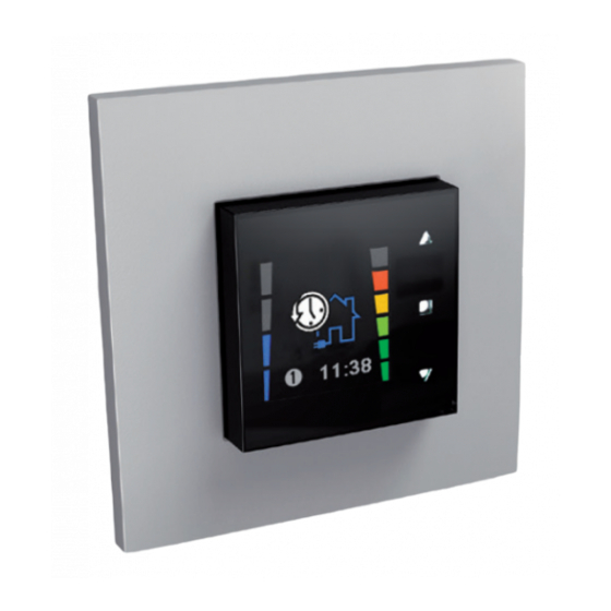
  • Page 46: Utilisation Du Touchdisplay

    7 • Utilisation du TouchDisplay Mode de ventilation Concentration actuelle Situation actuelle de CO (emplacement de la ventilation TouchDisplay) Touches Dans le manuel, ces touches 11:38 sont décrites comme suit : ▼ ▼ Point de la programmation Horloge Indication de la concentration de CO ≥...
  • Page 47: Modes De Ventilation

    7.1 • Modes de ventilation Modes principaux Mode automatique Le système de ventilation suit un programme de ventilation préprogrammé. S’il y a une augmentation de l’humidité relative, ou de la présence de CO , le niveau de ventilation va être 11:38 automatiquement adapté.
  • Page 48: Changement Des Modes Principaux

    7.1.1 • Changement des modes principaux En appuyant brièvement (< 1sec) sur on sélectionne les différents modes principaux. < 1 sec. < 1 sec. 11:38 11:38 Mode automatique Mode manuel Remarques • L’unité de ventilation suit toujours la programmation établie par le TouchDisplay. Si vous voulez un autre réglage de ventilation, vous pouvez adapter le mode de ventilation manuellement.
  • Page 49: Activer Le Mode Secondaire

    Mode secondaire Boost Mode Pendant le mode Boost on ventile à capacité maximum. 11:38 7.1.2 • Activer le mode secondaire On peut activer le mode secondaire au départ de n'importe quel mode principal. • Vous pouvez mettre le système en mode Boost en appuyant languement sur ▼. •...
  • Page 50: Commandes

    7.2 • Commandes annexes Une commande complémentaire à distance peut temporairement ignorer le TouchDisplay. Les commandes complémentaires sont par exemple la commande minuterie. • Lorsque la commande minuterie est activé, on verrouille temporairement le TouchDisplay. Ceci est représenté par une clé en haut à gauche de l’écran. Après le déroulement de la minuterie de la commande minuterie la commande TouchDisplay est à...
  • Page 51: Réglages

    7.3 • Réglages • Vous entrez dans le MENU UTILISATEUR en : Appuyant 3 sec sur la touche Brièvement sur les touches ▲ ▼ 11:38 11:38 • Avec les touches ▲ ▼ vous pouvez changer entre les différents MENUS. Il y a le choix entre plusieurs menus : PROGRAM (voir 7.3.1) : régler la programmation par jour, semaine ou week-end jusqu’à...
  • Page 52: Réglage Du Programme

    7.3.1 • Réglage du programme Avec le menu utilisateur PROGRAMME vous pouvez programmer les points de programmation (➀ - ➇) selon vos désirs. Les moments de transition sont les modes pendant lesquels vous voulez que le système fonctionne sur un autre mode de ventilation. Exemple d’un programme à...
  • Page 53 Si vous quittez l’écran en appuyant ▲ ▼ , les modifications ne Etablir soi-même son propre programme : sont pas sauvegardées. ➊ • Selectionnez le MENU UTILISATEUR – PROGRAM et appuyez brièvement sur ➋ • Avec les touches ▲ ▼ la période à...
  • Page 54 ➍ • L'indication de l’heure s’allume maintenant. Avec ▲ ▼ vous pouvez régler l’heure souhaitée. Vous confirmez avec ➎ • L'indication des minutes s’allume. Avec ▲ ▼ vous pouvez régler les minutes souhaitées. Vous confirmez avec • Ensuite le mode de ventilation s’allume. Avec ▲...
  • Page 55 PROGRAM • Vous pouvez toujours consulter le programme de ventilation établi en allant dans le MENU UTILISATEUR – REGLAGE DU PROGRAMME et en appuyant 3 secondes sur les trois touches MO-SU simultanément. Légende: Exemple : 00:00 23:59 lundi mardi mercredi jeudi vendredi samedi...
  • Page 56: Réglage Du Jour Et De L'heure

    Si vous quittez le MENU UTILISATEUR – 7.3.2 • Réglage du jour HORLOGE (en appuyant longuement sur et de l’heure ▲ ▼ , ou ) les changements ne sont pas enregistrés. Vous revenez au MENU UTILISATEUR. ➊ • Avec le MENU UTILISATEUR - HORLOGE vous pouvez régler le jour et l’heure de manière précise.
  • Page 57: Réglage De L'écran

    ➋ • Temps actif s’allume. C’est la période après laquelle le TouchDisplay se met en position stand-by. Celle-ci est réglée en standard à 5 minutes. En position stand-by le logo de RENSON apparaît. ® Appuyez sur pour adapter cette période.
  • Page 58 ➍ • En appuyant sur la touche ▼ , luminosité active s’éclaire. Il s’agit de l’intensité de luminosité de l’écran pendant la commande. Celle-ci est réglée en standard sur 80 %. Appuyez sur la touche pour adapter l’intensité de la lumière.
  • Page 59 ➐ Vous pouvez donner une valeur entre 0 % et 40 % à l’aide des touches ▲ ▼ Confirmez et sauvegardez la valeur réglée en appuyant sur la touche ➑ • En appuyant sur la touche ▼ , la fonction Langue s’allume. C’est la langue qui est utilisée dans le MENU UTILISATEUR.
  • Page 60: Application Avec 2 Ou Davantage De Commandes Touchdisplay

    8 • Application avec 2 ou davantage de commandes TouchDisplay L’unité de ventilation peut être commandée par plusieurs commandes TouchDisplay. La commande principale est placée dans la cuisine ou le living, selon la situation (voir rubrique 5 “montage et raccordement”). L’autre ou les autres commandes, appelées commandes annexes peuvent être placées dans un endroit au choix.
  • Page 61: Relier Le Touchdisplay À L'unite De Ventilation

    8.1 • Relier le TouchDisplay à l’unite de ventilation Le TouchDisplay doit être d’abord relié à l’unité de ventilation si ce n’est pas encore le cas. Suivez pour cela les étapes décrites dans la rubrique 6 : “Relier le TouchDisplay à l’unité de ventilation”.
  • Page 62 ➋ • Sélectionnez “Main Controller” avec la touche • A l’aide des touches ▲ ▼ vous pouvez choisir de ➌ programmer le TouchDisplay en tant que commande annexe (= Main controller : OFF). Confirmez votre choix en appuyant sur la touche .
  • Page 63: Réglage Du Touchdisplay En Tant Que Réémetteur

    8.2.2 • Réglage du TouchDisplay en tant que réémetteur La programmation du TouchDisplay en tant que réémetteur est nécessaire lorsque la commande principale se trouve trop loin de l’unité de ventilation. Il est en effet possible qu’un signal généré par la commande principale n’atteigne pas l’unité de ventilation. En plaçant un touchDisplay supplémentaire plus près de l’unité...
  • Page 64: Programmer La Valeur Seuil De Co

    ➌ • Avec l’aide des touches ▲ ▼ vous pouvez choisir de programmer le TouchDisplay en tant que réémetteur ou non (KNX Repeater : ON). Confirmez votre choix en appuyant sur . Vous revenez dans le MENU INSTALLATEUR – DEVICE SETTINGS •...
  • Page 65 ➊ • Sélectionnez le MENU INSTALLATEUR comme décrit sous la rubrique 8 Sélectionnez le MENU INSTALLATEUR - CO THRESHOLD et appuyez brièvement sur ➋ • La valeur seuil de la concentration de CO s’allume. Vous pouvez introduire une valeur entre 450 ppm et 2000 ppm au moyen des touches ▲...
  • Page 66: Solutions Des Problèmes

    10 • Solutions des problèmes 10.1 • Redémarrer après une coupure de courant Lorsque le TouchDisplay est rebranché à nouveau (par ex. après une panne de courant) ➊ • Cet écran apparaît sur lequel le jour et l’heure sont indiqués. Il faut les reprogrammer.
  • Page 67 Remarque: • Si la connexion n’est pas réalisée à nouveau, l’écran va continuer à afficher “Fan Not Ready”. – S’il n’y a pas de communication avec l’unité de ventilation, le message “Lost Communication With Fan” va s’afficher après 5 minutes: –...
  • Page 68: Divers

    10.2 • Divers Si la connexion avec l’unité de ventilation est interrompue, la mention d’erreur suivante apparaît : Le système va essayer de rétablir la liaison. Après plusieurs essais infructueuses, l'ecran d'erreur va apparaître. Contactez votre installateur. 11 • Nettoyage et entretien Il n’y a pas d’entretien spécifique pour cet appareil.
  • Page 69: Réparations

    En cas de panne, prenez contact avec votre installateur RENSON ® Mentionnez toujours le numéro de garantie qui se trouve sur l'auto-collant à l'arrière du manuel. Ne remplacez les éléments défectueux que par des pièces de rechange de RENSON ® Seules les pièces d’origine répondent aux exigences de RENSON en ce qui concerne la ®...
  • Page 70 Herzlichen Glückwunsch zum Kauf Ihres TouchDisplays für das Cube Lüftungssystem! Inhaltsverzeichnis 1 • Professionelles Produkt ....................2 • Bestandteile ........................3 • Verpackung und Umweltschutz ..................4 • Sicherheitsvorschriften ....................5 • Montage und Anschluss ....................6 • Verknüpfung des TouchDisplays mit der Lüftereinheit .............
  • Page 71: Professionelles Produkt

    Lebensgewohnheiten entsprechend einschränken können, wird der Wärmeverlust drastisch eingeschränkt. • Das Messen der Innenraumluftqualität: : Eine einzigartige Steuerung mit Farbbildschirm übermittelt den Bewohnern zu jeder Tageszeit Informationen zur Luftqualität der Wohnräume und zeigt, wie das RENSON ® Lüftungssystem die Qualität der Innenraumluft verbessert. 2 • Bestandteile Im Karton finden Sie das TouchDisplay und ein Netzteil.
  • Page 72: Verpackung Und Umweltschutz

    Entsorgen Sie das Gerät darum auf keinen Fall zusammen mit dem normalen Abfall. Setzen Sie sich für eine umweltfreundliche Entsorgung ein. 4 • Sicherheitsvorschriften Das Gerät in dieser Verpackung entspricht den geltenden CE-Sicherheitsvorschriften. RENSON Ventilation nv ® IZ 2 Vijverdam...
  • Page 73 • Berücksichtigen Sie bei der Installation des TouchDisplays immer nachstehende Sicherheits- vorschriften. Nicht-Befolgung dieser Sicherheitsvorschriften, Warnhinweise, Angaben und Anweisungen kann zu einer Beschädigung des Geräts oder zu Personenschäden führen. Hierfür übernimmt RENSON NV keine Haftung. ® – Vergewissern Sie sich, dass die Netzspannung 230V, 1 Phase und 50Hz hat.
  • Page 74: Montage Und Anschluss

    Dieses Gerät wurde für den Gebrauch im Innenbereich, in einer Haushaltsumgebung entwickelt. Benutzen Sie das Gerät ausschließlich für die in der Bedienungsanleitung aufgeführten Anwendungen, für die es entworfen wurde. Die Verwendung für andere Zwecke und/oder Modifizierungen des TouchDisplays sind nicht gestattet. NV RENSON Ventilation ®...
  • Page 75 Kabelanschluss ➊ ➊ Die Installation und der Anschluss an das Stromnetz der verschiedenen Kompo- nenten dürfen nur von dazu befugten Personen in Überein- stimmung mit den geltenden Min. 2 x 0,75 mm Sicherheitsvorschriften ausge- = 1 A führt werden. Rückansicht ➊...
  • Page 76 Montage Das TouchDisplay ist vorzugsweise in einer Unterputzdose zu montieren. Die Unterputzdose muss eine ausreichende Einbautiefe haben (min. 47 mm). Seitenansicht Vorderansicht 44,5 16,7 69,2 50,7 Sorgen Sie dafür, dass die Unterputzdose zum Festschrauben des TouchDisplays zwei Schraub- löcher hat. Die Unterputzdose muss in vertikaler Position, mit den Schraublöchern oben und unten, ange bracht werden.
  • Page 77 Beispiel für Einzelmontage (einfaches Einbaugehäuse): Als Letztes klicken Sie die Abdeckkappe um das TouchDisplay. Informieren Sie sich im Fachhandel über die betreffende Abdeckkappe (Marken mit passendem Format im Sortiment sind z. B. Niko, BTicino Light). 11:38 Bringen Sie die Drahtantenne wie in den obenstehenden Abbildung an.
  • Page 78: Verknüpfung Des Touchdisplays Mit Der Lüftereinheit

    6 • Verknüpfung des TouchDisplays mit der Lüftereinheit Bevor eine TouchDisplay-Steuerung in Gebrauch genommen werden kann, muss die betreffende Steuerung zuerst gesondert mit der Lüfterein heit verknüpft werden. Sobald die Verknüpfung hergestellt worden ist, kann die Steuerung benutzt werden. Bei Anschluss an das Stromnetz erscheint die Bildschirmanzeige, in der der Tag und die Uhrzeit eingestellt werden müssen (siehe Schritt 2 unter Punkt 7.3.2 der Bedienungsanleitung).
  • Page 79 Drücken Sie auf der Platine der Lüftereinheit Cube kurz auf die Taste RESET / LINK. Die darüberliegende grüne LED beginnt zu blinken. Drücken Sie anschließend auf TouchDisplays. Unten im Bildschirm erscheint die Zeile: "Linking". 0-10V Fan control Main 230V~ XVKS Sensoren Fan power 230V~ –...
  • Page 80: Arbeiten Mit Dem Touchdisplay

    7 • Arbeiten mit dem TouchDisplay Lüftungsmodus Derzeitiger CO -Gehalt Derzeitiger (am Standort des Touch- Lüftungsstand Displays) Tasten In der Bedienungsanleitung 11:38 werden diese Schaltflächen als ▲ ▼ beschrie ben. Programmapunkt Anzeige CO -Gehalt: ≥ 1850 ppm 1500 ppm ≤ CO ≤...
  • Page 81: Lüftungsmodi

    7.1 • Lüftungsmodi Hauptmodi Automatischer Modus Das Belüftungssystem folgt einem vorab programmierten Belüftungs- programm. Wenn jedoch eine Zunahme der relativen Luftfeuchtigkeit, Personenanzahl im Raum oder CO wahrgenommen wird, wird das 11:38 Belüftungsniveau automatisch angepasst. Manueller Modus Sie wählen selbst die Belüftungsintensität (Level 1-4). Im Gegensatz zum automatischen Modus wird der Luftstrom nicht automatisch an die Luftqualität oder anwesenden Personen angepasst.
  • Page 82: Umschalten Zwischen Den Hauptmodi

    7.1.1 • Umschalten zwischen den Hauptmodi Durch kurzes Drücken (< 1 s) auf scrollt man durch die verschiedenen Hauptmodi. < 1 sec. < 1 sec. 11:38 11:38 Automatischer Modus Manueller Modus Hinweise: • Die Lüftereinheit folgt immer der Programmeinstellung des TouchDisplays. Wenn Sie eine andere Lüftungsregelung wünschen, können Sie den Lüftungsmodus manuell anpassen.
  • Page 83: Aktivieren Von Nebenmodi

    Nebenmodi Boost Modus Während des Boost-Modus wird bei maximaler Kapazität belüftet. 11:38 7.1.2 • Aktivieren von Nebenmodi Aus jedem Hauptmodus kann man in die Nebenmodi umschalten. • Wenn Sie die Taste ▼ länger drücken, können Sie das System in den Boost-Modus schalten. •...
  • Page 84: Zusatzsteuerungen

    7.2 • Zusatzsteuerungen Eine Zusatzsteuerung kann aus der Distanz zeitweilig Vorrang vor dem TouchDisplay erhalten. • Wenn die Timerbedienung aktiviert wird, wird das TouchDisplay vorübergehend verriegelt. Das wird mit einem Schlüssel links oben im Display angezeigt. Nach Ablauf des Timers der Timerbedienung wird das TouchDisplay wieder freigegeben.
  • Page 85: Einstellungen

    7.3 • Einstellungen • Sie gelangen in das USER MENU, indem Sie entweder 3 s auf die Taste drücken kurz auf ▲ ▼ drücken oder 11:38 11:38 • Mit ▲ ▼ können Sie zwischen den verschiedenen USER MENUS hin-und herschalten. Sie haben die Wahl aus folgenden USER-Menüs: PROGRAM (siehe 7.3.1): Einstellen eines Tages-, Wochen-oder Wochenendprogramms;...
  • Page 86: Programmeinstellung

    7.3.1 • Programmeinstellung Mit dem Benutzermenü PROGRAM können Sie die Programmpunkte (➀ - ➇) Ihren persönlichen Wünschen entsprechend programmieren. Die Umschaltzeiten sind die Zeitpunkte, zu denen das System in einem anderen Lüftungsmodus lüften soll. Beispiel für einen vordefinierten Programm: Montag, Dienstag, Donnerstag und Freitag Zwischen 06:30 und 08:30 Zwischen 08:30 und 12:00 Zwischen 12:00 und 13:00...
  • Page 87 Durch gleichzeitiges Drücken auf ▲ ▼ kehren Sie zum vorhe- Ein eigenes Programm einstellen: rigen Menü zurück. Änderungen werden dann nicht gespeichert. ➊ • Wählen Sie hierzu USER MENU -PROGRAM und drücken Sie kurz auf n . ➋ • Mithilfe von ▲...
  • Page 88 ➍ • Jetzt leuchtet die Zeitangabe auf. ▲ oder ▼ können Sie die gewünschte Uhrzeit einstellen. bestätigen Sie. ➎ • Jetzt leuchtet die Minuteneinstellung auf. ▲ oder ▼ können Sie die gewünschten Minuten einstellen. bestätigen Sie. • Jetzt leuchtet der Lüftungsmodus auf. oder kann der Lüftungsmodus des Programmpunkts ▲...
  • Page 89 PROGRAM • Sie können das eingestellte Lüftungsprogramm jederzeit aufru- fen, indem Sie im USER MENU -PROGRAMMEINSTELLUNG, im Bildschirm für den Zeitraum 3 Sekunden lang gleichzeitig MO-SU auf die drei Tasten drücken. Legende: Beispiel: 00:00 23:59 Montag Dienstag Mittwoch Donnerstag Freitag Samstag Sonntag •...
  • Page 90: Einstellung Von Tag Und Uhrzeit

    Wird USER MENU -CLOCK frühzeitig 7.3.2 • Einstellung von Tag und verlassen (durch längeres Drücken auf Uhrzeit ▲ ▼ oder ), werden die Änderungen ➊ nicht gespeichert. Sie kehren wieder ins USER MENU zurück. • Mit USER MENU -CLOCK können der heutige Tag und die aktuelle Uhrzeit eingestellt werden.
  • Page 91: Einstellen Des Displays

    ➋ • Active Time leuchtet auf. Dies ist die Zeitdauer, nach der das Display auf Stand-by geht. Standardmäßig ist diese auf 5 Minuten eingestellt. Im Stand-by wird das RENSON-Logo angezeigt. Drücken Sie , um diese Zeitdauer zu ändern. ➌ ▲...
  • Page 92 ➍ • Wenn Sie auf ▼ drücken, leuchtet Brightness Active auf. Dies ist die Helligkeit des Displays während der Bedienung. Standard mäßig ist diese auf 80 % eingestellt. Zum Anpassen der Helligkeit drücken Sie auf ➎ ▲ oder ▼ kann ein Wert zwischen 25 und 100 % eingegeben werden.
  • Page 93 ➐ ▲ oder ▼ kann ein Wert zwischen 0 und 40 % eingegeben werden. Bestätigen Sie und speichern Sie den eingestellten Wert, indem Sie auf drücken. ➑ • Wenn Sie auf ▼ drücken, leuchtet Language auf. Dies ist die im USER MENU verwendete Sprache. Standardmäßig ist diese auf Englisch eingestellt.
  • Page 94: Verwendung Mit 2 Oder Mehreren Touchdisplay-Steuerungen

    8 • Verwendung mit 2 oder mehreren TouchDisplay- Steuerungen Die Lüftereinheit kann mit mehreren TouchDisplay-Steuerungen bedient werden. Die Hauptsteuerung wird in der Küche oder im Wohnzimmer angebracht, abhängig von der ge gebenen Situation (siehe Abschnitt 5 'Montage und Anschluss'). Die andere(n) Steue- rung(en), Zusatzsteuerung(en) genannt, können an einem Ort Ihrer Wahl aufgestellt werden.
  • Page 95: Verknüpfung Des Touchdisplays Mit Der Lüftereinheit

    8.1 • Verknüpfung des TouchDisplays mit der Lüftereinheit Das TouchDisplay muss zunächst mit der Lüftereinheit verknüpft werden, wenn dies nicht bereits geschehen ist. Befolgen Sie dazu die Schritte, die in Abschnitt 6 'Verknüpfung des TouchDisplays mit der Lüftereinheit' beschrieben werden. 8.2 •...
  • Page 96 ➋ • Wählen Sie 'Main Controller' mit • Mithilfe von ▲ oder ▼ können Sie wählen, das TouchDisplay ➌ als Zusatzsteuerung (= Main Controller: OFF) einzustellen. Bestä tigen Sie Ihre Wahl, indem Sie auf drücken. Sie kehren wieder ins INSTALLER MENU – DEVICE SETTINGS zurück.
  • Page 97: Einstellen Des Touchdisplays Als Repeater

    8.2.2 • Einstellen des TouchDisplays als Repeater Wenn sich die Hauptsteuerung zu weit von der Lüftereinheit entfernt befindet, muss das Touch- Display als Repeater eingestellt werden. Es besteht die Möglichkeit, dass ein von der Hauptsteu- erung erzeugtes Signal die Lüftereinheit nicht erreicht. Durch die Anbringung eines weiteren TouchDisplays näher an der Lüftereinheit wird das von der Hauptsteuerung gesendete Signal an den Repeater weitergeleitet.
  • Page 98: Einstellen Des Co

    ➌ • Mithilfe von ▲ oder ▼ können Sie wählen, das TouchDisplay als Repeater (KNX Repeater: ON) einzustellen. Bestätigen Sie Ihre Wahl, indem Sie auf drücken. Sie kehren wieder ins INSTALLER MENU – DEVICE SETTINGS zurück. • Um INSTALLER MENU -DEVICE SETTINGS zu verlassen, drücken Sie kurz auf ▲...
  • Page 99 ➊ • Rufen Sie das INSTALLER MENU auf (vgl. Beschreibung in Abschnitt 8). Wählen Sie CO THRESHOLD und drücken Sie kurz auf ➋ • Der Ansprechwert für die CO -Konzentration leuchtet auf. Mit ▲ oder ▼ können Sie hier einen Wert zwischen 450 ppm und 2000 ppm eingeben.
  • Page 100: Problemlösung

    10 • Problemlösung 10.1 • Neustart nach Stromausfall Bei erneutem Einschalten des TouchDisplays (bspw. nach einem Stromausfall): ➊ • Es erscheint der folgende Bildschirm, auf dem der Tag und die Uhrzeit angezeigt werden. • Die Einstellung muss erneut vorgenommen werden. Befolgen Sie dazu die Schritte, die in Abschnitt 7.3.2.
  • Page 101 Hinweise: • Wenn die Verbindung nicht aufs Neue realisiert wird, bleibt „FAN NOT READY“ ständig auf dem Bildschirm stehen. – Wenn keine Kommunikation mit der Lüftereinheit gibt, wird nach 5 Minuten „Lost Communication With Fan“ angezeigt. – Wenn die Lüftereinheit einen „Fehler“ feststellt, wird „FAN ERROR LOG“ angezeigt. Wenn das Problem weiterhin auftritt, sollen Sie sich an Ihren Installateur wenden.
  • Page 102: Sonstiges

    10.2 • Sonstiges Wenn die Verbindung zur Lüftereinheit unterbrochen ist, erscheint folgende Fehlermeldung: Drücken Sie auf irgendeine Taste, um die Fehlermeldung zu entfernen und das Hauptbedienungsmenü wieder anzuzeigen. Bleibt das Problem bestehen, kontaktieren Sie bitte Ihren Installateur. 11 • Reinigung und Wartung Für dieses Gerät ist keine spezifische Wartung erforderlich.
  • Page 103: Reparaturen

    Die Garantie deckt alle sichtbaren Mängel und die Mängel, die der technische Dienst von NV RENSON Ventilation feststellt. ® Während eines Zeitraums von zwei Jahren ab Herstellungsdatum garantiert NV RENSON ® Ventilation, bei einem Mangel an einem von NV RENSON Ventilation hergestellten Gerät, ®...
  • Page 104 Ventilation behält sich das Recht vor, ohne Ankündigung technische Änderun gen ® auszuführen. Hinweis: Wird das TouchDisplay als loser Artikel verkauft, d. h. ohne Einstellung, kann NV RENSON ® Ventilation für verkehrt eingestellte Systeme nicht haftbar gemacht werden und jegliche Garan- tie entfällt!
  • Page 106 Congratulations on buying the TouchDisplay for the Cube ventilation system! Table of contents 1 • Professional product ....................2 • Components ....................... 3 • Packaging and environmental protection ..............4 • Security measures ....................... 5 • Installation and connection ..................6 •...
  • Page 107: Professional Product

    • Measure the indoor air quality: A unique control with colour display gives the occupants information about the indoor air quality in that room and indicates how the RENSON ventilation system improves the air ®...
  • Page 108: Packaging And Environmental Protection

    Therefore never throw away the unit together with the common waste. Dispose of the unit in an environmental friendly way. 4 • Security measures The appliance in this packaging complies with the prescribed CE-safety regulations. RENSON Ventilation nv ® IZ 2 Vijverdam...
  • Page 109 Never submerge the TouchDisplay in water. • Always take the following safety regulations into consideration when installing the TouchDisplay. Non-compliance can result in damaging the appliance or in personal injury. RENSON cannot be held accountable in such situations. ® – Make sure that the electric power supply is 230V, 1 phase, 50Hz.
  • Page 110: Installation And Connection

    TouchDisplay. Put the TouchDisplay in an interference-free environment in order to facilitate the transmitting/ receiving of the RF-signal. The TouchDisplay can only be used in combination with a RENSON Cube ventilator unit. ® It is advised to perform the linking procedure* before installing and connecting the TouchDisplay.
  • Page 111 Connecting cable to the mains ➊ ➊ The installation and electric connection of the different components can only be performed by authorised personnel in accordance with the valid safety Min. 2 x 0,75 mm regulations. = 1 A Back view ➊...
  • Page 112 Mounting The TouchDisplay is preferably installed in a mounting box. The mounting box needs to have a sufficient depth (min. 47mm). Side view Front view 44,5 16,7 69,2 50,7 Make sure that the mounting box has two screw holes enabling the fixation of the TouchDisplay. The mounting box has to be placed vertically with the screw holes placed at the top and bottom.
  • Page 113 Example of single mounting (single mounting box) : Finally you can put the Flush Surround cover around the TouchDisplay. Make enquiries at your specialized dealer for the correct cover (fitting brands are for example Niko, BTicino Light). 11:38 Position the antenna as indicated on the drawing.
  • Page 114: Linking The Touchdisplay With The Ventilator Unit

    6 • Linking the TouchDisplay with the ventilator unit Before the TouchDisplay can be used it needs to be individually linked to the ventilator unit. The control is ready for use once the link is established. A screen with day and clock settings appears once the TouchDisplay is connected to the mains.
  • Page 115 Briefly push on the button KNX / LINK on the PCB of the Cube. The green LED above the button wil now start to blink. Now continue by pressing on the TouchDisplay. An extra line appears at the bottom of the display: “Linking”. 0-10V Fan control Main 230V~ XVKS Sensoren...
  • Page 116: Operating The Touchdisplay

    7 • Operating the TouchDisplay Ventilation mode Current CO level Current rate (immediate surroundings of ventilation of the TouchDisplay) Buttons These buttons are described in 11:38 the manual as ▼ ▼ Program Clock level: ≥ 1850 ppm 1500 ppm ≤ CO ≤...
  • Page 117: Ventilation Modes

    7.1 • Ventilation modes main modes Automatic mode The ventilation system is a pre-programmed ventilation program. If there is, however, an increase in the relative humidity, presence or detected, the ventilation level will be adjusted automatically. 11:38 Manual mode You choose the fan intensity (level 1 -4). In comparison to the 'automatic setting' the flow rate will not be adjusted automatically in function of the air quality or presence.
  • Page 118: Changing Between Main Modes

    7.1.1 Changing between main modes You can switch main modes by briefly (<1 sec.) pushing < 1 sec. < 1 sec. 11:38 11:38 Automatic mode Manual mode Remarks: • The ventilator unit always performs the selected program setting on the TouchDisplay. If you want another ventilation program you can manually adapt the ventilation mode by shortly pressing .
  • Page 119: Activating Secondary Modes

    Secondary mode Boost mode During the Boost mode there is ventilated at maximum capacity. 11:38 7.1.2 • Activating secondary modes From each main mode, you can switch to the secondary mode. • You can place the system in boost mode by pressing long ▼...
  • Page 120: Secondary Controls

    7.2 • Secondary Controls An additional Timer control can overrule the TouchDisplay temporarily from a distance. • When a secondary “Timer” is activated the main TouchDisplay will be locked. A key symbol is then portrayed at the upper left corner of the display.
  • Page 121: Settings

    7.3 • Settings • You can access the USER MENU by: pushing for 3 sec. shortly pushing ▲ ▼ 11:38 11:38 • You can switch between different USER MENU’s by pressing ▲ ▼ You can choose out of the following USER MENU’s: PROGRAM (see 7.3.1): setting the day, week or weekend program;...
  • Page 122: Program Setting

    7.3.1 • Program setting The user menu PROGRAM enables you to set the program points (➀ - ➇) according to your personal wishes. The switching moments are the times at which you want the system to operate on a different ventilation mode. Example of a predefined program: Monday, Tuesday, Thursday and Friday Between 06:30 and 08:30...
  • Page 123 You can return to the previous menu by simultaneously pressing Setting your own program: ▲ ▼ . Any made modifica- tions will not be saved. ➊ • Select the USER MENU – PROGRAM en shortly press • The programmable period lights up on the display by pressing ➋...
  • Page 124 ➍ • The hour indication now lights up. You can choose the hour with ▲ ▼ Press to confirm. ➎ • The minute indication now lights up. You can choose the minutes with ▲ ▼ Press to confirm. • The ventilation mode now lights up. By pressing ▲...
  • Page 125 PROGRAM • You can always consult the pre-set ventilation program by pressing all three buttons for 3 seconds on the USER MENU – PROGRAM SETTING screen. MO-SU Legend: Example: 00:00 23:59 Monday Tuesday Wednesday Thursday Friday Saturday Sunday • You can leave this screen by shortly pressing one of the buttons on the control...
  • Page 126: Day And Time Settings

    Any changes made are not saved when 7.3.2 • Day and time settings leaving the USER MENU – CLOCK early (by pressing for a long time or pressing ▲ ▼ ➊ ).You will return to the USER MENU. • The current day and time can be programmed by accessing USER MENU –...
  • Page 127: Display Setting

    • Select USER MENU – DISPLAY and shortly press ➋ • Active time now lights up. This is the time after which the display goes into stand- by. Default this is set at 5 minutes. The RENSON logo is ® portrayed in stand-by mode. Press to change this time lapse.
  • Page 128 ➍ • Brightness Active lights up by pressing ▼ . This represents the light intensity of the display by command and is standardly set at 80%. Press to change the light intensity. ➎ You can enter a value between 25 and 100% by pressing ▲...
  • Page 129 ➐ A value between 0% and 40% can be entered by pressing ▲ ▼ . Confirm and save the selected value by pressing ➑ • Language lights up by pressing ▼ . This is the language that is used in the USER MENU. Default this is set to English. Press to change the language.
  • Page 130: Application With 2 Or More Touchdisplays

    8 • Application with 2 or more TouchDisplays The ventilator unit can be controlled with multiple TouchDisplay controls. The main control is put in the kitchen or living room, depending on the lay-out (see section 5. “installation and connec tion”). Other control(s) -called secondary control(s) -can be placed anywhere.
  • Page 131: Linking The Touchdisplay With The Ventilator Unit

    8.1 • Linking the TouchDisplay with the ventilator unit In case this has not been done yet, the TouchDisplay needs to be linked with the ventilator unit. In order to do so, follow the steps mentioned in section 6: ‘linking the TouchDisplay with the ventilator unit’.
  • Page 132 ➋ • Select “Main Controller” with ➌ • By using you can set the TouchDisplay as secondary ▲ ▼ control (= Main Controller: OFF). Confirm by pressing . You will return into the INSTALLER MENU – DEVICE SETTINGS. • Press shortly on both ▲...
  • Page 133: Programming The Touchdisplay As Repeater

    8.2.2 • Programming the TouchDisplay as Repeater It is necessary to configure the TouchDisplay as a repeater when the main control is located at a distance too far away from the ventilator unit. It is possible that a signal generated by the main control does not reach the ventilator unit.
  • Page 134: Setting The Co

    ➌ • By pressing ▲ ▼ you can choose to configure the TouchDisplay as repeater (KNX Repeater: ON). Confirm your choice by pressing . You will return to the INSTALLER MENU – DEVICE SETTINGS. • Shortly press ▲ ▼ in order to leave the INSTALLER MENU – DEVICE SETTINGS. 9 •...
  • Page 135 ➊ • Access the INSTALLER MENU (see explanation in section 8) and select CO THRESHOLD and shortly press ➋ • The threshold value for the CO concentration lights up. You can set a value between 450 ppm and 2000 ppm by using ▲...
  • Page 136: Problem Solving

    10 • Problem solving 10.1 • Rebooting after power failure Initiating the TouchDisplay (e.g. after a power failure): ➊ • The following screen appears, showing the day and clock. • The configuration needs to be repeated. Follow the steps under Step 2, as described in section 7.3.2 ➋...
  • Page 137 Remarks : • If the connection is not re-established, "FAN NOT READY" will be permanently displayed on the screen. – If there is no communication with the fan unit, the "Lost Communication With Fan" ERROR will be displayed after 5 minutes: –...
  • Page 138: Other

    10.2 • Other The following error code appears if the connection with the ventilator unit is terminated: Press any key to remove the error code and to access the main control menu. Please contact your installer if the same problem keeps on occurring.
  • Page 139: Repairs

    RENSON Ventilation NV. ® In case of the malfunctioning of any parts that are not subjected to wearing, RENSON ® Ventilation NV guarantees the complete revision of the appliance by their own technical people and in their own workshops or will supply the necessary spare parts to be installed by the customer/installer, during a 2 year period.
  • Page 140 The customer has no claim on any other type of compensation or intervention by RENSON ® Ventilation NV such as installation costs (transport and hourly wages). The installation and maintenance needs to be performed as described in the manual and according to good practice.
  • Page 142 ® aan te brengen. De meest recente brochure kan u downloaden op www.renson.eu RENSON se réserve le droit d’apporter des modifications techniques aux produits décrits. ® Vous pouvez télécharger la version la plus récente de cette brochure sur www.renson.eu...
  • Page 143 Produkten vorzunehmen. Die meist aktuelle Version dieser Broschüre kann aufgeladen werden von www.renson.eu RENSON reserves the right to make tech nical changes to the products shown. ® The most recent versions of our brochures can be downloaded from www.renson.eu...
  • Page 144 V E N T ILAT IO N S U N P ROTE C T ION RENSON Headquarters • IZ 2 Vijverdam • Maalbeekstraat 10 • B-8790 Waregem • Belgium ® OU TD OO R Tel: +32 (0)56 62 71 11 • info@renson.be • www.renson.eu...

Table des Matières