
Manuels Connexes pour SamplexPower SAM Serie

Sommaire des Matières pour SamplexPower SAM Serie
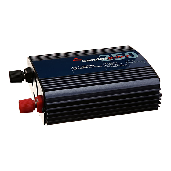
- Page 1 SAM Series owner's Please read this manual before Manual Power installing your Inverters inverter SAM-250-12 SAM-450-12 SAM-800-12...
-
Page 2: Table Des Matières
MANUAL | Index Section 1: Important Safety Instructions ..............1 Section 2: Description ................... 3 Features ..................... 3 Principle of Operation ................4 Section 3: Product Layout ..................6 Section 4: Installation ..................... 7 Section 5: Operation ................... 13 Section 6: Protections ................... -
Page 3: Important Safety Instructions
SECTION 1 | Safety important Safety inStructionS This manual contains important information regarding safety, operation, maintenance and storage of this product. before use, read and understand all cautions, warnings, in- structions and product labels, plus your vehicle’s battery manufacturer’s guidelines. failure to do so could result in injury and / or property damage. - Page 4 SECTION 1 | Safety caution! 1. The metal chassis of the inverter and the Grounding Terminal of the NeMA5-15r outlet(s) are internally bonded (connected) to the Negative DC Input Terminal on the inverter. In a vehicle / boat, the Negative Terminal of the battery is bonded to vehicle chassis / boat’s hull.
-
Page 5: Description
SECTION 2 | Introduction Description The inverter converts 12 VDC voltage from battery or from other suitable 12 VDC source to 115 V, 60 Hz AC voltage. The waveform of the of the AC output voltage is Modified Sine Wave. features • High peak efficiency of 90% • Very high power to weight ratio - compact and light weight • Soft Start Technology for better surge performance • Latest high power USB Charging Port, USB 3.0, Type A: 5 VDC, 2.1A • Load controlled cooling fan for better efficiency • Cool Surface Technology for cooler and safer touch temperature • Universal Protection circuit for low / high DC input voltage, overload / short circuit, over temperature and Ground fault • Low Interference Technology for controlled RF noise • Detachable DC input cables with 12V Power Plug (Cigar Plug) - not for SAM-800-12 model / battery Clamps... -
Page 6: Principle Of Operation
SECTION 2 | Introduction Load controlled cooling fan Cooling is carried out by convection and by forced air circulation by load-controlled fan. The fan will normally be off and will be switched oN automatically at the following loads: • SAM-250-12 and SAM-450-12: At load of 8W to 12W • SAM-800-12: At load of 35W to 45W... - Page 7 SECTION 2 | Introduction The output waveform of the inverter is a Modified Sine Wave. In a Modified Sine Wave, the voltage waveform consists of rectangular pulses that approximate sine wave pulses of a Pure Sine Wave. The voltage rises and falls abruptly at a particular phase angle and sits at 0 Volts for some time before changing its polarity. In a Pure Sine Wave, the voltage rises and falls smoothly with respect to phase angle and the voltage changes its polarity instantly when it crosses 0 Volts.
- Page 8 SECTION 3 | Layout Fig. 3.1 – SAM-250-12 Inverter Fig. 3.2 – SAM-450-12 Inverter Fig 3.3 – SAM-800-12 Inverter LeGenD 1. oN/off Switch 8. (-) Negative DC Input Terminal (M4 Thumb Screw) 2. NeMA5-15r outlet 9. opening for fan ventilation 3.
-
Page 9: Installation Environment
SECTION 4 | Installation Safety of installation Please read safety instructions on pages 1-2 before commencing installation. installation environment For best operating results, the inverter should be placed on flat surface, such as the ground, car floor, or other solid surface. The power cord allows easy positioning of the inverter. The inverter should only be used in locations that meet the following criteria: Dry- Do not allow water and/or other liquids to come into contact with the power inverter. In all marine applications, do not install the inverter below or near the waterline and keep the inverter away from moisture or water. -
Page 10: Dc Side Connections
SECTION 4 | Installation Dc Side connections General information 1. The metal chassis of the inverter and the Grounding Terminal of the NeMA5-15r outlet(s) are internally bonded (connected) to the Negative DC Input Terminal on the inverter. In a vehicle / boat, the Negative Terminal of the battery is bonded to vehicle chassis / boat’s hull. - Page 11 SECTION 4 | Installation resistance of Positive and Negative cables = 2 times the distance between the inverter and the battery). Up to 5% voltage drop has been considered. effects of low voltage on common electrical loads are given below: Lighting circuits – incandescent and Quartz/Halogen: Loss in light output because the bulb not only receives less power, but the cooler filament drops from white-hot towards red-hot, emitting much less visible light.
- Page 12 SECTION 4 | Installation making Dc Side connections using Detachable cable with 12V power plug (cigarette plug) Table 4.1 above gives details of cable with 12V Power Plug (Cigarette Plug) that has been provided for making detachable, temporary connection to the vehicle battery through the 12V Power outlet (Cigarette receptacle).
-
Page 13: Installation
SECTION 4 | Installation The thickness of the cables is required to be determined appropriately. The recommended cable sizes are based on the following 2 considerations (thicker of the two cable sizes has been recommended): • Excessive heating may lead to risk of insulation melt down and fire. Size is based on the maximum current carrying capacity (Ampacity) for conductor temperatures of 105°C in free air at 30°C ambient. • Excessive voltage drop will alarm and then shut down the inverter prematurely due to low DC input voltage protection of the inverter (10.5V ± 0.3V). Size is based on 5% voltage drop from the battery to the inverter at 1.25 times the maximum continuous... - Page 14 SECTION 4 | Installation 2. The Line and Neutral Terminals of the NeMA5-15r AC outlets are isolated from its Grounding Terminal. Thus, the metal chassis of the AC loads and the metal chassis of the inverter will also be isolated from the Line and Neutral. The Grounding Terminal of the AC outlet is connected to the input section of the electronic Ground fault Pro- tection Circuit on the Power Circuit board.
-
Page 15: Operation
SECTION 5 | Operation connecting Loads, Switching on & Switching off connecting Loads 1. Make sure that single load or the combined load requirement of your equipment does not exceed the inverter's output rating. 2. Switch off the inverter. 3. Switch off the load. 4. Plug the cord(s) from the load(s) into the AC receptacle(s) of the inverter 5. -
Page 16: Protections Monitoring & Troubleshooting
SECTION 6 | Protections Monitoring & Troubleshooting note: please refer to table 6.1 for status of monitoring LeDs and Buzzer for various protections / operational conditions explained below. over temperature protection The unit is cooled by load-controlled fan. In case the fan fails or if the cooling is inad- equate due to higher ambient temperature or restricted airflow, the temperature inside the inverter will exceed the safe temperature threshold and the unit will automatically shut down. - Page 17 SECTION 6 | Protections Monitoring & Troubleshooting info it is normal for the alarm to sound while the unit is being connected to or discon- nected from the power source. this is not indicative of a problem. Ground fault protection - General Due to loss of insulation as a result of aging of insulating materials, accident or malfunc- tion, voltage source inside an electrical device can get connected to its metal chassis.
- Page 18 SECTION 6 | Protections Monitoring & Troubleshooting failure to Start Some Devices on Load Some high capacitance loads like Compact fluorescent Lamp (CfL) or Switched Mode Power Supply (SMPS) will shut down the inverter under overload condition if the inverter is switched oN with these loads in oN condition.
- Page 19 SECTION 6 | Protections Monitoring & Troubleshooting operating threshold/ Green yeLLoW Buzzer remedy/reset condition/ reason LeD (5, LeD (6, LeD (4, protection power) input fault) fault) No output due Output power Check starting surge rating to Over Load is > Continu- of load.
-
Page 20: Protections
SECTION 7 | Specifications INVERTER PARAMETER SAM-250-12 SAM-450-12 SAM-800-12 input BATTERy SySTEM VOLTAGE 12 VDC NOMINAL INPUT VOLTAGE 12.5 VDC INPUT VOLTAGE RANGE > 10.8 VDC to < 15.4 VDC INPUT CURRENT AT CONTINUOUS POWER 22.3A to 24.2A 41.3A to 43.3A 72A to 75A INPUT CURRENT AT NO LOAD 0.2A to 0.3A... - Page 21 SECTION 7 | Specifications INVERTER PARAMETER SAM-250-12 SAM-450-12 SAM-800-12 Dc input caBLeS incLuDeD AWG#16 CABLE WITH 12V POWER PLUG (12V POWER PLUG CONTAINS REPLACEABLE 250V, 8A FUSE - BUSSMANN TyPE AGC-8) AWG#14 CABLE WITH BATTERy CLAMPS AWG#12 CABLE WITH BATTERy CLAMPS AWG#8 CABLE WITH BATTERy CLAMPS compLiance Conforms to UL STD 458...
-
Page 22: Warranty
SECTION 8 | Warranty 2 year LimiteD Warranty SAM-250-12, SAM-450-12 & SAM-800-12 manufactured by Samlex America, Inc. (the “War- rantor“) is warranted to be free from defects in workmanship and materials under normal use and service. The warranty period is 2 years for the United States and Canada, and is in effect from the date of purchase by the user (the “Purchaser“). - Page 23 Notes SAMLEX AMERICA INC. | 21...
- Page 24 Contact Information Toll Free Numbers Ph: 800 561 5885 Fax: 888 814 5210 Local Numbers Ph: 604 525 3836 Fax: 604 525 5221 Website www.samlexamerica.com USA Shipping Warehouse Kent WA Canadian Shipping Warehouse Delta BC Email purchase orders to orders@samlexamerica.com 11002-SAM-250-450-800-0114...
-
Page 25: Onduleur De Puissance De La Série Sam
Onduleur de Guide Veuillez lire ce guide AVANT d’Utilisation Puissance de d’installer votre la Série SAM onduleur. SAM-250-12 SAM-450-12 SAM-800-12... - Page 26 GUIDE | Index Section 1: Sécurité ..................... 1 Section 2: Description ................... 3 Caractéristiques..................3 Principes de Fonctionnement ..............4 Section 3: Disposition du Produit ................6 Section 4: Installation ..................... 7 Section 5: Fonctionnement ................... 13 Section 6: Protections ................... 14 Surveillance et Dépannage ..............
-
Page 27: Sécurité
SECTION 1 | Sécurité conSigneS de Sécurité importanteS Ce guide contient de l’information importante concernant la sécurité, le fonctionnement, l’entretien et le stockage du produit. Veuillez lire entièrement le guide et assurez-vous que vous comprenez tous les mises en garde, instructions et les étiquettes du produit et en plus, les consignes du fabricant à... - Page 28 SECTION 1 | Sécurité 4. Ne faites pas des connexions/déconnexions électriques dans les ports nécessitant une protection igniFuge, y compris des connexions d'Allume-Cigare de 12 VCC et des connexions de bornes. 5. L'onduleur n'est pas un jouet - Gardez le hors de portée des enfants. 6.
-
Page 29: Description
SECTION 2 | Introduction description Cet onduleur sert à convertir la tension de 12 VCC d’une batterie ou d’une autre source de tension appropriée à une tension de 115 VCA, 60 Hz. La forme d’onde de la tension de sortie CA est une Onde Sinusoïdale Modifiée. charactéristiques •... -
Page 30: Ventilateur Contrôlé Par La Charge
SECTION 2 | Introduction Ventilateur contrôlé par la charge Le refroidissement se passe par la convection et par la circulation d'air forcée grâce au ventilateur contrôlé par la charge. Le ventilateur serait normalement FERMÉ mais se met EN MARCHE automatiquement aux charges suivantes : •... - Page 31 SECTION 2 | Introduction La forme d'onde de sortie CA de l’onduleur est appelée l’Onde Sinusoïdale Modifiée. Elle a des pulsations rectangulaires qui ressemble (approximativement) aux pulsations de l’Onde Sinusoïdale Pure. La tension monte ou descende soudainement à une phase particulière et reste à...
- Page 32 SECTION 3 | Disposition La Fig. 3.1 – Onduleur SAM-250-12 La Fig. 3.2 – Onduleur SAM-450-12 La Fig 3.3 – Onduleur SAM-800-12 Légende 1. Interrupteur ON/OFF 9. Ouverture pour a Ventilation 2. Prise NEMA5-15R 10. Câble de batterie avec Allume-Cigare de 12V 3.
-
Page 33: Sécurité D'installation
SECTION 4 | Installation Sécurité d'installation Veuillez lire les consignes de sécurité aux pages 1 et 2 avant de faire l'installation. environnement d'installation Pour la meilleure performance, l'onduleur devrait etre mis sur une surface plate, comme la terre, le plancher d'une voiture, ou autre surface plate. Le fiche d'alimentation permet un emplacement facile de l'onduleur. -
Page 34: Information Générale
SECTION 4 | Installation sections de forte tensions internes. S'il est monté comme á la Fig 4.1(c), des matériaux chauds/ fondus des composants endommagés internes de l'unité (à cause d'un disfonctionnement) pourraient tomber sur des matérielles combustibles qui sont par terre, engendrant un risque d'incendie. -
Page 35: L'exigence D'un Fusible Dans La Connexion De Batterie
SECTION 4 | Installation spécifications, tailles, connexions et le chargement/déchargement des Batteries au Plomb- Acide, veuillez lire le document de présentation technique sur internet intitulé “Batteries, chargers and alternators” à www.samlexamerica.com sous Support/White papers. Bornes d'entrée cc. Des bornes d'Entrées CC fabriquées sur mesure en utilisant un arrangement d'écrou / de vis à... - Page 36 SECTION 4 | Installation Table montre aussi les classifications de fusibles externes (pas inclus) à utiliser quand vous utilisez des câbles avec une pince de batterie. Les câbles terminent avec des cosses personalisées de12,5 mm x 8,5 mm pour la connexion à...
-
Page 37: Installation
SECTION 4 | Installation Faire des connexions du côté cc en utilisant un câble avec des pinces de Batterie La table 4.1 au-dessus montre les détails des câbles d'entrée CC avec des pinces de batterie qui ont été fournis pour faire une connexion temporaire à la batterie de 12V. attention! • Veuillez assurer que le fusible externe recommandé spécifique dans la Table 4.1 au-dessus (fusible pas inclus) est installé... -
Page 38: Information Général
SECTION 4 | Installation Comme expliqué au-dessus les câbles de batterie de 90 cm terminent avec des cosses per- sonalisées de12,5 mm x 8,5 mm à pour la connexion à l'onduleur composées d'un arrange- ment d'écrou et de vis à serrage à main M4 (7, 8 dans la Fig 3.1 à 3.3). Pour la connexion à l'onduleur avec des câbles plus longs/épais, utilisez les cosses personalisées avec un trou de 4,5 mm fournies avec un ensemble de pinces de batterie. -
Page 39: Fonctionnement
SECTION 5 | Fonctionnement connexion des charges, allumage & mise à arrêt connexion de la charge 1. Assurez que l'exigence de charge ou de charges combinées de l'équipement n'excède pas la sortie nominale de l'onduleur. 2. Fermez l'onduleur. 3. Fermez la charge. 4. -
Page 40: Surveillance Et Dépannage
SECTION 6 | Protections, Surveillance & Dépannage avis: Veuillez réferer à la table 6.1 pour le statut des deLs de surveillance et de l'alarme pour des les divers protections / conditions de fonctionnement expliqués ci-dessous. protection de Surchauffe L'unité est refroidie par un ventilateur contrôlé par la charge. S'il y a un échec du ventilateur ou si le refroidissement n'est pas suffisant à... - Page 41 SECTION 6 | Protections, Surveillance & Dépannage info c'est normale si l'alarme sonne quand l'unité est branchée / débranchée de la source de puissance. Ça n'indique pas un problème. protection de défaut à terre - générale À cause d'un manque de l'isolation grâce à la vieillissement des matériaux, d'un accident ou d'un disfonctionnement, la source de tension dans le dispositif électrique peut être connecter au châssis métallique.
- Page 42 SECTION 6 | Protections, Surveillance & Dépannage échec d'allumage pour quelques dispositifs sur charge Quelques charges fortement capacitives comme une Lampe Fluorescente Compacte (LFC) ou un Alimentation à Découpage vont causer une condition de surcharge si l'onduleur est allumé quand les charges sont déjà allumées. Mais, si les charges sont fermeés en premier et puis rallumez 10 secondes après que l'onduleur soit allumé, l'onduleur ne va pas forcé- ment se fermer.
- Page 43 SECTION 6 | Protections, Surveillance & Dépannage Verte Jaune condition rouge de Service/ plage/ alarme remède/ puis- défaut de protection raison Sonore réinitialisation sance) l'entrée) défaut) Pas de Sortie Puissance MARCHE ARRÊT MARCHE ARRÊT Vérifiez la surtension nominale à cause d'une de Sortie >...
-
Page 44: Spécifications
SECTION 7 | Spécifications PARAMÈTRES D'ONDULEUR SAM-250-12 SAM-450-12 SAM-800-12 entrée TENSION DE SySTèME DE BATTERIE 12 VCC TENSION D'ENTRéE NOMINALE 12,5 VCC PLAGE DE TENSION D'ENTRéE > 10,8 VCC á < 15,4 VCC COuRANT D'ENTRéE à PuISSANCE CONTINuE 22,3A á 24,2A 41,3A á... - Page 45 SECTION 7 | Spécifications PARAMÈTRES D'ONDULEUR SAM-250-12 SAM-450-12 SAM-800-12 cÂBLe d'éntrée cc compriS CÂBLE de AWG #16 AVEC CORDON D'ALIMENTATION DE 12V (QuI CONTIEN uN FuSIBLE REMPLACEABLE DE250V, 8A - TyPE BuSSMANN, AGC-8) CÂBLE AVEC PINCES DE BATTERIE, AWG #14 CÂBLE AVEC PINCES DE BATTERIE, AWG #12 CÂBLE AVEC PINCES DE BATTERIE, AWG #8 conFormité...
-
Page 46: Garantie
SECTION 8 | Garantie garantie Limitée de 2 anS SAM-250-12, SAM-450-12 et SAM-800-12, fabriqués par Samlex America, Inc. (le « Ga- rant ») sont garantis être non défectueux dans la conception et dans les matériaux, moyennant une utilisation et un service normaux. La période de garantie est de 2 ans pour les Etats-Unis et le Canada, et prend effet le jour de l’achat par l’utilisateur («... - Page 47 SECTION 8 | Garantie revenus ou de bénéfices, ou autres dommages collatéraux, pouvant être rapportés comme ayant survenus au cours de l’utilisation ou de la vente du matériel, y compris tous disfonctionnements ou échecs du matériel, ou une partie de celui-ci. Le Garant n’assume aucune responsabilité...
- Page 48 Contact Information Toll Free Numbers Ph: 800 561 5885 Fax: 888 814 5210 Local Numbers Ph: 604 525 3836 Fax: 604 525 5221 Website www.samlexamerica.com USA Shipping Warehouse Kent WA Canadian Shipping Warehouse Delta BC Email purchase orders to orders@samlexamerica.com 11002-SAM-250-450-800-0114 FR...