Table des Matières
Publicité
Les langues disponibles
Les langues disponibles
Liens rapides
Installation Manual
SAFETY PRECAUTIONS
•
Read the following "SAFETY PRECAUTIONS" carefully before installation of Domestic Hot Water Tank Unit (hereafter referred to as "Tank Unit").
•
Electrical works and water installation works must be done by licensed electrician and licensed water system installer respectively. Be sure to use the
correct rating and main circuit for the model to be installed.
•
The caution items stated here must be followed because these important contents are related to safety. The meaning of each indication used is as below.
Incorrect installation due to ignorance or negligence of the instructions will cause harm or damage, and the seriousness is classifi ed by the following
indications.
WARNING
This indication shows the possibility of causing death or serious injury.
CAUTION
This indication shows the possibility of causing injury or damage to properties only.
The items to be followed are classifi ed by the symbols:
Symbol with white background denotes item that is PROHIBITED from doing.
Symbol with dark background denotes item that must be carried out.
•
Carry out test run to confi rm that no abnormality occurs after the installation. Then, explain to user the operation, care and maintenance as stated in
instructions. Please remind the customer to keep the operating instructions for future reference.
•
If there is any doubt about the installation procedure or operation, always contact the authorized dealer for advice and information.
Do not use unspecifi ed cord, modifi ed cord, joint cord or extension cord for power supply cord. Do not share the single outlet with other electrical
appliances. Poor contact, poor insulation or over current will cause electrical shock or fi re.
Do not tie up the power supply cord into a bundle by band. Abnormal temperature rise on power supply cord may happen.
Keep plastic bag (packaging material) away from small children, it may cling to nose and mouth and prevent breathing.
Do not purchase unauthorized electrical parts for installation, service, maintenance and etc.. They might cause electrical shock or fi re.
Do not modify the wiring of Tank Unit for installation of other components (i.e. heater, etc). Overloaded wiring or wire connection points may cause
electrical shock or fi re.
For electrical work, follow local wiring standard, regulation and this installation instruction. An independent circuit and single outlet must be used.
If electrical circuit capacity is not enough or defect found in electrical work, it will cause electrical shock or fi re.
For water circuit installation work, follow to relevant European and national regulations (including EN61770) and local plumbing and building
regulation codes.
Engage dealer or specialist for installation. If installation done by the user is defective, it will cause water leakage, electrical shock or fi re.
Install according to this installation instructions strictly. If installation is defective, it will cause water leakage, electrical shock or fi re.
Install at a strong and fi rm location which is able to withstand the set's weight. If the strength is not enough or installation is not properly done, the
set will drop and cause injury.
This equipment is strongly recommended to be installed with Residual Current Device (RCD) on-site according to the respective national wiring
rules or country-specifi c safety measures in terms of residual current.
Only use the supplied or specifi ed installation parts, else, it may cause unit vibrate loose, water leakage, electrical shock or fi re.
The unit is only for use in a closed water system. Utilization in an open water circuit may lead to excessive corrosion of water piping and risk of
incubating bacteria colonies, particularly Legionella, in water.
If there is any doubt about the installation procedure or operation, always contact the authorized dealer for advice and information.
Select a location where in case of water leakage, the leakage will not cause damage to other properties.
When installing electrical equipment at wooden building of metal lath or wire lath, in accordance with electrical facility standard, no electrical contact
between equipment and building is allowed. Insulator must be installed in between.
Any work carried out on the Tank Unit after removing the front panel which is secured by screws, must be carried out under the supervision of
authorized dealer and licensed installation contractor.
For cold water supply has a backfl ow regulator, check valve or water meter with check valve, provisions for thermal expansion of water in the hot
water system must be provided. Otherwise it will cause water leakage.
The piping installation work must be fl ushed before Tank Unit is connected to remove contaminants. Contaminants may damage the Tank Unit
components.
The installation may be subjected to building regulation approval applicable to respective country that may require to notify the local authority
before installation.
The Tank Unit must be shipped and stored in upright condition and dry environment. It may laid on its back when being moved into the building.
This unit must be properly earthed. The electrical earth must not be connected to a gas pipe, water pipe, the earth of lightening rod or a telephone.
Otherwise there is a danger of electrical shock in the event of an insulation breakdown or electrical earth fault in the Tank Unit.
WARNING
EN ......................1
ES ......................5
IT .......................9
NL ....................13
PT ....................17
GR ...................21
BG ...................25
FR ....................29
DE ....................33
1
Publicité
Table des Matières

Manuels Connexes pour Panasonic WH-TD20E3E5


Sommaire des Matières pour Panasonic WH-TD20E3E5
- Page 1 EN ......1 ES ......5 IT .......9 NL ....13 PT ....17 GR ....21 Installation Manual BG ....25 FR ....29 SAFETY PRECAUTIONS DE ....33 • Read the following “SAFETY PRECAUTIONS” carefully before installation of Domestic Hot Water Tank Unit (hereafter referred to as “Tank Unit”). •...
-
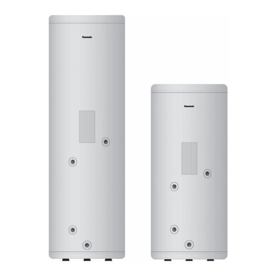
Page 2: Main Components
It may need three or more people to carry out the installation work. The weight of Tank Unit might cause injury if carried by two person. MAIN COMPONENTS Dimension (mm) Capacity Model (Litre) Height Diameter WH-TD20E3E5 1150 WH-TD30E3E5-1 1600 Main components 1 Hot water outlet – 19.05 mm (3/4"BSP) 2 Electrical box 3 Sensor socket – 12.70 mm (1/2"BSP) Reset button 4 Flow inlet –... - Page 3 Valve Cable Cord Thermostat Cable Cable Cable PIPING AND WIRING INSTALLATION Obstacle 2 Anode bar insert Hot water connection Panasonic Heating B side A side 4 3-way valve 3 Safety valve Drain connection water discharge (3/4"BSP) Connection (1/2"BSP) Water supply valve (fi...
- Page 4 WARNING This section is for authorized and licensed electrician / water system installer only. Be sure to switch off all power supply (Tank Unit power supply, indoor unit power supply, heater power supply etc.) before performing installation. 1. Install adjustable legs at bottom of tank (3 locations) then adjust the height until the unit stable. 2.
-
Page 5: Medidas De Seguridad
EN ......1 ES ......5 IT .......9 NL ....13 PT ....17 GR ....21 Manual de instalación BG ....25 FR ....29 DE ....33 MEDIDAS DE SEGURIDAD • Lea cuidadosamente las siguientes “MEDIDAS DE SEGURIDAD” antes de la instalación del Acumulador ACS de depósito de agua caliente doméstica (de ahora en adelante referido como “Acumulador ACS”). -
Page 6: Componentes Principales
COMPONENTES PRINCIPALES Dimensión (mm) Capacidad Modelo (Litros) Altura Diámetro WH-TD20E3E5 1150 WH-TD30E3E5-1 1600 Componentes principales 1 Retorno agua caliente – 19,05 mm (3/4"BSP) 2 Caja eléctrica Botón de reinicio 3 Toma del sensor – 12,70 mm (1/2"BSP) Corte de seguridad 4 Entrada de fl... - Page 7 INSTALACIÓN DE TUBERÍA Y CABLEADO Obstáculo 2 Inserción de barra ánodo Conexión de agua caliente Panasonic Calefacción lado A lado B 4 Válvula de 3 vías 3 Válvula de seguridad Conexión de drenaje de descarga de agua (3/4"BSP) Conexión (1/2"BSP)
-
Page 8: Carga Del Agua
ADVERTENCIA Esta sección está destinada únicamente a electricistas / instaladores de sistemas de agua autorizados y capacitados. Asegúrese de desconectar todas las fuentes de alimentación de corriente (alimentación de corriente de unidad de acumulador ACS, alimentación de corriente de unidad interna, alimentación de corriente de resistencia eléctrica de refuerzo, etc.) antes de realizar la instalación. 1. -
Page 9: Manuale D'installazione
EN ......1 ES ......5 IT .......9 NL ....13 PT ....17 GR ....21 Manuale d’installazione BG ....25 FR ....29 DE ....33 MISURE DI SICUREZZA • Leggere attentamente le seguenti “MISURE DI SICUREZZA” prima di procedere all’installazione del Bollitore dell’Acqua Calda ad Uso Domestico (di seguito defi... -
Page 10: Componenti Principali
– 12,70 mm (1/2"BSP) collega il Bollitore all’Unità 8 Connettoreanodico – 19,05 mm (3/4"BSP) interna della pompa Parti accessorie di calore Aria-Acqua Panasonic (eccetto che per A. Valvola a 3 vie i modelli S*H) B. Sensore C. Manuale d’installazione Elemento elettrico D. - Page 11 INSTALLAZIONE DEI TUBI E DELL’IMPIANTO ELETTRICO Ostacolo 2 Inserimento barra anodica Collegamento dell’acqua calda Panasonic Riscaldamento Lato B Lato A 4 Valvola a 3 vie 3 Valvola di sicurezza Scarico dell’acqua con collegamento di scolo (3/4"BSP) Collegamento (1/2"BSP)
-
Page 12: Caricamento Dell'acqua
AVVERTENZA Questa sezione è riservata solamente agli elettricisti / installatori del sistema idrico autorizzati e qualifi cati. Accertarsi di spegnere l’alimentazione elettrica (alimentazione elettrica del Bollitore, alimentazione elettrica dell’unità interna, alimentazione elettrica del riscaldatore ecc.) prima di procedere all’installazione. 1. Installare le gambe regolabili alla base de serbatoio (3 punti), quindi regolare l’altezza fi no a quando l’unità non risulta stabile. 2. - Page 13 EN ......1 ES ......5 IT .......9 NL ....13 PT ....17 GR ....21 Installatiehandleiding BG ....25 FR ....29 DE ....33 VEILIGHEIDSMAATREGELEN • Lees met aandacht de volgende "VEILIGHEIDSMAATREGELEN" voordat u de huishoudelijke heet watertankunit (hierna genoemd de "tankunit") installeert. • Werk dat te maken heeft met electriciteit en met de installatie van waterinstallaties moet uitgevoerd worden door gediplomeerde elektriciens respectievelijk gediplomeerde installateurs van watersystemen.
- Page 14 Het kan zijn dat er drie of meer personen nodig zijn voor het uitvoeren van de installatiewerkzaamheden. Lemand die alleen de tankunit draagt, zou zich kunnen vertillen. HOOFDCOMPONENTEN Capaciteit Afmeting (mm) Model (Liter) Hoogte Diameter WH-TD20E3E5 1150 WH-TD30E3E5-1 1600 Hoofdcomponenten 1 Warmwateruitgang – 19,05 mm (3/4"BSP) 2 Elektrische doos Reset-knop 3 Sensorsok – 12,70 mm (1/2"BSP) Onderbreker voor 4 Toevoer heet water –...
- Page 15 OLP- regelaar WH-S*F / WH-M*F) klepkabel klepkabel boosterverwarming Kamerthermostaat kabel INSTALLATIE LEIDINGEN EN BEKABELING Obstakel 2 Insteken anodebalk Aansluiting voor heet water Panasonic Verwarmen A-kant B-kant 4 Driewegklep 3 Veiligheidsklep Wateruitlaat afvoeraansluiting (3/4"BSP) Aansluiting(1/2"BSP) Watertoevoerklep (ter plaatse te leveren) T-verbindingsstuk...
- Page 16 WAARSCHUWING Deze sectie is alleen voor gemachtigde en gelicentieerde elektriciens en installateurs van watersystemen. Zorg ervoor alle stroomvoorzieningen uit te schakelen (voeding tankunit, voeding binnenunit en voeding verwarming, enz) voordat u de installatie uitvoert. 1. Installeer aanpasbare poten aan onderkant van tank (3 locaties) en pas vervolgens de hoogte aan, totdat de eenheid stabiel is. 2.
-
Page 17: Manual De Instalação
EN ......1 ES ......5 IT .......9 NL ....13 PT ....17 GR ....21 Manual de Instalação BG ....25 FR ....29 DE ....33 PRECAUÇÕES DE SEGURANÇA • Leia as seguintes “PRECAUÇÕES DE SEGURANÇA” cuidadosamente antes de instalar o Depósito de Água Quente Doméstico (doravante designado por “Depósito”). •... -
Page 18: Componentes Principais
Poderão ser necessárias duas ou mais pessoas para executar a instalação. O peso do Depósito pode causar danos se transportado por uma só pessoa. COMPONENTES PRINCIPAIS Capacidade Dimensões (mm) Modelo (Litros) Altura Diâmetro WH-TD20E3E5 1150 WH-TD30E3E5-1 1600 Componentes principais 1 Saída de água quente – 19,05 mm (3/4"BSP) 2 Caixa eléctrica Botão de 3 Suporte do sensor – 12,70 mm (1/2"BSP) reinicialização... - Page 19 Booster Ambiente (OLP) INSTALAÇÃO DA TUBAGEM E CABLAGEM Obstáculo 2 Encaixe da barra de ânodo Ligação da água quente Panasonic Aquecimento Lado B Lado A 4 Válvula de 3 vias 3 Válvula de segurança Ligação de drenagem para descarga de água (3/4"BSP) Ligação (1/2"BSP)
-
Page 20: Examine O Ânodo Anualmente
ADVERTÊNCIA Esta secção destina-se apenas a electricistas licenciados / instaladores de sistemas de água licenciados. Antes de efectuar a instalação, certifi que-se de que toda a corrente eléctrica (Fonte de alimentação do Depósito, fonte de alimentação da unidade interior, fonte de alimentação do aquecedor, etc.) foi desligada. 1. -
Page 21: Προφυλαξεισ Ασφαλειασ
EN ......1 ES ......5 IT .......9 NL ....13 PT ....17 GR ....21 Εγχειρίδιο εγκατάστασης BG ....25 FR ....29 DE ....33 ΠΡΟΦΥΛΑΞΕΙΣ ΑΣΦΑΛΕΙΑΣ • Διαβάστε τις ακόλουθες "ΠΡΟΦΥΛΑΞΕΙΣ ΑΣΦΑΛΕΙΑΣ" προσεκτικά πριν την εγκατάσταση της Οικιακής Μονάδας Δεξαμενής Ζεστού Νερού (η όποια εφεξής θα αναφέρεται... - Page 22 συνδέετε τη Μονάδα 8 Συνδετήρας ανόδου – 19,05 mm (3/4"BSP) δεξαμενής σε Εσωτερική μονάδα αντλίας Εξαρτήματα θερμότητας αέρος-νερού A. Τρίοδος βαλβίδα Panasonic (εκτός από το B. Αισθητήρας μοντέλο S*H) C. Εγχειρίδιο εγκατάστασης Ηλεκτρικό στοιχείο D. Βαλβίδα ασφαλείας 5/4"BSP E. Ρυθμιζόμενα πόδια x 3 Διάμετρος...
- Page 23 WH-S*F / WH-M*F) βαλβίδας δεξαμενής ελεγκτή βαλβίδας δωματίου ΣΩΛΗΝΩΣΕΙΣ ΚΑΙ ΚΑΛΩΔΙΩΣΗ ΕΓΚΑΤΑΣΤΑΣΗΣ Εμπόδιο 2 Είσοδος Ανοδικής μπάρας Σύνδεση ζεστού νερού Panasonic Θέρμανση Πλευρά A Πλευρά Β 4 Τρίοδος βαλβίδα 3 Βαλβίδα ασφαλείας Σύνδεση αποστράγγισης αποχέτευσης νερού (3/4"BSP) Σύνδεση (1/2"BSP) Βαλβίδα παροχής...
- Page 24 ΠΡΟΕΙΔΟΠΟΙΗΣΗ Το κεφάλαιο αυτό αφορά εξουσιοδοτημένους και αδειούχους ηλεκτρολόγους / υδραυλικούς μόνο. Σιγουρευτείτε ότι κλείσατε κάθε παροχή ρεύματος (παροχή ρεύματος Μονάδας δεξαμενής, παροχή ρεύματος εσωτερικής μονάδας, παροχή ρεύματος θερμαντήρα κλπ.) πριν κάνετε την εγκατάσταση. 1. Εγκαταστήστε ρυθμιζόμενα πόδια στο κάτω μέρος της δεξαμενής (3 σημεία) και έπειτα ρυθμίστε το ύψος μέχρι η μονάδα να σταθεροποιηθεί. 2.
-
Page 25: Ръководство За Монтаж
EN ......1 ES ......5 IT .......9 NL ....13 PT ....17 GR ....21 Ръководство за монтаж BG ....25 FR ....29 DE ....33 ПРЕДПАЗНИ МЕРКИ • Прочетете внимателно “ПРЕДПАЗНИ МЕРКИ” по-долу, преди да инсталирате Домашния резервоар за топла вода (наричан по-нататък “Резервоар”). - Page 26 проводник, когато станция – 12,70 мм (1/2"BSP) свързвате резервоара 8 Аноден конектор – 19,05 мм (3/4"BSP) към вътрешно тяло - Допълнителни части термопомпа на Panasonic (с изключение на модел S*H) A. 3-пътен клапан B. Сензор C. Ръководство за монтаж Електрически...
- Page 27 вентил нагревател термостат вентил на резервоара МОНТАЖ НА ТРЪБИТЕ И ЕЛЕКТРИЧЕСКА ИНСТАЛАЦИЯ Препятствие 2 Гнездо за анодния прът Връзка за гореща вода Panasonic Отопление Страна В Страна А 4 3-пътен клапан 3 Предпазен клапан Дренажна връзка изхвърляне на водата (3/4"BSP) Връзка...
-
Page 28: Предпазни Мерки При Употреба
ПРЕДУПРЕЖДЕНИЕ Тази част е само за оторизирани и лицензирани електротехници / инсталатори на водни системи. Уверете се, че всичкото електрозахранване е изключено (електрозахранването на резервоара, електрозахранването на вътрешното тяло, електрозахранването на нагревателя и т.н.), преди извършване на монтажа. 1. Монтирайте регулиращите се крака в долната част на резервоара (3 места), след което регулирайте височината, така че уредът да е стабилен. -
Page 29: Précautions D'installation
EN ......1 ES ......5 IT .......9 NL ....13 PT ....17 GR ....21 Manuel d’installation BG ....25 FR ....29 DE ....33 PRÉCAUTIONS D’INSTALLATION • Veuillez lire attentivement les « PRÉCAUTIONS DE SÉCURITÉ » avant d’installer le réservoir d’eau chaude domestique (ci-dessous désigné « Réservoir »). •... -
Page 30: Composants Principaux
7 Doigt de gant sonde station solaire – 12,70 mm (1/2"BSP) réservoir à une unité 8 Connecteur d’anode – 19,05 mm (3/4"BSP) intérieure de pompe à chaleur air-eau Pièces accessoires Panasonic (à l’exception du modèle S*H) A. Vanne 3 voies B. Sonde ECS Résistance d’ appoint C. Manuel d’installation 5/4"BSP... -
Page 31: Installation Des Conduites Et Des Câbles
INSTALLATION DES CONDUITES ET DES CÂBLES Obstacle 2 Insert de la barre porte-anode Sortie eau chaude Panasonic Chauffage Côté B Côté A 4 Vanne 3 voies ECS 3 Soupape de sécurité ( non fournie ) Vidange à raccorder à l’égout (3/4"BSP) -
Page 32: Remplissage
AVERTISSEMENT La présente section s’adresse à un électricien et à un plombier agréés. Assurez-vous de couper l’alimentation électrique (alimentation électrique du réservoir, alimentation électrique de l’unité intérieure, alimentation du dispositif de chauffage, etc.) avant de procéder à l’installation. 1. Installez les pieds réglables à la base du ballon (à 3 endroits), puis réglez la hauteur jusqu’à ce que clui-ci soit stable. 2. -
Page 33: Sicherheitshinweise
EN ......1 ES ......5 IT .......9 NL ....13 PT ....17 GR ....21 Installationsanleitung BG ....25 FR ....29 DE ....33 SICHERHEITSHINWEISE • Bitte lesen Sie die folgenden „SICHERHEITSHINWEISE“ vor der Installation des Warmwasserspeichergeräts (hierin im Folgenden „Warmwasserspeicher“ genannt) sorgfältig durch. • Elektro- und Wasseranschlussarbeiten müssen von einem ausgebildeten Elektriker bzw. - Page 34 Verletzungen führen, falls er nur von zwei Personen getragen wird. HAUPTBESTANDTEILE Abmessungen (mm) Fassungs- Modell vermögen (l) Höhe Durchmesser WH-TD20E3E5 1150 WH-TD30E3E5-1 1600 Hauptbestandteile 1 Warmwasseraustritt – 19,05 mm (3/4 " BSP) 2 Anschlusskasten 3 Fühler-Tauchhülse – 12,70 mm (1/2 " BSP)
- Page 35 WH-S*F / WH-M*F zu) Wege-Ventil Wege-Ventil Speicher E-Heizstab Raumthermostat fühler-Kabel Speichers ANSCHLUSS VON ROHRLEITUNGEN UND ELEKTRISCHEN LEITUNGEN Hindernis 2 Schutzanode Warmwasseraustritt Panasonic Heizung Seite B Seite A 4 3-Wege-Ventil 3 Sicherheitsventil Entleerungsanschluss (3/4 " BSP) Anschluss (1/2 " BSP) Frischwasserventil| (bauseits) T-Stück...
-
Page 36: Entleeren Des Speichers
WARNUNG Dieser Abschnitt richtet sich ausschließlich an autorisierte und qualifi zierte Elektriker bzw. Wasserinstallateure. Stellen Sie vor der Montage auf jeden Fall alle Stromversorgungen (des Warmwasserspeichers, des Innengeräts, der Heizung usw.) ab. 1. Am Boden des Speichers sind 3 die drei mitgelieferten verstellbaren Standfüße anzubringen, die so einzustellen sind, dass der Speicher stabil steht. 2.