Daikin FWTOUCH Manuel D'installation Et D'utilisation
Table des Matières
Les langues disponibles
Les langues disponibles
Liens rapides
FWTOUCH
Installation and use manual
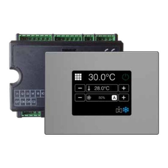
Touch screen display interface
Manuale di installazione e uso
Interfaccia utente touch screen
Manuel d'installation et d'utilisation
Interface utilisateur touch screen
Installations- und Bedienungsanleitung
Touchscreen-Bedienoberfläche
Manual de instalación y uso
Interfaz del usuario con pantalla táctil
EN
IT
FR
DE
ES
Chapitres
Table des Matières
Dépannage

Sommaire des Matières pour Daikin FWTOUCH
- Page 58 TABLE DES MATIÈRES RECOMMANDATIONS GÉNÉRALES � � � � � � � � � � � p� 59 6�6�1 Activation� � � � � � � � � � � � � � � � � � � � � � � � � � � � � � � � � � � � � � � � � � p� 71 DÉSHUMIDIFICATION �...
-
Page 59: Recommandations Générales
Ce manuel peut subir des modifications à tout moment et sans préavis, aux fins de amélioration le produit. Daikin décline toute responsabilité dans les cas suivants: l’appareil a été installé par des techniciens non qua- lifiés; il a été utilisé de manière impropre ou dans des conditions non admises; il n'a pas été soumis aux opé- rations d'entretien figurant dans le présent manuel;... -
Page 60: Fonctions Principales
FWTOUCH à différents ni- 2. MASTER de zone (FWTOUCH), réception d’instruc- veaux d’autonomie: tions de MASTER de réseau RS485, envoi d’instruc- 1. MASTER de réseau RS485 (Supervision ou tions aux SLAVE OC; FWTOUCH), envoi d’instructions aux SLAVE RS485 3. -
Page 61: Pages Et Fonctions
PAGES ET FONCTIONS INTERFACE UTILISATEUR Modalité Été (rafraîchissement) Modalité Hiver (chauffage) 4.1.1 Accès au menu utilisateur L'accès au menu utilisateur est autorisé uniquement dans le cas où le clavier n’aurait pas été bloqué ou dans le cas où la fonction de limitation utilisateur n’aurait pas été... -
Page 62: Menu Utilisateur
QUEMENT si les résistances électriques sont présentes. jour de la semaine (du lundi au dimanche). Ū Appuyer sur les touches COPY pour copier le profil Été et Hiver d’un jour de la semaine sur un ou plu- sieurs autres jours de la semaine. FWTOUCH... -
Page 63: Menu Entretien
MENU ENTRETIEN 4.3.1 Menu informations M I N Touche de retour à la page principale Touche de retour à la page principale Touche d’accès à la liste des paramètres de configuration (mot de passe = 10)voir paragraphe p. 64 Touche d’accès à la page des versions logiciels Touche d’accès à... -
Page 64: Liste Paramètres
La carte de puissance présente une sortie numérique Toujours ON, C17 Modalité ventilation Standard Toujours OFF, (indiquée par O7 sur le schéma électrique) dont l’état en STAND-BY Allumages cycliques peut être lié à un des états de fonctionnement de l’unité hydronique indiqués dans la liste ci-après : FWTOUCH... -
Page 65: Modalité Stand-By
Ū Absence du signal d'eau au chauffage En cas d’interruption du branchement sériel avec la Ū Absence du signal d'eau au refroidissement commande réglée comme SLAVE, FWTOUCH main- Ū Par le superviseur et sélectionnables à l’aide du tient les réglages ON/OFF et modalité ÉTÉ/HIVER as- paramètre de configuration « Configuration O7 ». -
Page 66: Liste Paramètres De Réseau Et Connexions
Adresse sérielle (MASTER = 0; SLAVE = 1-255) 1200 2400 4800 Vitesse 9600 9600 19200 38400 Contrôle température par Master SETUP OC Master MST/SLV Master Slave FWTOUCH master:0 Adresse sérielle FWTOUCH Slave: 2-255 RÉGLAGE réseau sans fil Activation Wi-Fi/BLE (Bluetooth) FWTOUCH... -
Page 67: Logiques De Réglage
LOGIQUES DE RÉGLAGE COMMUTATION ÉTÉ/HIVER mode de fonctionnement Local est momentané- Quatre logiques différentes et alternatives de sélec- ment rétabli. tion du mode de fonctionnement du thermostat sont disponibles ; elles sont définies sur la base de la confi- Ū en fonction de la température de l'air : guration programmée sur la commande : Ū... -
Page 68: Ventilation Modulée
La logique de gestion de la ventilation modulée pré- FONCTIONNEMENT AUTOMATIQUE POUR UNITÉ HY- voit, tout comme la ventilation par paliers, deux mo- DRONIQUE À 3 VITESSES ET VANNE(S) MODULANTE(S) dalités de fonctionnement : 1. Vitesse MINIMUM Ū fonctionnement AUTOMATIQUE 2. Vitesse MOYENNE FWTOUCH... -
Page 69: Vitesse Forcée
Ū fonctionnement à VITESSE FIXE lecture plus précise de la température ambiante La sélection du pourcentage de fonctionnement s’ef- Ū si la ventilation en stand-by est toujours réglée sur fectue à l’aide des touches + et - ; alors qu’en réglant ON, la vitesse sélectionnée est maintenue une fois une valeur de ventilation inférieure au minimum la valeur de consigne de température atteinte. -
Page 70: Vanne
à l’aide du paramètre de configuration correspondant et son utilisation activée à l’aide de la touche du MENU UTILISATEUR, la résistance élec- trique est utilisée à la demande du thermostat en fonction de la température ambiante : INFO : L’activation prévoit un forçage de la FWTOUCH... -
Page 71: Validation Résistance Par Sonde À Eau
ventilation. Cette commande n’est pas fournie si la sonde à eau n’est pas prévue ou bien est débranchée. 6.4.2 Validation résistance par sonde à eau La commande d’activation de la résistance est liée au contrôle de la température de l’eau. Ci-après, la logique d’activation correspondante : CHAUFFAGE ECONOMY... -
Page 72: Validation Déshumidification Par Sonde À Eau
Ū Alarme non grave de ID (déclenchée par la ferme- ture de l’entrée ID4) Ū Alarme grave de ID (déclenchée par la fermeture de l’entrée ID5) Ū Alarme connexion OC (déclenchée par la perte de Water probe alarm connexion de l’écran avec la carte) FWTOUCH... -
Page 73: Réseaux Et Connectivité
Ū 1 bit stop Les fonctions reconnues et gérées par la commande Dans un réseau de supervision, chaque commande comme SLAVE sont les suivantes : FWTOUCH se comporte comme un SLAVE à l’égard du Code Description système de gestion centralisé qui constitue le MAS- lecture de coil status TER du réseau. - Page 74 1 = vit. super minimum Type vanne (ABSENTE/ON-OFF/MODULÉE) 2 = vit. minimum 3 = vit. moyenne 4 = vit. maximum Valeur % de la ventilation modulée Valeur % de la sortie analogique 1 Valeur % de la sortie analogique 2 FWTOUCH...
-
Page 75: Solutions De Réseau « Small
MASTER alors que les autres commandes autre réseau, pas même de supervision dans la me- FWTOUCH du réseau assurent la fonction de SLAVE. sure où les ports sériels RS485 de toutes les com- Deux types de réalisation existent, chacune avec des mandes (aussi bien MASTER que SLAVE) sont déjà... -
Page 76: Réseau Mixte
RS485 de la commande MASTER, en obtenant seau de supervision. » Tableau récapitulatif des paramètres SMALL RS485 Supervision BMS SMALL RS485 Réseau mixte FWTOUCH Master: Master - FWTOUCH Master: Master MST/SLV Slave de SPV FWTOUCH Slave FWTOUCH Slave SLAVE de PSV SLAVE de PSV... -
Page 77: Signification Des Voyants
SIGNIFICATION DES VOYANTS Bleu Vert Rouge État des voyants Unité hydronique OFF Unité hydronique ON Présence alarme Absence Voyant réseau Master OC Communication OK communication INFO : En faisant face à la carte de puissance, le voyant de réseau (NETWORK LED) est à gauche tandis que le voyant d’état (STATUS LED) est à... -
Page 78: Données Techniques
à Daikin. 10.1 INSTALLATION DES SONDES La commande FWTOUCH gère les sondes suivantes : l’eau : il est possible de connecter une ou deux Ū Sonde de lecture de la température d’air intégrée sondes selon que l’unité... -
Page 79: Installation De La Sonde D'air À Distance
10.2 INSTALLATION DE LA SONDE D’AIR À DISTANCE L’utilisation de la sonde d’air à distance pour le ré- La sonde d'air à distance est toujours branchée aux glage de la température ambiante est une option. bornes L1-IC de la carte de puissance. FWV/L/M-D &... -
Page 80: Installation De L'interface Utilisateur
électrique fourni avec quées dans le tableau des données électriques. l'unité hydronique installée et dans le respect des ATTENTION : Avant de procéder à une quelconque normes en vigueur. intervention sur des composants électriques, FWTOUCH... -
Page 81: Entretien
Pour nettoyer au besoin le panneau de contrôle (in- terface utilisateur) : 10.8 RÉSOLUTION DES PROBLÈMES Si l’unité à laquelle la commande FWTOUCH est reliée l’unité. Si le problème persiste, s'adresser au reven- ne fonctionne pas correctement, avant de demander deur ou au centre d'assistance. -
Page 82: Tableau I/O De La Carte
Commun pour les sorties à relai O1-O6 Sortie de signal configurable Commun pour la sortie à relai O7 PORTS (DEVANT CARTE DE PUISSANCE) A/B/GND Carte série RS485 protocole MODBUS Branchement interface utilisateur ou deuxième carte de puissance Branchement interface utilisateur ou deuxième carte de puissance FWTOUCH... -
Page 83: Exemples De Configuration
10.10 EXEMPLES DE CONFIGURATION » Example 1 DESCRIPTION DEFAULT VALEUR MODIFIÉE Type unité hydronique 3 vitesse Nombre tuyaux 2 tuyaux Sonde air Moniteur Display/Carte Affichage température Celsius Type de ventilation Step Configuration vanne Non présent ON/OFF Commutation Èté/Hiver Sur clavier/sériel Configuration DOUT Aucune utilisation Logique sortie numérique... - Page 84 Activation Economy par entrée numérique Moniteur Display/Carte Activation ON/OFF par entrée numérique Déshumidification par DIN Ventilation en STAND-BY Standard Toujours OFF Vitesse ventilation en stand-by Minimum Convection naturelle ON/OFF et ÉTÉ/HIVER avec ligne sérielle déconnectée Sur clavier Langue Italien Modalité Stand-by Éteint FWTOUCH...
- Page 85 » Example 3 DESCRIPTION DEFAULT VALEUR MODIFIÉE Type unité hydronique 3 vitesse Nombre tuyaux 2 tuyaux 4 tuyaux Sonde air Moniteur Display/Carte Affichage température Celsius Type de ventilation Step Configuration vanne Non présent ON/OFF Sélection Été/Hiver Sur clavier/sériel Configuration DOUT Aucune utilisation Logique sortie numérique N.A.
- Page 144 11 FIGURE / FIGURES / FIGURES/ ABBILDUNG/FIGURAS » 1 » 3 » 2 » 4 FWTOUCH...
- Page 145 » 5 » 7 » 6 » 8 FC66006287...
- Page 146 » 9 » 11 » 10 » 12 4 pipes 2 pipes FWTOUCH...
- Page 147 » 15 » 13 » 14 » 16 FC66006287...
- Page 148 » 17 » 19 » 18 FWTOUCH...
- Page 149 » Schema elettrico generico EVO-2-TOUCH motore AC/EVO-2-TOUCH AC motor general wiring diagram/Schéma électrique general EVO-2-TOUCH AC moteur/Schaltplan generisch EVO-2- TOUCH AC Motor/Esquema eléctrico general EVO-2-TOUCH motor CA » ... Collegamenti elettrici a cura dell'installatore/... Wirings made by supplier/... Bran- VC 0/10V: Valvola acqua (fredda per terminale idronico 4 tubi) modulante 0/10V/ VC 0/10V: Water valve (cold, for 4-pipe hydronic indoor unit) modulating 0/10V/ chements électriques incombant à...
- Page 150 0/10V: Wasserventil (Kaltwasser für Gebläsekonvektor mit 4 Rohren) modulierend unité à 4 tuyaux)/SW: Wassertemperaturfühler (kalte, nur 4-Rohr-Gebläsekonvektor)/ 0/10V/VC 0/10V: Válvula de agua modulante 0/10V (fría para terminal hidrónico de SW: Sonda de temperatura del agua (fria solo unidad 4 tubes) 4 tubos) » FWTOUCH...
- Page 151 FC66006287...