Table des Matières
Publicité
Les langues disponibles
Les langues disponibles
Liens rapides
WXH20x
Herdwächter 3phasig
Cookguard 3phase
Gardien de cuisine 3phase
Kooktoestel bewaking driefasig
Sistema di controllo
dei piani cottura trifase
WXH21x
Herdwächter 1phasig
Cookguard 1phase
Gardien de cuisine 1phase
Kooktoestel bewaking eenfasig
Sistema di controllo
dei piani cottura monofase
e
z
a
i
y
09/2019 - 6LE001605F
Publicité
Chapitres
Table des Matières

Manuels Connexes pour hager WXH20 Serie


Sommaire des Matières pour hager WXH20 Serie
- Page 1 WXH20x WXH21x Herdwächter 3phasig Herdwächter 1phasig Cookguard 3phase Cookguard 1phase Gardien de cuisine 3phase Gardien de cuisine 1phase Kooktoestel bewaking driefasig Kooktoestel bewaking eenfasig Sistema di controllo Sistema di controllo dei piani cottura trifase dei piani cottura monofase 09/2019 - 6LE001605F...
-
Page 2: Table Des Matières
Inhalt Bedienungs- und Montageanleitung ..............2 1 Sicherheitshinweise ..................2 2 Geräteaufbau....................3 3 Funktion ......................4 4 Bedienung ...................... 5 4.1 Alarmgrenze einstellen ................5 4.2 Automatische Kindersicherung .............. 6 4.3 Gefährliche Situationen ................. 6 4.4 Alarmbestätigung durch Tippen auf die Sensoreinheit (optional) ..6 4.5 Wasser Leckage Sensor (optional) ............ -
Page 3: Bedienungs- Und Montageanleitung
Herdwächter 1phasig WXH21x Herdwächter 3phasig WXH20x Bedienungs- und Montageanleitung Dieses Dokument ist nur für Geräte ab Herstellungsdatum 09/2019 1 Sicherheitshinweise Einbau und Montage elektrischer Geräte Das Gerät ist nur für strombetriebene Herde/ dürfen nur durch eine Elektrofachkraft erfol- Kochfelder bestimmt. gen. -
Page 4: Geräteaufbau
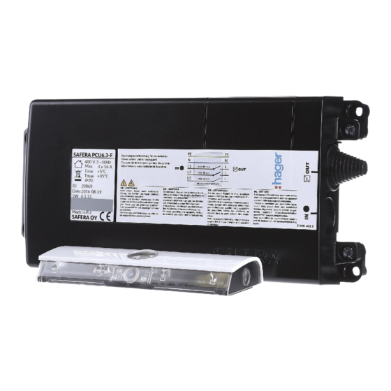
2 Geräteaufbau Bild 1: Ansicht Sensoreinheit (10) (11) (12) Bild 2: Ansicht Spannungsunterbrechung (1) Bedientaste 1 (8) Montagehalterung mit Klebeband (2) Bedientaste 2 (9) Spannungsunterbrechung (3) Bedientaste 3 (10) Einführung für Anschlussleitung Herd/Kochfeld (4) Sensoren (11) Ausbrechöffnung und Leitungseinführung (5) Status-LED für potenzialfreie Kontakte (AUX) (6) Frontabdeckung (12) Anschlussbuchse für Wasser Leckage Sensor... -
Page 5: Lieferumfang
Lieferumfang - Spannungsunterbrechung - 10 Farbstreifen zur Einlage in die transpa- rente Frontabdeckung - Sensoreinheit mit Montagehalterung - 2 Batterien für die Sensoreinheit (AA/LR6) - weiße Frontabdeckung für die Sensoreinheit (vormontiert) - 2 Verbindungsklemmen für N- und PE-Leiter Anschluss (3phasig) - transparente Frontabdeckung für die Sen- soreinheit - 1 Verbindungsklemme PE-Leiter Anschluss... -
Page 6: Bedienung
4 Bedienung Bedienkonzept und Anzeigeelemente über LEDs und Signaltöne über die Alarmsi- tuation. Hierzu verfügt das Gerät über eine Das Gerät schaltet im Alarmfall den Elektroherd, Batteriestatus-LED (7), eine Status-LED (5), drei das Kochfeld ab und informiert den Benutzer Bedientasten (1 ... 3) und zwei Sensoren (4). Farbe der Status-LED (5) Signalton Funktion... -
Page 7: Automatische Kindersicherung
4.2 Automatische Kindersicherung Kindersicherung ausschalten Die automatische Kindersicherung ist stan- dardmäßig deaktiviert. Bedientaste (1) 5 Sekunden gedrückt halten. „ Ein tiefer Signalton (●) ertönt und die Kindersicherung einschalten Status-LED blinkt rot. Kindersicherung ist Bedientaste (1) 5 Sekunden gedrückt halten. „ ausgeschaltet. -
Page 8: Wasser Leckage Sensor (Optional)
4.5 Wasser Leckage Sensor (optional) Der Herdwächter kann optional mit bis zu vier Signalton und blinkende Status-LED (5) „ Wasser Leckage Sensoren in seinen Funktio- erloschen. nen erweitert werden. Wenn die Sensoren mit Stromzufuhr ausschalten. „ Wasser in Berührung kommen, wird ein Wasser Ursache der Wasser Leckage beseitigen. - Page 9 AUX1 AUX 2 System Status Alarm! Eine gefährliche Situation ist erkannt und der Herdwächter schaltet die Stromzufuhr bei Gefahr, Zeitüberschreitung oder überhöhten Temperaturen ab. Der Alarmzustand wird ebenfalls aktiviert, wenn der Wasser Leckage Sensor ausgelöst hat, auch wenn die Stromversorgung des Herdes/Kochfel- des in diesem Fall nicht unterbrochen wird.
-
Page 10: Informationen Für Die Elektrofachkraft
5 Informationen für die Elektrofachkraft 5.1 Montage und elektrischer Anschluss Anwendungsberatung oder ihr Technisches Bei weitergehenden Fragen zur Anwendung Service Center kontaktieren. und Inbetriebnahme bitte die Technische GEFAHR! ç Elektrischer Schlag bei Berühren spannungsführender Teile. Elektrischer Schlag kann zum Tod führen. Vor Arbeiten am Gerät Anschlussleitungen freischalten und spannungsführende Teile in der Umgebung abdecken! (13) - Page 11 (20) (18) (19) (26) (11) 5 x 2,5 mm (10) (25) (27) (12) (21) (24) (22) (23) Bild 4: Anschlussbelegung 3phasig (28) (23) L OUT (26) (30) 3 x 6 mm (29) (10) (22) Bild 5: Anschlussbelegung 1phasig (19) Anschlussklemme L3 (26) Zugentlastung (20) Anschlussklemme L2 (27) Anschlussleitung 3phasig Herd/Kochfeld...
- Page 12 Spannungsunterbrechung anschließen Anschlussleitung (27) durch die Kabeleinfüh- „ rung (10) stecken. Leitungsschutzschalter für Herd/Kochfeld „ Zugentlastung (26) herstellen. ausschalten. „ Anschlussleitung 3phasig (27) an die An- Befestigungsschrauben (14) des Gehäuse- „ „ schlussklemmen OUT (19 ... 23) der Span- deckels (13) lösen und Deckel entfernen. nungsunterbrechung anschließen.
- Page 13 Potenzialfreie Kontakte anschließen Sensoreinheit - Montageort auswählen Das Gerät ist mit zwei potenzialfreien Ausgän- Die Sensoreinheit kann wahlweise an der gen AUX1 und AUX2 (18) ausgestattet. Darüber Wand oberhalb des Herdes/Kochfeldes oder kann der Zustand des Herdwächters an Bi- direkt unter die Dunstabzugshaube (Bild 8) näreingänge der Hausautomation oder sonstige montiert werden.
- Page 14 (32) (11) (31) (33) (32) Bild 9: Montage Wasser Leckage Sensor (31) Stecker Wasser Leckage Sensor (33) Anschlussbuchse für weiteren Wasser Leckage Sensor (32) Wasser Leckage Sensor Montage Wasser Leckage Sensor Optional: Weiteren Wasser Leckage Sensor „ an die Buchse (33) des vorderen Sensors Die Leckage Sensoren werden unter der Spüle, (31) stecken.
-
Page 15: Inbetriebnahme Und Funktionsprüfung Durchführen
5.2 Inbetriebnahme und Funktionsprüfung durchführen Nach der Installation sollte eine Funktionsprü- Bei einem Induktionsherd ist zur Inbetriebnahme fung durch die Elektrofachkraft durchgeführt ein geeigneter Topf aufzustellen. Bedientaste werden. (3) 5 s lang gedrückt halten. Für die Erstinbetriebnahme sind die Stan- Die Stromzufuhr zum Herd/Kochfeld wird un- dardeinstellungen des Herdwächters zu ver- terbrochen. - Page 16 Farbe der Anzahl der Alarmgrenze Installationshöhe: Installationshöhe: Status-LED (5) Signaltöne Wandmontage Montage unter der Dunstabzugshaube ●●● ●●● ●●● ●● ●●● ● ●●● ●● ● 45 ... 55 cm ●●● ●●● 50 ... 60 cm 55 ... 65 cm (Standard)* ●●● ●● 65 ...
- Page 17 oder Bild 10:Herdtyp manuell kalibrieren Einstellmodus 3: Herdtyp kalibrieren Die Herdüberwachung beendet den automa- tischen Einstellmodus. Der Einstellmodus 3 ist aufgerufen. Die Sta- Bei einem Induktionsherd ist zur Inbetriebnahme tus-LED (5) blinkt gelb-grün. ein geeigneter Topf aufzustellen. Zur Kalibrierung des Herdtyps stehen zwei Optionen zur Auswahl.
-
Page 18: Farbstreifen Der Sensoreinheit Wechseln
5.4 Farbstreifen der Sensoreinheit wechseln Mit den mitgelieferten Farbstreifen kann die Sen- Beim Anbringen des Farbstreifens auf der soreinheit an die Wandfarbe angepasst werden. Sensoreinheit unbedingt darauf achten, dass kein Sensor verdeckt wird. Sensoreinheit vorsichtig von der Montage- „ halterung (8) abziehen. Transparente Frontabdeckung auf der Sen- „... -
Page 19: Abfrage Fehlerstatus
Stromzufuhr zum Herd wird abgeschaltet Ursache 2: Batterien falsch eingelegt. und sofort wieder eingeschaltet. Korrekte Position der Batterien laut Markie- rung am Boden des Batteriefachs prüfen Ursache: Spannungsunterbrechung ist falsch und ggf. korrigieren. angeschlossen. In der Tabelle 7 sind die evtl. auftretenden Feh- Anschluss der Herdzuleitung und Herdan- lermeldungen und deren Problembeschreibung schlussleitung auf richtige Klemmenbele-... - Page 20 Content Operating and assembly instructions .............. 21 1 Safety instructions ..................21 2 Design and layout of the device ..............22 3 Function ......................23 4 Operation ...................... 24 4.1 Setting alarm limit ................24 4.2 Automatic child lock ................25 4.3 Dangerous situations ................
-
Page 21: Operating And Assembly Instructions
Cookguard 1phase WXH21x Cookguard 3phase WXH20x Operating and assembly instructions This document is only valid for devices with manufacturing dates after 09/2019 1 Safety instructions Electrical equipment may only be installed The device is only intended for mains-pow- and assembled by a qualified electrician. Al- ered cookers/hobs. -
Page 22: Design And Layout Of The Device
2 Design and layout of the device Figure 1: View of sensor unit (10) (11) (12) Figure 2: View of power control unit (1) Operation button 1 (8) Mounting bracket with adhesive tape (2) Operation button 2 (9) Power control unit (3) Operation button 3 (10) Entry for connection cable cooker/hob... -
Page 23: Scope Of Delivery
Scope of delivery - Power control unit - 10 Colour strips for inserting in the transpa- rent front cover - Sensor unit with mounting bracket - 2 Batteries for the sensor unit (AA/LR6) - white front cover for the sensor unit (pre-as- sembled) - 2 connection terminals for N- and PE-con- ductor connection (3phase) -
Page 24: Function
4 Operation Operating concept and display about the alarm situation via LEDs and acoustic signals. For this purpose, the device has one elements battery status LED (7), one status LED (5), three In the event of an alarm, the device switches operating buttons (1 ... -
Page 25: Automatic Child Lock
4.2 Automatic child lock Switching off child lock The automatic child lock is deactivated by default. Keep the operation button (1) pressed for 5 „ seconds. Switching on child lock A low acoustic signal (●) sounds and the Keep the operation button (1) pressed for 5 „... -
Page 26: Water Leakage Sensor (Optional)
4.5 Water leakage sensor (optional) The cookguard functions can optionally be The acoustic signal and flashing status LED „ extended with up to four water leakage sensors. (5) went out. If the sensors come into contact with water, a Switch off power supply. „... - Page 27 AUX1 AUX 2 System status Alarm! A hazardous situation is detected and the cookguard switches off the power supply in case of danger, timeout or overheating. The alarm state is also activated when the water leakage sensor has tripped; even though the power supply of the cooker/hob is not interrupted in this case.
-
Page 28: Information For Electricians
5 Information for electricians 5.1 Installation and electrical connection Technical Application Adviser or your Techni- Should you have further questions on the cal Service Centre. use and commissioning, please contact the DANGER! ç Touching live parts can result in an electric shock. An electric shock can be lethal. - Page 29 (20) (18) (19) (26) (11) 5 x 2,5 mm (10) (25) (27) (12) (21) (24) (22) (23) Figure 4: Connection assignment 3-phase (28) (23) L OUT (26) (30) 3 x 6 mm (29) (10) (22) Figure 5: Connection assignment 1-phase (19) Connecting terminal L3 (26) Strain relief (20) Connecting terminal L2...
- Page 30 Connect power control unit Insert the connection cable (27) through the „ cable entry (10). Switch off circuit breaker for cooker/hob. „ Fix strain relief (26). „ Unscrew fastening screws (14) of the casing „ Connect the connection cable 3-phase (27) cover (13) and remove the cover.
- Page 31 Connect potential-free contacts Sensor Unit - Selecting installation location The device is equipped with two potential-free outputs AUX1 and AUX2 (18). This allows The sensor unit can optionally be mounted on forwarding of the state of the cookguard to the wall above the cooker/hob or directly under binary inputs of the building automation system the extractor hood (Figure 8).
-
Page 32: Commissioning And Performing A Functional Test
(32) (11) (31) (33) (32) Figure 9: Mounting water leakage sensor (31) Water leakage sensor plug (33) Connection socket for additional water leakage sensors (32) Water leakage sensor Mounting water leakage sensor Optional: Insert additional water leakage sen- „ sor into the plug (33) of the front sensor (31). The leakage sensors are positioned under the Testing water leakage sensor sink, in the area of the dishwasher and in addi-... -
Page 33: Manual Commissioning/Device Setting
5.3 Manual commissioning/Device setting Setting mode Setting Colour of status LED (5) Mode 1 Setting alarm limit lights up white Mode 2 Establishing radio connection flashes purple-blue Mode 3 Calibrating cooker type flashes yellow-green Mode 4 Set and test AUX connection flashes white (normal AUX mode) flashes red (reversed AUX mode) Tabele 5. - Page 34 Setting mode 1: Setting alarm limit The next lower alarm limit is set and the setting mode 1 is left. The alarm limit is preset to 6 in default state. The new alarm limit is displayed according This means that the sensor unit is mounted at to the data in Table 6 and signalled via the a height of 50 ...
-
Page 35: Changing Colour Strips Of The Sensor Unit
Setting mode 3: Calibrating cooker type With an induction cooker a suitable pot must be used for commissioning. Setting mode 3 is called up. The status LED (5) flashes yellow-green. Setting mode 4: Setting and testing Two selection options are available for calibrat- potential-free contacts ing the cooker type. -
Page 36: Appendix
6 Appendix 6.1 Technical data Sensor unit Rated voltage, 1phase 230 V Rated current, 1phase 1 x 25 A Battery type AA/LR6 Alkaline Conductor cross-section, 1phase 3 x 6 mm² Recommended battery type Duracell Ultra Energy consumption Power (MX1500) Degree of contamination Battery service life 3 ... -
Page 37: Accessories
Power supply to the cooker is switched Cause 2: Batteries are not inserted correctly. off and switched on again immediately. Check that the batteries are in the correct position according to the marking on the bot- Cause: Power control unit is connected incor- tom of the battery compartment and correct rectly. - Page 38 Sommaire Mode d'emploi et instructions de montage ............39 1 Consignes de sécurité .................. 39 2 Composition de l’appareil ................40 3 Fonction ......................41 4 Utilisation ...................... 42 4.1 Régler la limite d'alarme ..............42 4.2 Sécurité enfants automatique .............. 43 4.3 Situations dangereuses ...............
-
Page 39: Mode D'emploi Et Instructions De Montage
Gardien de cuisine 1phase WXH21x Gardien de cuisine 3phase WXH20x Mode d'emploi et instructions de montage Ce document est uniquement pour les appareils à partir de la date de fa- brication 09/2019 1 Consignes de sécurité L'installation et le montage d'appareils élec- L'appareil est uniquement destiné... -
Page 40: Composition De L'appareil
2 Composition de l’appareil Image 1 : vue de l'unité de détection (10) (11) (12) Image 2 : vue du coupe-tension (1) Bouton poussoir de commande 1 (8) Support de montage avec bande adhésive (2) Bouton poussoir de commande 2 (9) Coupe-tension (3) Bouton poussoir de commande 3 (10) Entrée pour câble de raccordement... -
Page 41: Contenu De L'emballage
Contenu de l'emballage - Coupe-tension - 10 bandes colorées à insérer dans l'habil- lage frontal transparent - unité de détection avec support de montage - 2 batteries pour l'unité de détection (AA/ - habillage frontal blanc pour l'unité de détec- LR6) tion (prémonté) - 2 bornes de jonction pour raccordement des... -
Page 42: Utilisation
4 Utilisation Éléments d'affichage et concept de informe l'utilisateur de la situation d'alarme au moyen de LED et de signaux sonores. L'appareil commande dispose d'une LED d'état de batterie (7), d'une En cas d'alarme, l'appareil met hors tension LED d'état (5), de trois boutons poussoirs de la cuisinière électrique / le plan de cuisson et commande (1 à... -
Page 43: Sécurité Enfants Automatique
4.2 Sécurité enfants automatique Désactiver la sécurité enfants La sécurité enfants automatique est désacti- vée par défaut. Maintenir le bouton poussoir de commande „ (1) enfoncé pendant 5 secondes. Enclencher la sécurité enfants Un signal sonore grave (●) retentit et la LED Maintenir le bouton poussoir de commande „... -
Page 44: Confirmation De L'alarme Par Effleurement De L'unité De Réception (En Option)
4.4 Confirmation de l'alarme par effleurement de l'unité de réception (en option) Afin d'annuler la préalarme ou rétablir l'alimen- env. 5 secondes jusqu'à ce qu'un signal tation électrique de la cuisinière, presser le bou- sonore retentisse. ton-poussoir de commande (3) par défaut. Une La LED d'état (5) de l'unité... - Page 45 AUX1 AUX 2 État système Aucune signalisation d'alarme ! ÉTEINT ÉTEINT Cuisinière éteinte ou aucune situation dangereuse Activité de cuisson détectée. Ce statut s'active dès que la cuisinière est allumée. Selon l'intensité de la cuis- son, le signal est désactivé après 1 à 30 minutes après la fin de la cuisson. Ce temps de retard peut être utilisé...
- Page 46 AUX1 / AUX 2 État système AUX1 AUX2 Out 1 Option 1 : Out 2 Si un signal 1 se rapporte à la sortie AUX1, une signalisation d'alarme s'affi- che. + 5 V Output Input AUX1 AUX2 Out 1 Out 2 Option 2 : Si un signal 1 se rapporte à...
-
Page 47: Informations Destinées Aux Électriciens
5 Informations destinées aux électriciens 5.1 Montage et raccordement électrique contacter le conseil d'application technique Pour toute question approfondie concernant ou le centre d'assistance technique. l'application et la mise en service, merci de DANGER! ç Choc électrique en cas de contact avec les parties sous tension. Un choc électrique peut provoquer la mort. - Page 48 (20) (18) (19) (26) (11) 5 x 2,5 mm (10) (25) (27) (12) (21) (24) (22) (23) Image 4 : affectation des conducteurs 3phase (28) (23) L OUT (26) (30) 3 x 6 mm (29) (10) (22) Image 5 : affectation des conducteurs 1phase (19) Borne de raccordement L3 (26) Support de câble (20) Borne de raccordement L2...
-
Page 49: Raccorder Le Coupe-Tension
Raccorder le coupe-tension Enficher le câble de raccordement (27) dans „ l'arrivée de câbles (10). Couper le disjoncteur pour la cuisinière / le „ Mettre en place un support de câble (26). plan de cuisson. „ Raccorder le câble de raccordement 3phase Dévisser les vis de fixation (14) du couvercle „... -
Page 50: Unité De Détection - Choix Du Lieu De Montage
AUX1 AUX2 (11) In 1 Out 2 In 2 Out 1 Image 6 : borne de raccordement (AUX) pour Image 7 : raccorder une sortie libre de potentiel transmetteur de signal externe Raccorder des contacts libres de Unité de détection - Choix du lieu de potentiel montage L'appareil est équipé... -
Page 51: Montage Du Capteur De Fuite D'eau
+/- 8° +/- 8° max. max. 15 cm 15 cm 50 - 60 cm 55 - 65 cm (45 - 85 cm)* * Pour une installation hors hauteur standard de 55 à 65 cm, la limite d'alarme doit être adaptée en conséquence (voir Réglage de la limite d'alarme). -
Page 52: Mise En Service Et Réaliser Des Essais De Fonctionnement
5.2 Mise en service et réaliser des essais de fonctionnement Après l'installation, un électricien qualifié doit L'alimentation électrique de la cuisinière / du contrôler le bon fonctionnement. plan de cuisson est coupée. La cuisinière / le plan de cuisson est éteint. Pour la première mise en service, utiliser les réglages standard du gardien de cuisine. -
Page 53: Mode De Réglage 2 : Établir La Connexion Radio
Couleur de la Nombre de Limite Hauteur de Hauteur de l'installati- LED d'état (5) signaux d'alarme l'installation : on : montage sous la sonores montage mural hotte d'aspiration ●●● ●●● ●●● ●● ●●● ● Rouge ●●● ●● ● 45 ... 55 cm ●●●... - Page 54 oder Image 10 : calibrer manuellement le type de cuisinière Mode de réglage 3 : calibrer le type de Avec une cuisinière à induction, placer sur la cuisinière plaque une casserole adaptée pour la mise en service. Le mode de réglage 3 est affiché. La LED d'état (5) clignote en jaune-vert.
-
Page 55: Changer Les Bandes Colorées De L'unité De Détection
5.4 Changer les bandes colorées de l'unité de détection Avec les bandes colorées fournies, l'unité de En appliquant la bande colorée sur l'unité de détection peut être assortie à la couleur du mur. détection, faire particulièrement attention à ne masquer aucun capteur. Retirer avec précaution l'unité... -
Page 56: Aide En Cas De Problème
6.2 Aide en cas de problème L'alimentation électrique de la Passer manuellement la connexion radio en mode de réglage 2 (voir Mise en service cuisinière est déconnectée. manuelle). Cause 1 : le niveau de chargement des batteries Cause 4 : le coupe-tension est en surchauffe et de l'unité... -
Page 57: Accessoires
Remarque : détection et la désactivation des fusibles de Si un problème ne peut être résolu immé- la cuisinière pendant 10 secondes, puis par diatement, la cuisinière peut être utilisée leur réactivation. temporairement pendant 1,5 heure à tout Avec ce mode d'urgence, la fonction de pro- moment par le retrait des piles de l'unité... - Page 58 Inhoud Bedienings- en montagehandleiding ............... 59 1 Veiligheidsinstructies ..................59 2 Opbouw van het apparaat ................60 3 Functie ......................61 4 Bediening...................... 62 4.1 Alarmgrens instellen ................62 4.2 Automatische kinderbeveiliging ............63 4.3 Gevaarlijke situaties ................63 4.4 Alarm bevestigen door op de sensorunit te tikken (optioneel) ..... 63 4.5 Watermelder (optioneel) ..............
-
Page 59: Bedienings- En Montagehandleiding
Fornuisbewaker 1-fasig WXH21x Fornuisbewaker 3-fasig WXH20x Bedienings- en montagehandleiding Dit document is uitsluitend bedoeld voor apparaten met een fabricageda- tum vanaf september 2019 1 Veiligheidsinstructies Inbouw en montage van elektrische appara- Het apparaat is uitsluitend bedoeld voor tuur mag alleen door een installateur wor- elektrische fornuizen/kookplaten. -
Page 60: Opbouw Van Het Apparaat
2 Opbouw van het apparaat Afbeelding 1: aanzicht sensoreenheid (10) (11) (12) Afbeelding 2: aanzicht spanningsonderbreker (1) Bedieningstoets 1 (8) Montagehouder met tape (2) Bedieningstoets 2 (9) Spanningsonderbreker (3) Bedieningstoets 3 (10) Invoer voor aansluitleiding fornuis/kookplaat (4) Sensoren (11) Uitbreekopening en kabeldoorvoer voor (5) Status-led potentiaalvrije contacten (AUX) (6) Frontplaat... -
Page 61: Producteigenschappen
Leveringsomvang - Spanningsonderbreker - 10 gekleurde stroken om in de transparante frontplaat te plaatsen - Sensorunit met montagehouder - 2 batterijen voor de sensorunit (AA/LR6) - Witte frontplaat voor de sensorunit (voorge- monteerd) - 2 verbindingsklemmen voor aansluiting N- en PE-draad (3-fasig) - Transparante frontplaat voor de sensorunit - 1 verbindingsklem voor aansluiting PE-draad - Bevestigingsmateriaal... -
Page 62: Functie
4 Bediening Bedieningsconcept en de gebruiker via leds en akoestische signalen op de hoogte van de alarmsituatie. Daarvoor is het aanwijselementen apparaat voorzien van een batterijstatus-led (7), Het apparaat schakelt in geval van een alarm een status-led (5), drie bedieningstoetsen (1 … het elektrische fornuis/de kookplaat uit en brengt 3) en twee sensoren (4). -
Page 63: Automatische Kinderbeveiliging
4.2 Automatische kinderbeveiliging Kinderbeveiliging uitschakelen De automatische kinderbeveiliging is stan- daard gedeactiveerd. Bedieningstoets (1) 5 seconden lang inge- „ drukt houden. Kinderbeveiliging inschakelen Er weerklinkt een lage signaaltoon (●) en de Bedieningstoets (1) 5 seconden lang inge- „ status-led knippert rood. De kinderbeveili- drukt houden. -
Page 64: Watermelder (Optioneel)
4.5 Watermelder (optioneel) De functies van de fornuisbewaker kunnen De signaaltoon en de knipperende status-led „ optioneel met tot wel vier watermelders worden (5) gaan uit. uitgebreid. Als de sensoren in aanraking komen Stroomtoevoer onderbreken. „ met water, wordt een waterlekkage-alarm afge- De oorzaak voor de waterlekkage opheffen. - Page 65 AUX1 AUX 2 Systeemstatus Alarm! Er is een gevaarlijke situatie gedetecteerd en de fornuisbewaker onderbreekt de stroomtoevoer bij gevaar, tijdsoverschrijding of verhoogde temperaturen. De alarmtoestand wordt tevens geactiveerd, wanneer de wa- terlekkagesensor is geactiveerd, ook wanneer de voedingsspanning van het fornuis/de kookplaat in dit geval niet wordt onderbroken.
-
Page 66: Informatie Voor De Elektrotechnisch Installateur
5 Informatie voor de elektrotechnisch installateur 5.1 Montage en elektrische aansluiting de technische adviesdienst of uw technisch Bij meer vragen over het gebruik en de service center. ingebruikname kunt u contact opnemen met GEVAAR! ç Gevaar voor elektrische schokken bij aanraking van spanningsvoerende delen. Elektrische schokken kunnen de dood tot gevolg hebben. - Page 67 (20) (18) (19) (26) (11) 5 x 2,5 mm (10) (25) (27) (12) (21) (24) (22) (23) Afbeelding 4: bezetting van de aansluitingen 3-fasig (28) (23) L OUT (26) (30) 3 x 6 mm (29) (10) (22) Afbeelding 5: bezetting van de aansluitingen 1-fasig (19) Aansluitklem L3 (26) trekontlasting (20) Aansluitklem L2...
- Page 68 Spanningsonderbreker aansluiten Aansluitleiding (27) door de kabelinvoer (10) „ leiden. Installatie-automaat voor het fornuis/de „ Trekontlasting (26) tot stand brengen. kookplaat uitschakelen. „ De aansluitleiding 3-fasig (27) op de Bevestigingsschroeven (14) van het deksel „ „ aansluitklemmen OUT (19 … 23) van de van de behuizing (13) losdraaien en het spanningsonderbreker aansluiten.
- Page 69 AUX1 AUX2 (11) In 1 Out 2 In 2 Out 1 Afbeelding 6: aansluitklem (AUX) voor externe Afbeelding 7: Potentiaalvrije uitgang aansluiten signaalgevers Potentiaalvrije contacten aansluiten Sensorunit - montageplaats kiezen Het apparaat is uitgevoerd met twee potentiaal- De sensorunit kan naar keuze op de muur bo- vrije uitgangen AUX1 en AUX2 (18).
- Page 70 +/- 8° +/- 8° max. max. 15 cm 15 cm 50 - 60 cm 55 - 65 cm (45 - 85 cm)* * Bij een andere hoogte dan de standaardhoogte van 55 … 65 cm moet de alarmgrens overeen- komstig worden aangepast (zie Alarmgrens instellen). Afbeelding 8: wandmontage (links);...
-
Page 71: Montage Watermelder
Montage watermelder Optioneel: aanvullende watermelder in de „ bus (33) van de voorste melder (31) steken. De lekkagesensoren worden onder de spoelbak Watermelder testen: in de buurt van de vaatwasser aangebracht en op andere plaatsen waar een waterlekkage zou Een vochtige doek op de watermelder „... - Page 72 Handmatige inbedrijfstelling is vereist als het for- Bedieningstoets (2) gedurende 5 seconden „ nuis is vervangen, de afmetingen van het fornuis ingedrukt houden. of de montagehoogte van de sensorunit afwijken Instelmodus 1 is geactiveerd. De status-led van de standaardwaarden (afbeelding 8), of als er (5) licht wit op.
- Page 73 Instelmodus 1: Bedieningstoets (1) indrukken. „ Alarmgrens instellen De eerst volgende lagere alarmgrens wordt ingesteld en de instelmodus 1 wordt verlaten De fabrieksinstelling voor de alarmgrens is 6. Dat betekent dat de sensorunit op een hoogte De nieuwe alarmgrens wordt conform de van 50…...
- Page 74 Instelmodus 3: Fornuistype kalibreren Bij een inductiefornuis moet voor de inbedrijfstel- ling een geschikte pan op het fornuis worden Instelmodus 3 is geactiveerd. De status-led (5) geplaatst. knippert geel-groen. Voor het kalibreren van het fornuistype zijn Instelmodus 4: Potentiaalvrije twee opties beschikbaar. contacten instellen en testen Optie 1: Het fornuis en de oven zijn samen Aanvullende informatie over de beide poten-...
-
Page 75: Gekleurde Stroken Van De Sensorunit Vervangen
5.4 Gekleurde stroken van de sensorunit vervangen Met de meegeleverde gekleurde stroken kan Gekleurde strook naar keuze op de sen- „ de sensorunit aan de kleur van de muur worden sorunit aanbrengen. aangepast. Bij het aanbrengen van de gekleurde strook Sensorunit voorzichtig van de montage- op de sensorunit erop letten dat er geen „... -
Page 76: Hulp Bij Problemen
6.2 Hulp bij problemen Stroomtoevoer naar het fornuis is Draadloze verbinding via instelmodus 2 hand- matig tot stand brengen (zie Handmatige onderbroken. inbedrijfstelling). Oorzaak 1: de batterijstatus van de sensorunit is te Oorzaak 4: spanningsonderbreker is oververhit laag. Batterijstatusindicatie (7) knippert. en de status-led (5) knippert blauw (●●●). -
Page 77: Toebehoren
De status-led (5) knippert blauw Probleembeschrijving ● Probleem met de draadloze verbinding ●● Probleem met de spanningsonderbreker ●●● De spanningsonderbreker is oververhit De status-led (5) knippert geel Probleembeschrijving ● Probleem met de sensoren ●● Probleem met de sensorunit ●●● Onjuiste montagepositie van de sensorunit Tabel 7: foutmeldingen Opmerking: de zekeringen voor het fornuis 10 seconden... - Page 78 Contenuto Istruzioni d'uso e di montaggio ................ 79 1 Indicazioni di sicurezza................. 79 2 Struttura dell'apparecchio ................80 3 Funzione ....................... 81 4 Comando ...................... 82 4.1 Impostazione del limite di allarme ............83 4.2 Blocco di sicurezza per bambini automatico ........83 4.3 Situazioni pericolose ................
-
Page 79: Istruzioni D'uso E Di Montaggio
Sistema di controllo dei piani cottura monoase WXH21x Sistema di controllo dei piani cottura trifase WXH20x Istruzioni d'uso e di montaggio Questo documento non è destinato ad apparecchi a partire dalla data di produzione 09/2019 1 Indicazioni di sicurezza L'incasso e il montaggio degli apparecchi L'apparecchio è... -
Page 80: Struttura Dell'apparecchio
2 Struttura dell'apparecchio Figura 1: vista dell'unità sensore (10) (11) (12) Figura 2: vista dell'interruzione di tensione (1) Pulsante di comando 1 (8) Staffa di montaggio con nastro adesivo (2) Pulsante di comando 2 (9) Interruzione di tensione (3) Pulsante di comando 3 (10) Passacavo per linea di allacciamento cucina/piano cottura (4) Sensori... -
Page 81: Funzione
Fornitura - Interruzione di tensione - 10 strisce colorate per l'inserimento nella copertura frontale trasparente - Unità sensore con staffa di montaggio - 2 batterie per l'unità sensore (AA/LR6) - copertura frontale bianca per l'unità sensore (premontata) - 2 Morsetti di collegamento per attacco conduttore N e PE (3-fase) - copertura frontale trasparente per l'unità... -
Page 82: Comando
4 Comando Concetto di comando ed elementi di situazione di pericolo all'utente tramite LED e segnali acustici. A tale scopo, l'apparecchio è visualizzazione dotato di un LED di stato della batteria (7), un In caso di allarme, l'apparecchio disattiva la LED di stato (5), tre pulsanti di comando (1 ... -
Page 83: Impostazione Del Limite Di Allarme
4.1 Impostazione del limite di allarme Per la prima messa in funzione è necessario essere adattato in caso di falsi allarmi frequenti utilizzare l'impostazione standard. Per garantire (vedere la sezione Impostazioni manuali). A tale il funzionamento ottimale dell'apparecchio, il scopo, il limite di allarme andrebbe impostato limite di allarme può... -
Page 84: Conferma Allarme Mediante Tocco Dell'unità Sensore (Opzione)
4.4 Conferma allarme mediante tocco dell'unità sensore (opzione) Per interrompere il pre-allarme o per ripristinare Il LED di stato (5) dell'unità sensore lampeg- l'alimentazione di corrente alla cucina, si preme gia con luce gialla 3x quindi con luce rossa di norma il tasto di comando (3). In alternativa è anche possibile toccare semplicemente l'unità... -
Page 85: Contatti A Potenziale Libero (Opzione)
4.6 Contatti a potenziale libero (opzione) L'apparecchio è caratterizzato da due contatti Anche il segnale di uscita AUX può essere in- a potenziale libero AUX1 e AUX2 (Figura 6) ai vertito. Il segnale invertito può essere usato per quali per es. può essere collegato un ingresso esempio per riconoscere interruzione dei cavi binario radio KNX. - Page 86 AUX1 / AUX 2 Stato del sistema AUX1 AUX2 Out 1 Opzione 1: Out 2 se sull'uscita AUX1 è presente un segnale 1, viene visualizzato un messag- gio di allarme. + 5 V Output Input AUX1 AUX2 Out 1 Out 2 Opzione 2: se sull'uscita AUX2 è...
-
Page 87: Informazioni Per Gli Elettricisti
5 Informazioni per gli elettricisti 5.1 Montaggio e collegamento elettrico in funzione contattare la consulenza tecnica Per ulteriori domande sull'uso e sulla messa per l'uso o il centro di assistenza tecnica. PERICOLO! ç Scosse elettriche in caso di contatto con componenti sotto tensione. Le scosse elettriche possono provocare la morte. - Page 88 (20) (18) (19) (26) (11) 5 x 2,5 mm (10) (25) (27) (12) (21) (24) (22) (23) Figura 4: posa del collegamento trifase (28) (23) L OUT (26) (30) 3 x 6 mm (29) (10) (22) Figura 5: posa del collegamento monofase (19) Morsetto di collegamento L3 (25) Apertura aggiuntiva per montaggio a parete...
- Page 89 Collegamento dell'interruzione di ten- Inserire la linea di allacciamento (27) nella „ guida di inserimento del cavo (10). sione Effettuare il fissaggio cavo antistrappo (26). „ Disattivare l'interruttore di protezione per la „ cucina/il piano cottura. Cavo di collegamento 3-fase (27) ai morsetti „...
- Page 90 AUX1 AUX2 (11) In 1 Out 2 In 2 Out 1 Figura 6: morsetto di collegamento (AUX) per Figura 7: collegare l'uscita a potenziale libero generatori di segnale esterni Collegamento dei contatti a potenziale Unità sensore - selezione del luogo di libero montaggio L'apparecchio è...
- Page 91 +/- 8° +/- 8° max. max. 15 cm 15 cm 50 - 60 cm 55 - 65 cm (45 - 85 cm)* * In caso di installazione diversa dall'altezza standard di 55 ... 65 cm, il limite di allarme deve essere adattato di conseguenza (vedere sezione Impostazione del limite di allarme).
-
Page 92: Messa In Funzione E Verifica Delle Funzioni
Montaggio del sensore di perdita Opzione: inserire un altro sensore di perdita „ d'acqua nella presa (33) del sensore prece- d'acqua dente (31). I sensori di perdita vanno posizionati sotto al Controllare il sensore perdita acqua: lavello, in prossimità della lavastoviglie e in altri punti a rischio di perdite. - Page 93 Una messa in funzione manuale si rende Tenere premuto il pulsante di comando (2) „ necessaria in caso di sostituzione del piano cot- per 5 s. tura, se le dimensioni del piano cottura e l'altezza La modalità d'impostazione 1 è attivata. Il di montaggio dell'unità...
- Page 94 Modalità di impostazione 1: Il livello superiore desiderato viene imposta- to e la modalità d'impostazione 1 viene configurazione limite di allarme lasciata. Al momento della consegna, il limite di allarme Il nuovo limite di allarme è segnalato in base è preimpostato su 6. Ciò significa che l'unità alle indicazioni nella Tabella 6 mediante sensore è...
-
Page 95: Modifica Delle Strisce Colorate Dell'unità Sensore
Modalità di impostazione 3: Calibratura In caso di piano cottura a induzione, la messa in tipo di cucina funzione deve avvenire utilizzando una pentola adeguata. Viene richiamata la modalità d'impostazione 3. Il LED di stato (5) lampeggia in giallo-verde. Modalità di impostazione 4: Per la calibratura del tipo di piano cottura è... -
Page 96: Allegato
6 Allegato 6.1 Dati tecnici Unità sensore Tensione nominale, monofase 230 V Corrente nominale, monofase 1 x 25 A Tipo di batterie AA/LR6 alcaline Sezione conduttore, monofase 3 x 6 mm² Tipo batterie consigliate Duracell Ultra Power Consumo energetico (MX1500) Grado di inquinamento Durata batterie 3 ... -
Page 97: Accessori
L'alimentazione di corrente del piano Causa 2: batterie inserite in modo errato. cottura viene disattivata e subito Verificare la posizione corretta delle batterie ripristinata. in base all'indicazione sul fondo del vano batterie e, all'occorrenza, correggerla. Causa: l'interruzione di tensione è collegata in Nella tabella 7 sono elencate le segnalazioni modo errato. - Page 100 20918_04 www.hager.com 09/2019 - 6LE001605F...