Table des Matières
Publicité
Les langues disponibles
Les langues disponibles
Liens rapides
Harbor Breeze® is a registered trademark
of LF, LLC. All Rights Reserved.
Purchase Date
Questions, problems, missing parts? Before returning to your retailer, call our customer
service department at
PH19437
MAYFIELD
1-800-643-0067, 8 a.m. - 8 p.m., EST, Monday - Sunday.
1
ITEM
#0888716/61035000
0888715/61035001
0888714
CEILING FAN
MODEL
#C-BTH44ABZC5L
C-BTH44BNK5L
C-BTH44WW5L
Français p. 19
ATTACH YOUR RECEIPT HERE
JOIGNEZ VOTRE REÇU ICI
4009654
Publicité
Chapitres
Table des Matières
Dépannage

Manuels Connexes pour Harbor Breeze MAYFIELD C-BTH44ABZC5L


Sommaire des Matières pour Harbor Breeze MAYFIELD C-BTH44ABZC5L
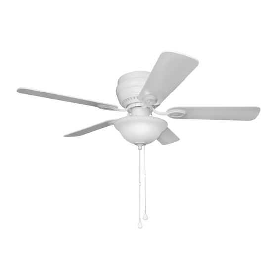
- Page 1 ITEM #0888716/61035000 0888715/61035001 0888714 MAYFIELD CEILING FAN MODEL #C-BTH44ABZC5L Harbor Breeze® is a registered trademark C-BTH44BNK5L of LF, LLC. All Rights Reserved. C-BTH44WW5L Français p. 19 ATTACH YOUR RECEIPT HERE JOIGNEZ VOTRE REÇU ICI 4009654 Purchase Date Questions, problems, missing parts? Before returning to your retailer, call our customer service department at 1-800-643-0067, 8 a.m.
-
Page 2: Table Des Matières
TABLE OF CONTENTS Safety Information ........................2 Package Contents ........................5 Hardware Contents ..........................6 Preparation ..........................6 Initial Installation ........................6 Installing Safety Cable ......................8 Wiring ............................9 Final Installation ........................11 Operating Instructions ......................15 Care and Maintenance ......................17 Troubleshooting ........................17 Limited Lifetime Warranty .......................18 Replacement Parts List ......................18 SAFETY INFORMATION READ AND SAVE THESE INSTRUCTIONS •... - Page 3 SAFETY INFORMATION WARNING To reduce the risk of fire, electrical shock or personal injury, mount fan to outlet box marked "ACCEPTABLE FOR FAN SUPPORT OF 35 LBS. (15.9 KG) OR LESS" and use mounting screws provided with the outlet box. Most outlet boxes commonly used for the support of lighting fixtures are not acceptable for fan support and may need to be replaced.
- Page 4 SAFETY INFORMATION CAUTION Modifications not approved by the party responsible for compliance could void the user's authority to operate the equipment. *NOTE: This equipment has been tested and found to comply with the limits for a Class B digital device, pursuant to Part 15 of the FCC Rules. These limits are designed to provide reasonable protection against harmful interference in a residential installation.
-
Page 5: Package Contents
PACKAGE CONTENTS PART DESCRIPTION QUANTITY PART DESCRIPTION QUANTITY Lock Washer Mounting Bracket (preassembled) + 1 extra Motor Housing Motor Housing Mounting Motor Assembly Screw (preassembled) Light Kit Fitter Hex Nut (preassembled) Glass Shade Mounting Bracket Flat Pull Chain Extension Washer (preassembled) Blade Motor Housing Lock Finial Plate (preassembled) -
Page 6: Hardware Contents
HARDWARE CONTENTS (shown actual size) Blade Fiber Screw Blade Qty. 1 Wire Washer Connector Qty. 15 + 1 extra Qty. 15 Qty. 4 + 1 extra PREPARATION Before beginning assembly of product, make sure all parts are present. Compare parts with package contents list and hardware contents list. - Page 7 INITIAL INSTALLATION This fan can be mounted as a flushmount on a regular (no-slope) ceiling only. Check to make sure blades (G) will be at least 30 in. 30 in. from any obstruction and at least 7 ft. above min. the floor.
-
Page 8: Installing Safety Cable
INITIAL INSTALLATION Remove motor screws (W) and lock washers (N) from underside of motor assembly (C) and save for blade arm (J) attachment later on. [If there are plastic motor blocks installed with the motor screws (W) and lock washers (N), discard the plastic motor blocks.] Plastic Motor Block... -
Page 9: Wiring
INSTALLING SAFETY CABLE Find a secure attachment point (wood ceiling joist Wood Screw, recommended) and secure safety cable (U) using Washer and a heavy-duty wood screw, washer and lock Lock Washer Loop washer (none included). NOTE: Extra cable slack can be left in ceiling area. - Page 10 WIRING 1b. FAN CONTROLLED BY PULL CHAIN, FAN CONTROLLED BY PULL CHAIN, LIGHT BY WALL SWITCH FAN AND LIGHT CONTROLLED BY TWO WALL SWITCHES LIGHT BY WALL SWITCH: If you intend to BLACK (WALL SWITCH) control the fan light with a separate wall switch, BLACK BLACK connect BLACK wire from fan to BLACK wire from...
-
Page 11: Final Installation
FINAL INSTALLATION 1. Remove motor assembly (C) from "J" hook. Align holes in motor assembly (C) with holes in mounting bracket (A). Secure motor assembly (C) with mounting bracket flat washers (Q) and mounting bracket nuts (S) previously removed (Step 3, page 7). 2. - Page 12 FINAL INSTALLATION Insert two motor screws (W) and lock washers (N) previously removed (Step 5, page 8) through one blade arm (J) to attach blade arm (J) to motor. Tighten motor screws (W) securely. Repeat with remaining blade arms (J), making sure to completely secure each blade arm (J) before proceeding with the next.
- Page 13 FINAL INSTALLATION To attach light kit fitter (D) to motor assembly (C), Switch Housing align holes in switch housing cap with holes in switch housing. (Make sure to align gap on top edge of the switch housing cap with the reverse switch on switch housing for the correct fit.) Re-insert switch housing cap screws (L) previously removed (Step 5, page 12).
- Page 14 FINAL INSTALLATION Attach applicable pull chain extensions (F) or custom pull chain extensions (not included) to the fan and light pull chains. Assembly is now complete. (For Fan) (For Light) If you do NOT wish to use the light kit, remove the hex nut (P) and 11 mm lock washer WHITE BLACK (K) from the threaded rod at the top of the light...
-
Page 15: Operating Instructions
FINAL INSTALLATION Attach fan pull chain extension (F) or custom pull chain extension (not included) to the fan pull chain. OPERATING INSTRUCTIONS The pull chain located on the switch housing Switch has four positions to control fan speed. One pull Housing is HIGH, two is MEDIUM, three is LOW and four turns the fan OFF. - Page 16 OPERATING INSTRUCTIONS 3. Use the fan reverse switch, located on the Switch switch housing, to optimize the fan for seasonal Housing performance. A ceiling fan will allow you to raise your thermostat setting in summer and lower your thermostat setting in winter without feeling a difference in your comfort.
-
Page 17: Care And Maintenance
CARE AND MAINTENANCE At least twice each year, lower motor housing (A) to check motor assembly (C), and then tighten all screws. Clean motor housing (A) with only a soft brush or lint-free cloth to avoid scratching the finish. Clean blades (G) with a lint-free cloth. You may occasionally apply a light coat of furniture polish to wood blades for added protection. -
Page 18: Limited Lifetime Warranty
LIMITED LIFETIME WARRANTY The distributor warrants this fan to be free from defects in workmanship and materials present at time of shipment from the factory for Lifetime limited from the date of purchase. This warranty applies only to the original purchaser. The distributor agrees to correct any defect at no charge or, at our option, replace the ceiling fan with a comparable or superior model. -
Page 19: Joignez Votre Reçu Ici
ARTICLE #0888716/61035000 0888715/61035001 0888714 VENTILATEUR DE PLAFOND MAYFIELD Harbor Breeze ® est une marque de commerce MODÈLE #C-BTH44ABZC5L déposée de LF, LLC. Tous droits réservés. C-BTH44BNK5L C-BTH44WW5L JOIGNEZ VOTRE REÇU ICI 4009654 Numéro de série Date d’achat Des questions, des problèmes, des pièces manquantes? Avant de retourner l’article au détaillant, appelez notre service à... -
Page 20: Consignes De Sécurité
TABLE DES MATIÈRES Consignes de sécurité ....................20 Contenu de l’emballage ....................23 Quincaillerie incluse ....................24 Préparation ......................... 24 Installation initiale ....................... 24 Installation du câble de sécurité ................. 26 Câblage ........................27 Installation définitive ....................29 Mode d’emploi ......................33 Entretien ........................ - Page 21 CONSIGNES DE SÉCURITÉ AVERTISSEMENT Afin de réduire les risques d’incendie, de choc électrique et de blessure, installez le ventilateur sur une boîte de sortie qui porte la mention « ACCEPTABLE FOR FAN SUPPORT OF 35 LBS (15.9 KG) OR LESS » (convient à un ventilateur de 15,9 kg [35 lb] ou moins) à...
- Page 22 CONSIGNES DE SÉCURITÉ ATTENTION Les modifications non autorisées expressément par la partie responsable de la conformité peuvent annuler le droit de l’utilisateur de se servir de cet appareil. * REMARQUE : Cet appareil a été testé et déclaré conforme aux limites imposées aux appareils numériques de classe B, conformément à...
-
Page 23: Contenu De L'emballage
CONTENU DE L’EMBALLAGE PIÈCE DESCRIPTION QUANTITÉ PIÈCE DESCRIPTION QUANTITÉ Support de fixation Rondelle de blocage (préassemblée) + 1 en surplus Boîtier de moteur Vis de montage du boîtier Ensemble de moteur de moteur (préassemblée) Dispositif de fixation de Écrou hexagonal (préassemblé) l’ensemble de luminaire Rondelle plate de support Abat-jour en verre... -
Page 24: Quincaillerie Incluse
QUINCAILLERIE INCLUSE (grandeur réelle) Capuchon Vis de pale Rondelle de pale en fibre Qté : 1 Qté : 15 Capuchon de + 1 en surplus Qté : 15 connexion + 1 en surplus Qté : 4 PRÉPARATION Avant de commencer l’assemblage de l’article, assurez-vous d’avoir toutes les pièces. Comparez le contenu de l’emballage avec la liste de la quincaillerie incluse. - Page 25 INSTALLATION INITIALE Ce ventilateur peut être monté au ras d’un plafond ordinaire (pas en pente) seulement. Vérifiez que les pales (G) sont situées à une 76,2 cm distance d’au moins 76,2 cm de toute obstruction min. et d’au moins 2,13 m du sol. 2,13 m min.
-
Page 26: Installation Du Câble De Sécurité
INSTALLATION INITIALE Retirez les vis de moteur (W) et les rondelles de blocage (N) du côté inférieur de l’ensemble de moteur (C). Conservez-les pour assembler les supports de pale (J) ultérieurement. (Si des cales de moteur en plastique sont jointes aux vis de moteur [W] et aux rondelles de blocage [N], jetez-les.) Cale de moteur... -
Page 27: Câblage
INSTALLATION DU CÂBLE DE SÉCURITÉ Repérez un point stable (nous vous recommandons Vis à bois, d’opter pour une solive de plafond en bois) et rondelle et rondelle de fixez-y le câble de sécurité (U) avec une vis à bois blocage Boucle robuste, une rondelle et une rondelle de blocage (non incluses). - Page 28 CÂBLAGE 1b. VENTILATEUR COMMANDÉ PAR UNE VENTILATEUR COMMANDÉ PAR UNE CHAÎNE ET LUMINAIRE COMMANDÉ PAR UN INTERRUPTEUR MURAL CHAÎNE ET LUMINAIRE COMMANDÉ PAR UN NOIR (INTERRUPTEUR MURAL) INTERRUPTEUR MURAL : si vous comptez commander le luminaire du ventilateur à l’aide d’un NOIR NOIR interrupteur mural distinct, raccordez le fil NOIR du...
-
Page 29: Installation Définitive
INSTALLATION DÉFINITIVE 1. Retirez l’ensemble de moteur (C) du crochet en J. Alignez les trous de l’ensemble de moteur (C) à ceux du support de fixation (A). Fixez l’ensemble de moteur (C) avec les rondelles plates du support de fixation (Q) et les écrous du support de fixation (S) précédemment retirés (étape 3, page 25). - Page 30 INSTALLATION DÉFINITIVE Insérez deux vis de moteur (W) et les rondelles de blocage (N) retirées précédemment (étape 5, page 26) à travers un support de pale (J) de façon à assembler ce dernier au moteur. Serrez fermement les vis de moteur (W). Faites de même pour les autres supports de pale (J).
- Page 31 INSTALLATION DÉFINITIVE Pour fixer le dispositif de fixation de l’ensemble de Boîtier de l’interrupteur luminaire (D) à l’ensemble de moteur (C), alignez les trous du couvercle du boîtier de l’interrupteur à ceux du boîtier de l’interrupteur. (Assurez-vous d’aligner l’ouverture du rebord supérieur du couvercle du boîtier de l’interrupteur à...
- Page 32 INSTALLATION DÉFINITIVE Fixez les rallonges de chaîne (F) fournies ou des rallonges de chaîne de votre choix (non incluses) aux chaînes du ventilateur et du luminaire. L’assemblage est terminé. (Pour le ventilateur) (Pour le luminaire) Si vous ne souhaitez PAS utiliser l’ensemble de luminaire, retirez l’écrou hexagonal (P) et la rondelle NOIR BLANC...
-
Page 33: Mode D'emploi
INSTALLATION DÉFINITIVE 13. Fixez la rallonge de chaîne (F) fournie ou une rallonge de chaîne de votre choix (non incluse) à la chaîne du ventilateur. MODE D’EMPLOI La chaîne du boîtier de l’interrupteur offre quatre Boîtier de réglages de la vitesse du ventilateur. Tirez une l’interrupteur fois pour une vitesse ÉLEVÉE, deux fois pour une vitesse MOYENNE, trois fois pour une... - Page 34 MODE D’EMPLOI 3. Utilisez l’interrupteur d’inversion du ventilateur, Boîtier de situé sur le boîtier de l’interrupteur, pour optimiser l’interrupteur le rendement du ventilateur en fonction de la saison. Un ventilateur de plafond permet d’augmenter le réglage de votre thermostat en été et de réduire son réglage en hiver sans nuire à...
-
Page 35: Entretien
ENTRETIEN Au moins deux fois par année, abaissez le boîtier de moteur (A) pour vérifier l’ensemble de moteur (C) et serrez toutes les vis. Nettoyez le boîtier de moteur (A) à l’aide d’une brosse douce ou d’un linge non pelucheux seulement afin d’éviter d’égratigner le fini. Nettoyez les pales (G) à l’aide d’un linge non pelucheux. -
Page 36: Garantie À Vie Limitée
DÉPANNAGE AVERTISSEMENT : Avant de commencer l’installation, coupez l’alimentation électrique pour éliminer les risques de choc électrique. PROBLÈME CAUSE POSSIBLE MESURE CORRECTIVE Le ventilateur 1. Les ampoules ne sont pas 1. Réinstallez les ampoules. fonctionne, mais installées correctement. pas le luminaire 2. -
Page 37: Liste Des Pièces De Rechange
LISTE DES PIÈCES DE RECHANGE Pour obtenir des pièces de rechange, communiquez avec notre service à la clientèle au 1 800 643-0067, entre 8 h et 20 h (HNE), du lundi au dimanche. #0888716/61035000 #0888715/61035001 #0888714 PIÈCE DESCRIPTION DE PIÈCE DE PIÈCE DE PIÈCE Support de fixation...