Publicité

Les langues disponibles

Les langues disponibles

Liens rapides

Compact 60
4
Bedienungsanleitung, User Manual , Mode d'emploi / 11/2021

Publicité

Table des Matières
loading

Sommaire des Matières pour AER Compact 604

  • Page 1 Compact 60 Bedienungsanleitung, User Manual , Mode d'emploi / 11/2021...
  • Page 2: Table Des Matières

    Der Compact 60/4 ist ein professionelles, kom- Soundingenieure erstaunt. paktes und leistungsfähiges Verstärkersystem, das speziell für die Verstärkung akustischer Alle AER-Verstärkersysteme sind dynamikkon- Instrumente entwickelt worden ist, sich aber trolliert, das bedeutet für Sie Zuverlässigkeit auch sehr gut für andere, auch elektrische und unverzerrte Wiedergabe auch bei hoher Instrumente eignet.
  • Page 3: Wichtige Sicherheitshinweise

    2. Wichtige Sicherheitshinweise Die folgenden Hinweise dienen der Minimierung des Verletzungsrisikos durch Feuer und Stromschlag. Das Blitzsymbol im gleich- Das Ausrufezeichen im C AU T I O N seitigen Dreieck soll den gleichseitigen Dreieck soll RISK OF ELECTRIC SHOCK DO NOT OPEN Benutzer vor unisolierter, den Benutzer auf wichtige AT T E N T I O N...
  • Page 4: Bedienelemente Und Anschlüsse

    3. Bedienelemente und Anschlüsse 13 14 15 e ects Compact 60 Compact 60 3.1 Frontseite input (ch. 1) Eingang Kanal 1, Klinkenbuchse 6,35 mm, Instrumenten- oder Line-Eingang high/low Abschwächer, high = Abschwächer aus, low = Abschwächer an clip Übersteuerungsanzeige gain Eingangspegel-Regler colour Schalter Klangfarben lter...
  • Page 5: Rückseite

    line out send tuner head return footswitch DI-out phones tip = int. fx 1 = gnd ring = ext. fx 2 = pos on/o 3 = neg 3.2 Rückseite 1) aux level 7) send Pegeleinsteller für aux in Ausgang für einen externen, parallelen E ektweg (siehe 5.2) in Verbindung mit return 2) aux in Aux-Eingang, 3,5-mm-Klinkenbuchse.
  • Page 6: Inbetriebnahme

    4. Inbetriebnahme • Wenn die gain-Einstellung zu niedrig ist, erreicht der Verstärker nicht die gewünschte 4.1 Anschließen und Einschalten Lautstärke, oder es macht sich störendes Überzeugen Sie sich Rauschen bemerkbar. bitte vor dem An- schluß an das Strom- • Bei zu hoher Einstellung treten hörbare netz davon, daß...
  • Page 7: E Ekte

    für Zupftechniken. Die Klangregelung kann die Die Intensität des externen E ekts wird durch Wirkung des colour-Filters unterstützen oder das externe E ektgerät bestimmt. mildern (siehe Abb. unten) Der externe E ektweg arbeitet parallel. Mit colour-Filter Parallel bedeutet, daß der E ektanteil (z.B. Hall) colour bass middle...
  • Page 8: Phantomspeisung

    5.4 Phantomspeisung Hinweise zur Benutzung der Phantomspei- sung 48-V-Phantomspeisung am Mikrofoneingang Phantomspeisung bedeutet Stromversorgung Mikrofone, die eine 48-V-Phantomspeisung eines Audiogeräts (z.B. Mikrofon) über die (P 48) erfordern, können über einen XLR-Ste- Audiokabelverbindung. cker direkt an input 2 angeschlossen werden. Schließen Sie an einen Eingang mit (einge- Die 48-V-Phantomspeisung ist im Ausliefe- schalteter) Phantomspeisung nur Geräte an, rungszustand aktiviert, kann aber durch eine...
  • Page 9: Technische Daten

    6. Technische Daten Kanal 1 Hochohmiger Instrumenten- / Line-Eingang, Max. Eingangsspannung: 5 V (+14 dBV) unsymmetrisch Eingangsimpedanz: 20 k Stereo-Klinkenbuchse*: ¼“ (6.35 mm) aux in Zusatzeingang, z.B. für CD Nenn-Eingangsspannung: 100 mV (–20 dBV) Stereo-Klinkenbuchse: 3,5 mm Abschwächer (high/low): –10 dB Nenn-Eingangsspannung: 500 mV (–6 dBV) Min.
  • Page 10 6. Technische Daten Klangregelung und Filter Maße und Gewicht Kanal 1 Maße colour bei 700 Hz –3 dB Höhe 260 mm (10,2“) bei 8 kHz +10 dB Breite 325 mm (12,8“) bass bei 100 Hz (shelf type) ±8 dB Tiefe 240 mm (9,45“) middle bei 800 Hz ±6 dB...
  • Page 11: Introduction

    The Compact 60/4 is a professional, compact and powerful ampli er system. Especially All AER ampli er systems employ dynamic developed for the enhancement of acoustic range control, which ensures reliability and low instruments it is nonetheless suitable for other distortion even at high volume despite striking- instruments, even electrical ones.
  • Page 12: Important Safety Instructions

    2. Important Safety Instructions The following guidelines shall help minimize the risk of injury through re or electric shock. The lightning ash with The exclamation point C AU T I O N the arrow head symbol within an equilateral RISK OF ELECTRIC SHOCK within an equilateral triangle is intended to DO NOT OPEN...
  • Page 13: Controls And Connections

    3. Controls and connections 13 14 15 e ects Compact 60 Compact 60 3.1 Front side 1) input (ch. 1) input channel 1, 1/4" (6,35 mm) jack socket, instrument or line input 2) high/low attenuator, high = att. o , low = att.
  • Page 14: Rear Side

    line out send tuner head return footswitch DI-out phones tip = int. fx 1 = gnd ring = ext. fx 2 = pos on/o 3 = neg 3.2 Rear side aux level send Level control for aux in Output for external, parallel e ect loop (see 5.2) in conjunction with return aux in return...
  • Page 15: Starting Up

    4. Starting up • If you use an instrument with a volume con- trol, start o with full volume but reduce it if 4.1 Cabling and switching on the clip indicator lights up early and the level Before connecting to adjustment is di cult.
  • Page 16: E Ects

    Center pos.: Please note: The tone controls have an e ect on the signal level. If the clip indicator ashes internal e ect on channel 1 + 2 more frequently, reduce the level a bit using external e ects on channel 1 + 2 the gain control (see also 4.2) Right stop: internal e ect on channel 2...
  • Page 17 9 V phantom power at line input The 9 V phantom power supplies instrument preamps with power (instead of a battery) that are prepared accordingly. Such preamps are connected to input 1 by a stereo jack cable. The phantom power can be switched on by the 9 V switch.
  • Page 18: Technical Speci Cations

    6. Technical speci cations Inputs Mono jack socket: ¼” (6.35 mm) Nom. input voltage: 320 mV (–10 dBV) channel 1 Instrument / line input, high impedance, Max. input voltage: 5 V (+14 dBV) unbalanced Input impedance: 20 k Stereo jack socket*: ¼“...
  • Page 19 6. Technical speci cations Footswitch connector Dimensions and weight footswitch Dimensions Connector for a dual footwitch Height 260 mm (10.20“) (dual, latching, toggle on-o switch) Width 325 mm (12.8“) Stereo jack socket: ¼” (6.35 mm) Depth 240mm (9.45“) Tip = internal e ect on/o Weight 7.1 kg (15.6 lbs) Ring = external e ect on/o...
  • Page 20: Introduction

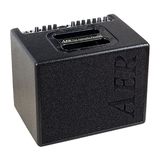
    Merci d’avoir choisi le Compact 60 l’instrumentation professionnelle. Le Compact 604 est un système d’ampli cation Tous les systèmes ampli cateurs AER utilisent professionnel, compact et puissant. Spécia- un contrôle de plage dynamique qui garantit lement développé...
  • Page 21: Mesures De Précautions

    2. Mesures de précautions Les conseils suivants vous aideront à minimiser les risques de blessures par brûlure ou choc électrique. Le symbole de l‘éclair avec Le symbole du point C A U T I O N la èche dans un triangle d‘exclamation dans un RISK OF ELECTRIC SHOCK équilatéral est conçu pour...
  • Page 22: Contrôles Et Connexions

    3. Bedienelemente und Anschlüsse 13 14 15 e ects Compact 60 Compact 60 3.1 Avant 1) input (ch. 1) Prise d‘entrée jack mono. 2) high/low Commutateur de sensibilité d’entrée, atténuateur = on 3) clip Indicateur d'ecrêtage 4) gain Contrôle du gain 5) colour Bouton pour ltre du timbre = on...
  • Page 23: Arriere

    line out send tuner head return footswitch DI-out phones tip = int. fx 1 = gnd ring = ext. fx 2 = pos on/o 3 = neg 3.2 Arriére aux level return Régulateur de niveau pour entrée auxiliaire (aux in) Entrée de la boucle d'e et externe parallèle.
  • Page 24: Mise En Service

    4. Mise en service Ces sources peuvent d‘abord être atténuées en appuyant sur le commutateur high/low 4.1 Raccordement et mise sous tension (canal 1). Avant de brancher Réglez ensuite le volume souhaité avec le l‘appareil au secteur, régulateur master. veuillez vous assurer que la tension de •...
  • Page 25: E Et

    et naturelle que vous pouvez modi er avec le à l‘ampli cateur. Pour ce faire, veuillez utiliser ltre de couleur. les prises send et return situées à l’arrière de l’ampli cateur (send va à l‘entrée, return vient Les médiums sont alors réduits et les aigus sont de la sortie du périphérique externe).
  • Page 26: Alimentation Fantôme

    5.4 Alimentation fantôme Remarque sur l’utilisation de l’alimentation fantôme Alimentation fantôme 48 V à l‘entrée du microphone L’alimentation fantôme fait référence à l‘ali- mentation d‘un appareil audio (par exemple Les microphones qui nécessitent une alimen- un microphone) via le raccordement du câble tation fantôme de 48 V (P 48) peuvent être audio.
  • Page 27: Donnée Techniques

    6. Donnée techniques Inputs Mono jack socket: ¼” (6.35 mm) Nom. input voltage: 320 mV (–10 dBV) channel 1 Instrument / line input, high impedance, Max. input voltage: 5 V (+14 dBV) unbalanced Input impedance: 20 k Stereo jack socket*: ¼“...
  • Page 28 6. Donnée techniques Footswitch connector Dimensions and weight footswitch Dimensions Connector for a dual footwitch Height 260 mm (10.20“) (dual, latching, toggle on-o switch) Width 325 mm (12.8“) Stereo jack socket: ¼” (6.35 mm) Depth 240mm (9.45“) Tip = internal e ect on/o Weight 7.1 kg (15.6 lbs) Ring = external e ect on/o...
  • Page 29: Blockschaltbild

    7. Blockschaltbild/block diagram/Schéma fonctionnel...
  • Page 32 Sales Sales Europe Africa, America, Asia, Oceania Version: 00100122 aer music gmbh aer ampli er gmbh Haberstrasse 46 Haberstrasse 46 D-42551 Velbert D-42551 Velbert info@aer-music.de info@aer-ampli er.com www.aer-music.de...

Ce manuel est également adapté pour:

The acoustic people compact 604 te

Table des Matières