Table des Matières
Publicité
Les langues disponibles
Les langues disponibles
Liens rapides
Evco S.p.A. • Code 104QX214000A00 • page 1/2
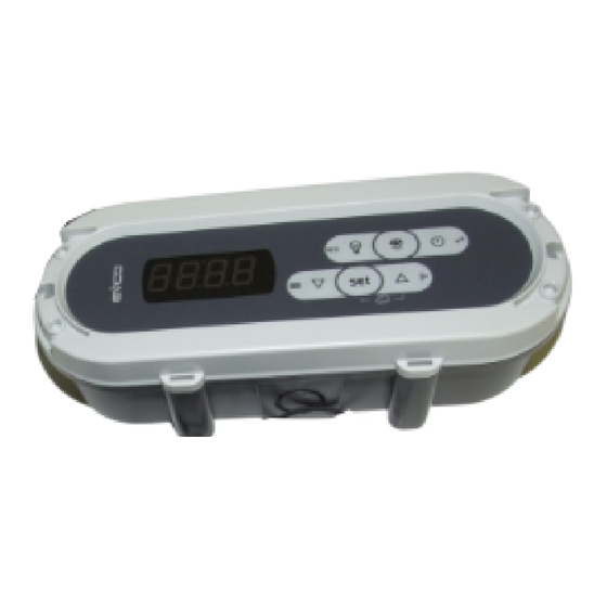
SMALL X
Cold room controllers
GB
ENGLISH
1
IMPORTANT
1.1
Important
Read these instructions carefully before installing and using the device and follow all additional information for installation and electrical connection; keep these instructions close to the device for future
consultations.
The device must be disposed according to the local legislation about the collection for electrical and electronic equipment.
2
SIZE AND INSTALLATION
2.1
Size
Size in mm (in).
To install the device operate as follows (please note covering a) and
covering b) are not symmetrical):
1.
Make two holes in the marks l).
2.
If you want the cables are inserted from the top or from the
bottom, make one hole in one of the marks m); if you want
the cables are inserted from the back, make a hole at the
back of the covering b).
3.
Make two holes Ø 6.0 mm (0.236 in) in the wall where you
want to install the device using the marks l) perforated as
reference.
4.
Insert the screw anchors j) in the holes of the wall.
5.
If you want the cables are inserted from the top or from the
bottom, assemble the fairlead f) in one of the marks m)
perforated.
6.
Insert the gaskets k) in the screws j).
7.
If you want the cables are inserted from the back, silicone
the back of the covering b) along the slot in relief and along
the two vertical segments.
8.
Fix the covering b) to the wall through the screws j) and
the gaskets k).
9.
Lean the covering a) to the covering b) and insert the
tongues d).
10.
Let the covering a) hanging, to allow operating inside the
device.
11.
Insert the connecting cables through the covering b).
12.
Make the electrical connection of the preassembed instru-
ment using the faston e) (look at the instructions of the
preassembled instrument).
13.
Apply the gasket i) in the covering b) positioning the ex-
tremities in the lower part of the covering.
14.
Lean the covering a) to the covering b) again and fix it
through the screws g) and the gaskets h).
15.
Apply the plugs c).
3
ELECTRICAL CONNECTION
3.1
Electrical connection
Look at the instructions of the preassembled instrument.
4
AVAILABLE CODES
4.1
Available codes
ASQX214000: cold room controller preassembled with EVX214N7
(alarm buzzer and serial port are supported), fixing bolts and nuts of
the instrument and polyester.
5
TECHNICAL DATA
5.1
Technical data
Box: self-extinguishing grey.
Frontal protection: IP 65.
Connections: 6.3 mm (0.248 in) wide faston (power supply and
outputs), screw terminal block (inputs), 6 poles connector (serial port).
Working temperature: from 0 to 55 °C (32 to 131 °F , 10 ... 90% of
relative humidity without condensate).
Power supply: 230 VAC, 50/60 Hz, 3 VA (approximate).
Also look at the instructions of the preassembled instrument.
I
ITALIANO
1
IMPORTANTE
1.1
Importante
Leggere attentamente queste istruzioni prima dell'installazione e prima
dell'uso e seguire tutte le avvertenze per l'installazione e per il collega-
mento elettrico; conservare queste istruzioni con il dispositivo per con-
sultazioni future.
Il dispositivo deve essere smaltito secondo le normative
locali in merito alla raccolta delle apparecchiature elettriche
ed elettroniche.
2
DIMENSIONI E INSTALLAZIONE
2.1
Dimensioni
Si veda il disegno del paragrafo 2.1 della sezione in Inglese.
Le dimensioni sono espresse in mm (in).
2.2
Installazione
Con riferimento al disegno del paragrafo 2.2 della sezione in Inglese, il
dispositivo è composto da:
a)
1 guscio frontale preassemblato con strumento, bulloni e
dadi di fissaggio dello strumento e poliestere
b)
1 guscio posteriore
c)
2 tappi copriviti di assemblaggio dei gusci
d)
2 linguette di assemblaggio dei gusci
e)
11 faston femmina a 90° e cappucci isolanti
f)
1 passacavo per tubo rigido Ø 20,0 mm (0,787 in)
g)
2 viti di assemblaggio dei gusci
h)
2 guarnizioni per viti di assemblaggio dei gusci
i)
1 guarnizione per guscio posteriore
j)
2 tasselli Ø 6,0 mm (0,236 in) da muro e relativi viti di fis-
saggio del guscio posteriore
k)
2 guarnizioni per viti di fissaggio del guscio posteriore
l)
tracce per fori per viti di fissaggio del guscio posteriore
m)
traccia per foro per passacavo per tubo rigido.
2.2
Installation
With reference to the following drawing, the device is made of:
a)
1 preassembled (instrument, fixing bolts and nuts of the
instrument and polyester) frontal covering
b)
1 back covering
c)
2 screw hider plugs assembling the coverings
d)
2 tongues assembling the coverings
e)
11 right angle female faston and insulating covers
f)
1 fairlead for Ø 20.0 mm (0.787 in) rigid pipe
g)
2 screws assembling the coverings
h)
2 gaskets for screws assembling the coverings
i)
1 gasket for back covering
j)
2 Ø 6.0 mm (0.236 in) wall screw anchors and screws fix-
ing the back covering
k)
2 gaskets for screws fixing the back covering
l)
marks for holes for screws fixing the back covering
m)
marks for hole for fairlead for rigid pipe.
Per installare il dispositivo operare nel modo indicato (si noti che il gu-
scio a) e il guscio b) non sono simmetrici):
1.
Effettuare due fori nelle tracce l).
2.
Se si desidera che i cavi vengano infilati dall'alto o dal bas-
so, effettuare un foro in una delle tracce m); se si desidera
che i cavi vengano infilati da dietro, effettuare un foro sul
retro del guscio b).
3.
Effettuare due fori Ø 6,0 mm (0,236 in) nella parete dove si
intende installare il dispositivo utilizzando le tracce l) forate
come guida.
4.
Infilare i tasselli j) nei fori della parete.
5.
Se si desidera che i cavi vengano infilati dall'alto o dal bas-
so, assemblare il passacavo f) in una delle tracce m) forata.
6.
Infilare le guarnizioni k) nelle viti j).
7.
Se si desidera che i cavi vengano infilati da dietro, siliconare
il retro del guscio b) lungo l'asola in rilievo e lungo i due
segmenti verticali.
8.
Fissare il guscio b) alla parete attraverso le viti j) e le guarni-
zioni k).
9.
Appoggiare il guscio a) al guscio b) e infilare le linguette d).
10.
Lasciare il guscio a) a sbalzo, per poter operare all'interno
del dispositivo.
11.
Infilare i cavi di collegamento nel guscio b).
12.
Effettuare il collegamento elettrico dello strumento
preassemblato utilizzando i faston e) (si vedano anche le
istruzioni dello strumento preassemblato).
13.
Applicare la guarnizione i) nel guscio b) posizionandone le
estremità nella parte inferiore del guscio.
14.
Applicare nuovamente il guscio a) al guscio b) e fissarlo
attraverso le viti g) e le guarnizioni h).
15.
Applicare i tappi c).
3
COLLEGAMENTO ELETTRICO
3.1
Collegamento elettrico
Si vedano le istruzioni dello strumento preassemblato.
4
CODICI DISPONIBILI
4.1
Codici disponibili
ASQX214000: frontecella preassemblato con EVX214N7 (il buzzer
di allarme e la porta seriale sono supportati), bulloni e dadi di fissaggio
dello strumento e poliestere.
5
DATI TECNICI
5.1
Dati tecnici
Contenitore: autoestinguente grigio.
Grado di protezione del frontale: IP 65.
version 1.00
Publicité
Table des Matières

Manuels Connexes pour Evco SMALL X


Sommaire des Matières pour Evco SMALL X
- Page 1 Evco S.p.A. • Code 104QX214000A00 • page 1/2 SMALL X Cold room controllers version 1.00 ENGLISH IMPORTANT Important Read these instructions carefully before installing and using the device and follow all additional information for installation and electrical connection; keep these instructions close to the device for future consultations.
- Page 2 Evco does not take any responsibility about damages coming by the non-observance of additional information. info@evco.it • www.evco.it Evco reserves the right to make any change without prior notice and at any time without prejudice the basic safety and operating features.
- Page 3 Among the several features one also highlights: Evco è inoltre in grado di fornire interfacce seriali isolate e sonde di temperatura / Evco can also supply insulated serial interfaces and temperature probes. supervisione di impianti RICS o al dispositivo per la registrazione di dati, per il download di dati...
- Page 4 Caratteristiche principali / Main features Dimensioni e installazione / Size and installation Dimensioni in mm (in) / Size in mm (in) L'installazione è prevista a retro pannello,con viti prigioniere M3 / Installation is by back-panel,with M3 threaded studs. Interfaccia utente (scheda a giorno) / User interface (open frame board) EVX201 EVX203 EVX204...
- Page 5 Evco S.p.A. • Code 104X201E314 • page 1/8 EVX Series Digital Controllers for Static and Ventilated Refrigeration Display Cabinets version 3.02 EN ENGLISH Operating Statuses: IMPORTANT • “on” status (the instrument is powered and on: the regulators can be Important switched on) Carefully read these instructions before installing and using the product.
- Page 6 Evco S.p.A. • Code 104X201E314 • page 2/8 4.8.1 Manual activation of operation for low or high If the keyboard is locked, the following are not permitted: To change a parameter: percentage of relative humidity (but EVX201 and • manual switch on/off of the instrument •...
- Page 7 Evco S.p.A. • Code 104X201E314 • page 3/8 • press and release the SET key or do not operate for 15 sec: the To manually restore the normal display: if it is flashing: display will show a flashing “- - - -” for 4 sec and the HACCP LED will •...
-
Page 8: Technical Data
Evco S.p.A. • Code 104X201E314 • page 4/8 • press a key to restore normal display Evaporator probe error (but EVX201) EVX204 and EVX214 digital outputs: 4 relays: Main consequnces: Solutions: • compressor relay: 30 A res. @ 250 • if the power supply interruption lasts longer than the •... - Page 9 Evco S.p.A. • Code 104X201E314 • page 5/8 WORKING SETPOINT AND CONFIGURATION PARAMETERS 12.1 Working setpoint MIN. MAX. EVX201 EVX203 EVX204/5 EVX214/5 WORKING SETPOINT °C/°F (1) -2.0 -18.0 -18.0 working setpoint; see also r0 12.2 Configuration parameters PAR. MIN. MAX.
-
Page 10: Temperature Alarms
Evco S.p.A. • Code 104X201E314 • page 6/8 - - - - not avail. number of evaporator temperature values used for the calculation of the relative average (for the defrost activation; only if d8 = 3); also look at r7, i11 and i12 3,000 min not avail. -
Page 11: Digital Outputs
Evco S.p.A. • Code 104X201E314 • page 7/8 maximum duration of the effect caused by activation of the door microswitch on the compressor and the evaporator fan (the evaporator fan in EVX203, EVX204, EVX214, EVX205 and EVX215 only) -1= the effect will last until the input is disactivated - - - - storage of door microswitch input alarm (code “id”) (20) -
Page 12: Preliminary Notes
Evco does not take any responsibility about damages coming by the non-observance of additional information. info@evco.it • www.evco.it Evco reserves the right to make any change without prior notice and at any time without prejudice the basic safety and operating features. - Page 13 Evco S.p.A. • Code 104X201F314 • page 1/8 Série EVX Dispositifs de contrôle numérique pour les armoires réfrigérées statiques et ventilées version 3.1 FRANÇAIS Il existe les positions de fonctionnement suivantes: IMPORTANT •la position "on" (l'instrument est alimenté et il est allumé: les régulateurs Important peuvent être allumés)
- Page 14 Evco S.p.A. • Code 104X201F314 • page 2/8 Durant le fonctionnement pour un haut pourcentage d'humidité 4.12.1 Activation/désactivation de la fonction Energy Il est en outre possible de configurer le point de consigne de travail à relative le ventilateur de l'évaporateur est toujours allumé.
- Page 15 Evco S.p.A. • Code 104X201F314 • page 3/8 CODE TYPE D'ALARME (VALEUR CRITIQUE) l'alarme s'est déclenchée en 2009 (continue...) LED ventilateur de l'évaporateur alarme d'une température minimum (la température l'alarme s'est déclenchée au mois de mars (continue...) si elle est allumée, le ventilateur de l'évaporateur sera mis minimum de la cellule durant l'alarme) l'alarme s'est déclenchée le 26 mars 2009...
- Page 16 Evco S.p.A. • Code 104X201F314 • page 4/8 ALARMES Conséquences principales: DONNÉES TECHNIQUES Alarmes • le compresseur et le ventilateur de l'évaporateur seront 11.1 Données techniques CODE SIGNIFICATION éteints Conteneur: fiche à jour. Alarme de température minimum (alarme HACCP) • la sortie de l'alarme sera activée (seulement si le paramètre Degré...
-
Page 17: Point De Consigne De Travail Et Paramètres De Configuration
Evco S.p.A. • Code 104X201F314 • page 5/8 POINT DE CONSIGNE DE TRAVAIL ET PARAMÈTRES DE CONFIGURATION 12.1 Point de consigne de travail MIN. MAX. U. M. EVX201 EVX203 EVX204/5 EVX214/5 POINT DE CONSIGNE DE TRAVAIL °C/°F (1) -2.0 -18.0 -18.0... -
Page 18: Alarmes De Température
Evco S.p.A. • Code 104X201F314 • page 6/8 - - - - pas disp. numéro des valeurs de la température de l'évaporateur utilisées pour le calcul de la moyenne respective (pour l'activation du dégivrage; seulement si 8 = 3); voir également r7, i11 et i12 3,000 min pas disp. -
Page 19: Réseau Sériel (Modbus)
Evco S.p.A. • Code 104X201F314 • page 7/8 retard signalisation alarme entrée du microrupteur de la porte (code “id”) -1= l'alarme ne sera pas signalée durée maximum de l'effet provoqué par l'activation de l'entrée du microrupteur de la porte sur le compresseur et sur le ventilateur de l'évaporateur (ce dernier seulement dans l'EVX203, dans l'EVX204, dans l'EVX214, dans l'EVX205 et dans l'EVX215) -
Page 20: Indications Préliminaires
Téléphone 0437-852468 • Fax 0437-83648 Evco ne peut être retenue responsable pour les dommages causés par l'inobservance des avertissements. info@evco.it • www.evco.it Evco se réserve le droit d'apporter toute modification sans préavis sans nuire aux caractéristiques essentielles de fonctionnement et de sécurité. - Page 21 Evco S.p.A. • Code 104X201G314 • Seite 1/8 Serie EVX digitale Controller für statische und belüftete Kühltheken version 3.1 DEUTSCH Es existieren die folgenden Betriebszustände: WICHTIG • der Status "on" (das Gerät ist stromversorgt und eingeschaltet: die Wichtig Regler können eingeschaltet werden) Lesen Sie diese Hinweise sorgfältig vor der Installation und vor dem Gebrauch und folgen Sie den Anweisungen für die Installation und dem...
- Page 22 Evco S.p.A. • Code 104X201G314 • Seite 2/8 Während des Betriebs für hohen relativen Luftfeuchtigkeitsanteil, ist 4.12.1 Aktivierung/Deaktivierung der Energy Saving- im Gange ist der Verdampferlüfter immer eingeschaltet. Funktion mit Wirkung allein auf den Kompressor • die Taste SET drücken und loslassen: die Kompressor-LED wird 4.8.1...
- Page 23 Evco S.p.A. • Code 104X201G314 • Seite 3/8 CODE ALARMART (KRITISCHER WERT) der Alarm ist 2009 aufgetreten (fährt fort...) Verdampferlüfter-LED Alarm Mindesttemperatur (die niedrigste Temperatur der der Alarm ist im Monat März aufgetreten (fährt fort...) wenn sie eingeschaltet ist, wird der Verdampferlüfter Zelle während des Alarms)
- Page 24 Evco S.p.A. • Code 104X201G314 • Seite 4/8 ALARME C7 festgelegten liegt, wird es notwendig sein, die TECHNISCHE DATEN Alarme Stromversorgung abzutrennen und den Kondensator 11.1 Technische daten CODE BEDEUTUNG zu reinigen Gehäuse: Offene Karte. Alarm Mindesttemperatur (HACCP-Alarm) Hauptauswirkungen: Schutzart frontseitig: IP 00.
- Page 25 Evco S.p.A. • Code 104X201G314 • Seite 5/8 ARBEITSSOLLWERT UND KONFIGURATIONSPARAMETER 12.1 Arbeitssollwert MIN. MAX. M.E. EVX201 EVX203 EVX204/5 EVX214/5 ARBEITSSOLLWERT °C/°F (1) -2.0 -18.0 -18.0 Arbeitssollwert; siehe auch r0 12.2 Konfigurationsparameter PAR. MIN. MAX. M.E. EVX201 EVX203 EVX204/5 EVX214/5 ARBEITSSOLLWERT °C/°F (1)
- Page 26 Evco S.p.A. • Code 104X201G314 • Seite 6/8 - - - - nicht verf. Anzahl der Temperaturwerte des Verdampfers, die für die Berechnung des relativen Mittelwertes verwendet werden (für die Aktivierung des Abtauens; nur, wenn d8 = 3); siehe auch r7, i11 und i12 3,000 min nicht verf.
- Page 27 Evco S.p.A. • Code 104X201G314 • Seite 7/8 Verzögerung Alarmsignal Mikroporteingang (Code “id”) -1= der Alarm wird nicht signalisiert werden maximale Dauer der durch die Aktivierung des Mikroporteingangs veranlassten Wirkung auf den Kompressor und Verdampferlüfter (letzterer nur im EVX203, EVX204, EVX214, EVX205 und EVX215) -1= die Wirkung hält an, bis der Eingang deaktiviert wird...
-
Page 28: Elektrischer Anschluss
Diese Veröffentlichung ist das alleinige Eigentum von Evco, das die Verbreitung untersagt, sofern nicht ausdrücklich durch Evco genehmigt. Via Mezzaterra 6, 32036 Sedico Belluno ITALIA Evco übernimmt keine Verantwortung für die in der vorliegenden Veröffentlichung aufgeführten Eigenschaften, technischen Daten und möglichen Fehler. - Page 29 Evco S.p.A. • Codice 104X201I314 • pag. 1/8 Serie EVX Controllori digitali per armadi refrigerati statici e ventilati versione 3.02 ITALIANO Esistono i seguenti stati di funzionamento: IMPORTANTE • lo stato “on” (lo strumento è alimentato ed è acceso: i regolatori...
- Page 30 Evco S.p.A. • Codice 104X201I314 • pag. 2/8 Durante il funzionamento per alta percentuale di umidità relativa il ven- 4.12.1 Attivazione/disattivazione della funzione Energy È inoltre possibile impostare il setpoint di lavoro attraverso il parametro tilatore dell’evaporatore è sempre acceso.
- Page 31 Evco S.p.A. • Codice 104X201I314 • pag. 3/8 CODICE TIPO DI ALLARME (VALORE CRITICO) l’allarme si è manifestato nel 2009 (continua ...) LED ventilatore dell’evaporatore allarme di temperatura di minima (la minima temperatura l’allarme si è manifestato nel mese di marzo (continua ...) se è...
- Page 32 Evco S.p.A. • Codice 104X201I314 • pag. 4/8 ALLARMI Principali conseguenze: DATI TECNICI Allarmi • il compressore e il ventilatore dell’evaporatore verranno 11.1 Dati tecnici CODICE SIGNIFICATO spenti Contenitore: scheda a giorno. Allarme di temperatura di minima (allarme HACCP) • l’uscita di allarme verrà attivata (solo se il parametro u1 Grado di protezione del frontale: IP 00.
- Page 33 Evco S.p.A. • Codice 104X201I314 • pag. 5/8 SETPOINT DI LAVORO E PARAMETRI DI CONFIGURAZIONE 12.1 Setpoint di lavoro MIN. MAX. U. M. EVX201 EVX203 EVX204/5 EVX214/5 SETPOINT DI LAVORO °C/°F (1) -2.0 -18.0 -18.0 setpoint di lavoro; si veda anche r0 12.2...
-
Page 34: Ventilatore Dell'evaporatore
Evco S.p.A. • Codice 104X201I314 • pag. 6/8 - - - - non disp. numero di valori della temperatura dell’evaporatore utilizzati per il calcolo della relativa media (per l’attivazione dello sbrinamento; solo se d8 = 3); si vedano anche r7, i11 e i12 3,000 min non disp. -
Page 35: Uscite Digitali
Evco S.p.A. • Codice 104X201I314 • pag. 7/8 ritardo segnalazione allarme ingresso micro porta (codice “id”) -1 = l’allarme non verrà segnalato durata massima dell’effetto provocato dall'attivazione dell’ingresso micro porta sul compressore e sul ventilatore dell’evaporatore (quest’ulti- mo solo nell’EVX203, nell’EVX204, nell’EVX214, nell’EVX205 e nell’EVX215) -1 = l’effetto durerà... -
Page 36: Cenni Preliminari
• per le riparazioni e per informazioni riguardanti lo strumento rivolgersi alla rete di vendita Evco. EVCO S.p.A. La presente pubblicazione è di esclusiva proprietà Evco la quale pone il divieto di divulgazione se non espressamente autorizzata da Evco stessa. Via Mezzaterra 6, 32036 Sedico Belluno ITALIA Evco non si assume alcune responsabilità... - Page 37 Evco S.p.A. • Código 104X201S314 • pág. 1/8 Serie EVX Revisores digitales para armarios refrigerados estáticos y ventilados versión 3.1 ESPAÑOL Existen los siguientes estados de funcionamiento: IMPORTANTE •el estado "on" (el instrumento es alimentado y está encendido: los 1.1 Importante reguladores pueden estar encendidos) Lea atentamente estas instrucciones antes de la instalación y antes del uso y siga todas las advertencias para la instalación y para la conexión...
- Page 38 Evco S.p.A. • Código 104X201S314 • pág. 2/8 Durante el funcionamiento por alto porcentaje de humedad relativa 4.12.1 Activación/desactivación de la función Energy Es además posible configurar el setpoint de trabajo mediante el el ventilador del evaporador está siempre encendido.
- Page 39 Evco S.p.A. • Código 104X201S314 • pág. 3/8 CÓDIGO TIPO DE ALARMA (VALOR CRITICO) la alarma se ha manifestado en el 2009 (continúa…) LED ventilador del evaporador alarma de temperatura mínima (la temperatura mínima de la alarma se ha manifestado en el mes de marzo (continúa…) si está...
- Page 40 Evco S.p.A. • Código 104X201S314 • pág. 4/8 ALARMAS Principales consecuencias: DATOS TÉCNICOS Alarmas • el compresor y el ventilador del evaporador se apagarán 11.1 Datos técnicos CÓDIGO SIGNIFICADO • la salida de alarma se activará (sólo si el parámetro u1 y/ Contenedor: ficha del día.
- Page 41 Evco S.p.A. • Código 104X201S314 • pág. 5/8 SETPOINT DE TRABAJO Y PARÁMETROS DE CONFIGURACIÓN 12.1 Setpoint de trabajo MÍN. MÁX. U. M. EVX201 EVX203 EVX204/5EVX214/5 SETPOINT DE TRABAJO °C/°F (1) -2.0 -18.0 -18.0 setpoint de trabajo; vea también r0 12.2...
-
Page 42: Entradas Digitales
Evco S.p.A. • Código 104X201S314 • pág. 6/8 - - - - no disp. número de valores de la temperatura del evaporador usados para el cálculo del promedio correspondiente (para la activación de la descongelación; sólo si d8 = 3); se vean también r7, i11 y i12 3,000 min no disp. - Page 43 Evco S.p.A. • Código 104X201S314 • pág. 7/8 retraso señalización alarma entrada micro puerto (código “id”) -1= la alarma no será señalada duración máxima del efecto provocado por la activación de la entrada micro puerto en el compresor y en el ventilador del evaporador (esto último sólo en EVX203, en EVX204, en EVX214, en EVX205 y en EVX215)
- Page 44 La presente publicación es de exclusiva propiedad Evco la cual prohíbe la divulgación si no está expresamente autorizada por Evco. Via Mezzaterra 6, 32036 Sedico Belluno ITALIA Evco no se asume ninguna responsabilidad en relación a las características, a los datos técnicos y a los posibles errores que se muestran en la presente. Teléfono 0437-852468 • Fax 0437-83648 Evco no se puede considerar responsable por daños causados por el incumplimiento de las advertencias.
- Page 45 Evco S.p.A. • Code 104X201D314 • pag. 1/8 EVX serie digitale controleapparatuur voor statische en geventileerde koelkasten versie 3.1 NEDERLANDS De interface kent de volgende functioneringswijzen: BELANGRIJK •"on" (het instrument is aangesloten en ingeschakeld: de regelaars BELANGRIJK kunnen geactiveerd worden) Lees voor de installatie en de ingebruikname deze aanwijzingen aandachtig door en neem de waarschuwingen voor de installatie en de •...
- Page 46 Evco S.p.A. • Code 104X201D314 • pag. 2/8 4.8.1 Functionering wegens laag of hoog percentage 4.13 Het toetsenbord blokkeren/deblokkeren De configuratieparameters instellen relatieve luchtvochtigheid tijdens handmatige Het toetsenbord blokkeren: De procedure opstarten: functionering (uitgezonderd EVX201 en als de • controleer of geen enkele procedure opgestart is •...
- Page 47 Evco S.p.A. • Code 104X201D314 • pag. 3/8 CODE SOORT ALARM (KRITIEKE WAARDE) het alarm heeft zich voorgedaan in 2009 (wordt vervolgd...) LED ventilator verdamper alarm minimum temperatuur (de minimum temperatuur alarm heeft zich voorgedaan maart aan, de ventilator van de verdamper is ingeschakeld in de cel tijdens het alarm) (wordt vervolgd...)
- Page 48 Evco S.p.A. • Code 104X201D314 • pag. 4/8 ALARMEN Belangrijkste consequenties: TECHNISCHE GEGEVENS Alarmen • de compressor en de ventilator van de verdamper 11.1 Technische gegevens CODE BETEKENIS worden uitgeschakeld Houder: dagkaart. Alarm minimum temperatuur (HACCP alarm) • de alarmuitgang wordt geactiveerd (uitsluitend als de Beschermingsgraad voorpaneel: IP 00.
- Page 49 Evco S.p.A. • Code 104X201D314 • pag. 5/8 SETPOINT EN CONFIGURATIEPARAMETERS 12.1 Setpoint MIN. MAX. U. M. EVX201 EVX203 EVX204/5 EVX214/5 SETPOINT °C/°F (1) -2.0 -18.0 -18.0 setpoint, zie ook r0 12.2 Configuratieparameters PAR. MIN. MAX. U. M. EVX201 EVX203 EVX204/5 EVX214/5 SETPOINT °C/°F (1)
-
Page 50: Digitale Ingangen
Evco S.p.A. • Code 104X201D314 • pag. 6/8 - - - - niet besc. aantal temperatuurwaarden van de verdamper die voor het berekenen van het relatieve gemiddelde gebruikt worden (voor het activeren van het ontdooien, uitsluitend als d8 = 3), zie r7, i11 en i12 3,000 min niet besc. - Page 51 Evco S.p.A. • Code 104X201D314 • pag. 7/8 vertraging signalering alarm ingang micro deur (code “id”) -1= het alarm wordt niet gesignaleerd maximum duur effect veroorzaakt door de activering van de ingang micro deur op de compressor en op de ventilator van de compressor...
-
Page 52: Inleidende Opmerkingen
Telefoon 0437-852468 • Fax 0437-83648 Evco acht zich niet verantwoordelijk voor schade veroorzaakt door de niet-inachtneming van de aanwijzingen. info@evco.it • www.evco.it Evco behoudt zich het recht voor zonder mededeling wijzigingen te verrichten die de essentiële functies en veiligheid niet zullen beïnvloeden.