Table des Matières
Publicité
Les langues disponibles
Les langues disponibles
Liens rapides
Publicité
Table des Matières

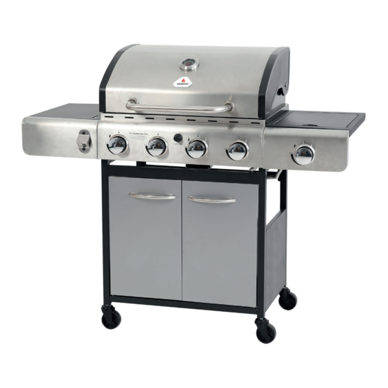
Manuels Connexes pour Kamino BBQ 131971


Sommaire des Matières pour Kamino BBQ 131971
- Page 1 131971_Kaminoflam_BBQ_Anleitung_DINA5_DE_EN_FR_IT_ES_132S.indd 1 18.12.19 10:01...
- Page 2 Inhaltsverzeichnis / Content / Contenu / Contenuto / Contenido Deutsch . . . . . . . . . . . . . . . . . . . . . . . . . . . . . . . . . . . . . . . . . . . . . . . . .3 English .
- Page 3 Montageanleitung 4-BRENNER GAS-GRILLWAGEN 131971_Kaminoflam_BBQ_Anleitung_DINA5_DE_EN_FR_IT_ES_132S.indd 3 18.12.19 10:01...
-
Page 4: Allgemeine Sicherheitshinweise
DE Sicherheitshinweise Lesen Sie die Bedienungsanleitung vor Inbetriebnahme des Gerätes . Lesen Sie sorgfältig und bewahren Sie die Anleitung für die weitere Verwendung auf! Sicherheitshinweise Allgemeine Sicherheitshinweise • Das Gerät darf nur im Freien benutzt werden! • Verwenden Sie hitzebeständige Grillhandschuhe (PSA Kat . - Page 5 DE Sicherheitshinweise • Drehen Sie alle Regler auf OFF sobald Sie Gasgeruch wahrnehmen! • Kontrollieren Sie sämtliche Verbindungsstellen zwischen Gasflasche und Gerät vor jedem Gebrauch. Benutzen Sie den Gasgrill nicht, wenn Sie Beschädigungen festgestellt haben! Gleiches gilt für den Gasschlauch! • Der Gasschlauch muss locker hängen, darf nicht unter Spannung stehen, geknickt oder verdreht werden . Kontrollieren Sie den Gasschlauch vor jeder Benutzung auf Risse oder sonstige Beschädigungen. Nicht benutzten, wenn Beschädigung festgestellt wurden!
-
Page 6: Anschließen Der Gasflasche
DE Sicherheitshinweise Anschließen der Gasflasche • Das Gerät kann mit 5 – 15kg Gasflaschen betrieben werden. Die Gasflasche darf max. einen Durchmesser von 31,5 cm haben und nicht höher als 58 cm sein . • Die Gasflasche immer neben das Gerät stellen! Platzieren Sie die Gasflasche niemals hinter den Türen des Gerätes! • Der Gasgrill darf nur mit Butan- oder Propangas und einem 50 mbar Regler (Druckminderer) an einem flexiblen Gas- schlauch betrieben werden . Beachten Sie die Hinweise des Gasflaschenherstellers / -verleiher und die des Regler- herstellers! •... - Page 7 DE Sicherheitshinweise / Zünden der Brenner Aufstellort • Das Gerät darf nur im Freien benutzt werden! • Das Gerät muss auf einer ebenen, feuerfesten Fläche stehen . • Das Gerät muss in einer Entfernung von mind . 1 m entfernt von brennbaren Oberflächen inkl. Bäumen, Zäunen, Sträuchern etc . stehen . •...
- Page 8 DE Zünden der Brenner / Hinweise zum Grillen Seitenbrenner Zünden Sie den Seitenbrenner, indem Sie den Reglerknopf drücken und entgegengesetzt des Uhrzeigersinns drehen, bis das Zündungszeichen MAX erreicht ist . Drücken Sie den elektronischen Zündknopf und halten Sie diesen für 5 Sekunden gedrückt . Drehen Sie den Reglerknopf auf die gewünschte Einstellung. Hinweise zum Grillen • Tragen Sie immer Grillhandschuhe . •...
-
Page 9: Reinigung Und Wartung
DE Reinigung und Wartung Reinigung und Wartung • Reinigen Sie das Gerät regelmäßig nach jedem Gebrauch. • Lassen Sie alle Teile komplett abkühlen bevor Sie mit der Reinigung beginnen. • Verwenden Sie keine scharfkantigen Gegenstände und a ggressive Reinigungsmittel. Benutzen Sie einen Schwamm / ein Tuch und milde Seifenlauge . Trocken Sie alle Teile nach der Reinigung. • Bewahren Sie den Gasgrill an einem geschützten und trocke- nen Ort auf. - Page 10 DE Reinigung und Wartung Reinigung der Venturidüse • Verunreinigungen in der Venturidüse durch kleine Insekten Spinnen, Spinnennetzte, Insektennester usw . können zu e inem Rückstaufeuer führen! Halten Sie die Venturidüse i mmer sauber und kontrollieren Sie sie regelmäßig! • Sollte es zu einem Rückstaufeuer kommen, stellen Sie die Gaszufuhr sofort an der Gasflasche ab! • Hinweise auf Verschmutzung der Venturidüse sind: - Gasgeruch - Gerät heizt ungleichmäßig - Gerät erreicht nicht die nötige Temperatur - Brenner mach knackende / knallende Geräusche •...
- Page 11 DE Teileliste Teileliste Nr. Teil Anzahl Nr. Teil Anzahl 1 Grillgehäuse 15 Bodenplatte 2 Warmhalterost 16 Türstrebe 3 Grillrost 17 Linke Tür 4 Brennerabdeckung 18 Rechte Tür 5 Fettauffangschale 19 Rad 6 Seitenkochfeld 20 Rad mit Feststellbremse 7 Linke Ablage 21 Klemme 8 Regler 22 Türgriff 9 Seitenbrenner 23 Flaschenöffner...
- Page 12 DE Aufbauanleitung Aufbauanleitung Hinweis: Ziehen Sie während der Montage die Schrauben nicht allzu fest, damit Sie die Einzelteile bei Bedarf ausrichten können . Erst wenn der Grill fertig montiert ist, ziehen Sie alle Schrauben abschließend fest. 1 . Verbinden Sie die untere, vordere Türstrebe (V) und die Zylinderhalterung (S) mit der Bodenplatte (U) .
- Page 13 DE Aufbauanleitung 2 . Befestigen Sie die Türstrebe (16) so an den Rahmenkonstruktionen (13 + 14), dass der Türstopper der Türstrebe (16) nach unten zeigt . Verwenden Sie hierzu 4 S Schrauben M6x12 (A). 3 . Drehen Sie die Konstruktion um und montieren Sie die beiden Räder (19) an der rechten Rahmenkonstruktion (14). 131971_Kaminoflam_BBQ_Anleitung_DINA5_DE_EN_FR_IT_ES_132S.indd 13 18.12.19 10:01...
- Page 14 DE Aufbauanleitung 4. M ontieren Sie die beiden Räder mit Feststellbremse (20) an der linken Rahmenkonstruktion (13). 5 . Drehen Sie die Konstruktion um und stellen Sie die Bremsen der Räder (20) fest. Befestigen Sie die hintere Querstrebe (12) an der linken und rechten Seite Rahmenkonstruktion (13 +14) mit 4 Schrauben M6x12 (A). 131971_Kaminoflam_BBQ_Anleitung_DINA5_DE_EN_FR_IT_ES_132S.indd 14 18.12.19 10:01...
- Page 15 DE Aufbauanleitung 6 . Befestigen Sie das Grillgehäuse (1) auf dem Unterbau . Verschrauben Sie die beiden Teile mit 4 Schrauben M6x35 (B) . 131971_Kaminoflam_BBQ_Anleitung_DINA5_DE_EN_FR_IT_ES_132S.indd 15 18.12.19 10:01...
- Page 16 DE Aufbauanleitung 7 . Montieren Sie den Türgriff (22) an der linken Tür (17) . Benutzen Sie zwei Schrauben M5x8 (D). Hängen Sie die Tür (17) an der linken Rahmenkonstruktion (13) ein. 8. G ehen Sie mit der rechten Tür (18) analog zu Schritt / Step 7 vor . 131971_Kaminoflam_BBQ_Anleitung_DINA5_DE_EN_FR_IT_ES_132S.indd 16 18.12.19 10:01...
- Page 17 DE Aufbauanleitung 9. S chrauben Sie 4 Schrauben M6x12 (A) von außen in die Bohrungen an der linken Grillgehäuseseite . Ziehen Sie die Schrauben nicht komplett fest (s . Abb . 9a)! Hängen Sie die linke Ablage (7) an den Schraubenköpfen ein . 131971_Kaminoflam_BBQ_Anleitung_DINA5_DE_EN_FR_IT_ES_132S.indd 17 18.12.19 10:01...
- Page 18 DE Aufbauanleitung 10 . Gehen Sie bei der Montage des Seitenbrenners (9) an der rechten Seite des Grillgehäuses analog zu Schritt / Step 9 vor. 131971_Kaminoflam_BBQ_Anleitung_DINA5_DE_EN_FR_IT_ES_132S.indd 18 18.12.19 10:01...
- Page 19 DE Aufbauanleitung 11. S tecken Sie eine Schraube M5x10 (C) durch die Bohrung auf der Rückseite der linken Blende (10) (s. Abb. 11a). Hängen Sie die Blende (10) mit dem Schraubenkopf an der linken Ablage (7) ein und sichern Sie die Blende (10) mit weiteren zwei Schrauben M5x10 (C) an der linken Rahmenkonstruktion (s . Abb . 11b) .Befestigen Sie den Flaschenöffner (23) mit zwei Schrauben M6x12 (A) an der Vorderseite der linken Blende (10) (s .
- Page 20 DE Aufbauanleitung 12 . Montieren Sie die rechte Blende (11) analog zur linken . Hinweis: Hier wird kein Flaschenöffner montiert! 131971_Kaminoflam_BBQ_Anleitung_DINA5_DE_EN_FR_IT_ES_132S.indd 20 18.12.19 10:01...
- Page 21 DE Aufbauanleitung Brennerventil Brennerventil Brennerdüse 13 . Montieren Sie die Brennerdüse und das Brennerventil gemäß den Abbildungen 13a, 13b und 13c. 131971_Kaminoflam_BBQ_Anleitung_DINA5_DE_EN_FR_IT_ES_132S.indd 21 18.12.19 10:01...
- Page 22 DE Aufbauanleitung Elektrode Zündleitung 14 . Verbinden Sie Elektrode und Zündleitung . Brennerdüse Brennerventil 15 . Sichern Sie die Verbindung mit der Klemme (21) . 131971_Kaminoflam_BBQ_Anleitung_DINA5_DE_EN_FR_IT_ES_132S.indd 22 18.12.19 10:01...
- Page 23 DE Aufbauanleitung 16. M ontieren Sie den Regler (8). 17 . Setzen Sie das Seitenkochfeld (6) ein . 131971_Kaminoflam_BBQ_Anleitung_DINA5_DE_EN_FR_IT_ES_132S.indd 23 18.12.19 10:01...
- Page 24 DE Aufbauanleitung 18 . Setzen Sie die Brennerabdeckungen (4), die Grilltoste (3) und den Warmhalterost (2) ein . 19 . Schieben Sie die Fettauffangschale (5) ein . 131971_Kaminoflam_BBQ_Anleitung_DINA5_DE_EN_FR_IT_ES_132S.indd 24 18.12.19 10:01...
- Page 25 DE Aufbauanleitung Der Zusammenbau ist nun abgeschlossen und es kann eine Gasflasche angeschlossen werden. Führen Sie eine Leckageprüfung vor der Benutzung durch! Lesen Sie hierzu das Kapitel „Leckageprüfung“ in den Sicherheitshinweisen! 131971_Kaminoflam_BBQ_Anleitung_DINA5_DE_EN_FR_IT_ES_132S.indd 25 18.12.19 10:01...
-
Page 26: Probleme Und Lösungen
DE Probleme und Lösungen Probleme und Lösungen Problem Möglicher Grund Lösung Gas ist leer Neue Gasflasche anschließen Gasflaschenregler defekt Gasflaschenregler Brenner geht mit austauschen dem Zündsystem Gasdüsen oder Gasdüsen / Gasschlauch nicht an Gasschlauch verstopft reinigen Zündelektrodenkabel Zündelektrodenkabel korrekt locker anschließen Verschmutzter Brenner Brenner reinigen Nur kleine Flammen Zu windig... -
Page 27: Technische Daten
DE Technische Daten / Entsorgungshinweise Technische Daten Leistung gesamt: 15,22 kW Leistung Seitenbrenner: 3,5 kW Leistung 4 Einzelbrenner: 2,93 x 4 kW Gasverbrauch: 1085 g/h Gasarten: Propan, Butan, LPG Gerätekategorie: I3B/P (50) Gasdruck: 50 mbar Entsorgungshinweise Batterien • Batterien gehören nicht in den Hausmüll . Als Verbraucher sind Sie gesetzlich verpflichtet, gebrauchte Batterien zurückzugeben . Sie können Ihre alten Batterien unentgeltlich in den Verkaufs- stellen oder bei den öffentlichen Sammelstellen in Ihrer Gemeinde abgeben . - Page 28 131971_Kaminoflam_BBQ_Anleitung_DINA5_DE_EN_FR_IT_ES_132S.indd 28 18.12.19 10:01...
- Page 29 User and assembly instructions 4-BURNER GAS GRILL CART 131971_Kaminoflam_BBQ_Anleitung_DINA5_DE_EN_FR_IT_ES_132S.indd 29 18.12.19 10:02...
-
Page 30: General Safety Instructions
EN Safety instructions Read the user instructions before using the device for the first time. Read the instructions carefully and keep for future refer- ence! Safety instructions General safety instructions • The device must only be used in the open! • Use heatproof grilling gloves(PSA Cat . II, DIN EN 407) and use grill tongs when operating the barbecue . •... -
Page 31: Battery Instructions
EN Safety instructions • Check all of the connections between the gas cylinder and the device before every use . Do not use the gas grill if you have identified any damage! The same applies for the gas pipe! • The gas pipe must hang loosely, and should not be held taut, kinked or twisted . -
Page 32: Connecting The Gas Cylinder
EN Safety instructions Connecting the gas cylinder • The device may be operated with 5 - 15kg gas cylinders . The gas cylinder should have a max. diameter of 31.5 cm and be no taller than 58 cm . • Always place the gas cylinder next to the device! Never place the gas cylinder behind the doors of the device! • The gas barbecue must only be operated with butane or propane gas and a 50 mbar control (pressure regulator) on a flexible gas pipe. Please observe the instructions provided by... -
Page 33: Installation Site
EN Safety instructions / Igniting the burners Installation site • The device must only be used in the open! • The device must be placed on a level and fireproof surface. • The device must be placed at a distance of at least 1 m from flammable surfaces incl. trees, fences, bushes etc. • Smoking near the gas barbecue is prohibited . The same a pplies for naked flames or sparks of any kind. -
Page 34: Side Burner
EN Igniting the burners / cooking instructions Side burner Light the side burner by pushing the control knob and turning it anti-clockwise until it reaches the ignition symbol MAX Press the electronic ignition button and hold it down for 5 seconds . Turn the control knob to the desired setting . Cooking instructions •... -
Page 35: Cleaning And Maintenance
EN cleaning and maintenance Cleaning and maintenance • Regularly clean the device after every use. • Allow all parts to cool completely before starting to clean them . • Do not use any sharp objects or harsh cleaning products. Use a sponge / cloth and a mild soap solution. Dry all parts after cleaning . • Store the gas grill in a sheltered and dry location . • If storing the device under a weatherproof covering, regular- ly check for condensation which may form underneath the covering . - Page 36 EN cleaning and maintenance Venturi nozzle cleaning • Impurities and blockages in the Venturi nozzle caused by small insects, spiders, spider webs, insect nests etc . may lead to a fire! Always keep the Venturi nozzle clean and check it regularly! • Should a fire break out, immediately stop the gas flow to the gas cylinder! • Indications of impurities in the Venturi nozzle are: - the smell of gas - uneven heating of the device - the device does not reach the required temperature...
-
Page 37: Parts List
EN Parts list Parts list Quan- Quan- No. Part No. Part tity tity 1 grill housing 15 base plate 2 warming rack 16 door strut 3 grill rack 17 left door 4 burner covering 18 right door 5 fat collection tray 19 wheel wheel with parking 6 side burner... - Page 38 EN Assembly instructions Assembly instructions Note: Do not tighten the screws too much during assembly so that the individual parts can be adjusted if necessary. Only tight- en all screws at the end once the barbecue has been completely assembled . 1 . Connect the lower, front door strut (V) and the cylinder bracket (S) to the base plate (U). Use 6 screws M6 x 12mm (A) to do so .
- Page 39 EN Assembly instructions 2. A ttach the door strut (16) to the frame structures (13 + 14) in such a way that the door stop of the door strut (16) points downwards. For this, use 4 S screws M6x12 (A). 3 . Turn the structure around and mount both wheels (19) on the right frame structure (14) . 131971_Kaminoflam_BBQ_Anleitung_DINA5_DE_EN_FR_IT_ES_132S.indd 39 18.12.19 10:02...
- Page 40 EN Assembly instructions 4 . Mount both wheels with parking brakes (20) on the left frame structure (13) . 5 . Turn the structure around and lock the wheels using the parking brake (20) . Attach the rear cross strut (12) to the left and right frame structure (13 + 14) with 4 screws M6x12 (A).
- Page 41 EN Assembly instructions 6 . Attach the grill casing (1) to the substructure . Screw both parts together with 4 screws M6x35 (B). 131971_Kaminoflam_BBQ_Anleitung_DINA5_DE_EN_FR_IT_ES_132S.indd 41 18.12.19 10:02...
- Page 42 EN Assembly instructions 7 . Attach the door handle (22) to the left door (17) . Use two screws M5x8 (D). Mount the door (17) on the left frame structure (13) . 8. R epeat step 7 for the right door (18). 131971_Kaminoflam_BBQ_Anleitung_DINA5_DE_EN_FR_IT_ES_132S.indd 42 18.12.19 10:02...
- Page 43 EN Assembly instructions 9. S crew 4 screws M6x12 (A) from the outside into the drill holes on the left side of the grill casing . Do not fully tighten the screws (see fig. 9a)! Mount the left tray (7) on the heads of the screws . 131971_Kaminoflam_BBQ_Anleitung_DINA5_DE_EN_FR_IT_ES_132S.indd 43 18.12.19 10:02...
- Page 44 EN Assembly instructions 10 . Do the same as step 9 to mount the side burner (9) on the right side of the grill casing . 131971_Kaminoflam_BBQ_Anleitung_DINA5_DE_EN_FR_IT_ES_132S.indd 44 18.12.19 10:02...
- Page 45 EN Assembly instructions 11. P ut a screw M5x10 (c) through the drill hole on the back of the left screen (10) (see fig. 11a). Mount the screen (10) on the screw head on the left tray (7) and secure the screen (10) with another two screws M5x10 (C) on the left frame structure (see fig, 11b). Attach the bottle opener (23) with two screws M6x12 (A) to the front of the left screen (10) (see fig. 11c). 131971_Kaminoflam_BBQ_Anleitung_DINA5_DE_EN_FR_IT_ES_132S.indd 45 18.12.19 10:02...
- Page 46 EN Assembly instructions 12 . Mount the right screen (11) in the same way as the left screen . Note: There is no bottle opener on this side! 131971_Kaminoflam_BBQ_Anleitung_DINA5_DE_EN_FR_IT_ES_132S.indd 46 18.12.19 10:02...
- Page 47 EN Assembly instructions Burner valve Burner valve Burner nozzle 13 . Mount the burner nozzle and burner valve in accordance with figures 13a, 13b and 13c. 131971_Kaminoflam_BBQ_Anleitung_DINA5_DE_EN_FR_IT_ES_132S.indd 47 18.12.19 10:02...
- Page 48 EN Assembly instructions Electrode Ignition cable 14 . Connect the electrode and ignition cable . Burner nozzle Burner valve 15 . Secure the connection with the clamp (21) . 131971_Kaminoflam_BBQ_Anleitung_DINA5_DE_EN_FR_IT_ES_132S.indd 48 18.12.19 10:02...
- Page 49 EN Assembly instructions 16 . Mount the control (8) . 17 . Add the side burner (6) . 131971_Kaminoflam_BBQ_Anleitung_DINA5_DE_EN_FR_IT_ES_132S.indd 49 18.12.19 10:02...
- Page 50 EN Assembly instructions 18 . Add the burner covers (4), grill racks (3) and the warming rack (2) . 19 . Insert the fat collection tray (5) . 131971_Kaminoflam_BBQ_Anleitung_DINA5_DE_EN_FR_IT_ES_132S.indd 50 18.12.19 10:02...
- Page 51 EN Assembly instructions Assembly is now complete and a gas cylinder can now be connected . Perform a leakage check before using the device! For this, refer to the section titled „Leakage check“ in the safety instructions! 131971_Kaminoflam_BBQ_Anleitung_DINA5_DE_EN_FR_IT_ES_132S.indd 51 18.12.19 10:02...
-
Page 52: Problems And Solutions
EN Problems and solutions Problems and solutions Problem Possible cause Solution Gas cylinder is empty Attach a new gas cylinder Defective gas cylinder Replace gas cylinder control The burner control does not turn on Blocked gas nozzles or Clean gas nozzles / gas pipe with the ignition gas pipe switch Loose ignition electrode Properly connect ignition... -
Page 53: Technical Data
EN Technical data / Disposal instructions Technical data Total output: 15 .22 kW Side burner: 3 .5 kW Output of 4 individual burners: 2.93 x 4 kW Gas consumption: 1085 g/h Compatible gases: Propane, butane, LPG Device category: I3B/P (50) Gas pressure: 50 mbar Disposal instructions Batteries • Batteries should not be disposed of in the house- hold waste . As a consumer you are legally obliged to return used batteries . - Page 54 131971_Kaminoflam_BBQ_Anleitung_DINA5_DE_EN_FR_IT_ES_132S.indd 54 18.12.19 10:02...
-
Page 55: Chariot-Barbecueà Gaz À 4 Brûleurs
Instructions d‘utilisation et de montage CHARIOT-BARBECUE À GAZ À 4 BRÛLEURS 131971_Kaminoflam_BBQ_Anleitung_DINA5_DE_EN_FR_IT_ES_132S.indd 55 18.12.19 10:02... -
Page 56: Consignes Générales De Sécurité
FR Consignes de sécurité Lisez les instructions d‘utilisation avant de mettre l‘appareil en service . Veuillez lire entièrement les instructions, et les conser- ver soigneusement pour toute consultation ultérieure ! Consignes de sécurité Consignes générales de sécurité • L‘appareil doit uniquement être utilisé à l‘air libre ! •... -
Page 57: Indications Relatives Aux Piles
FR Consignes de sécurité • La bouteille de gaz doit être placée à côté de l‘appareil et non à proximité d‘autres sources de chaleur. • Tournez tous les régulateurs sur OFF dès que vous consta- tez une odeur de gaz ! • Avant chaque utilisation, contrôlez l‘ensemble des rac- cords entre la bouteille de gaz et l‘appareil . N‘utilisez pas le barbecue à... -
Page 58: Raccorder La Bouteille De Gaz
FR Consignes de sécurité Raccorder la bouteille de gaz • L‘appareil peut être utilisé avec des bouteilles de gaz de 5 – 15 kg . La bouteille de gaz doit posséder un diamètre max. de 31,5 cm et ne doit pas être plus haute que 58 cm . • La bouteille de gaz doit toujours se trouver à côté de l‘appareil ! Ne placez jamais la bouteille de gaz derrière les portes de l‘ap- pareil ! •... -
Page 59: Lieu D'installation
FR Consignes de sécurité / Allumage des brûleurs Lieu d‘installation • L‘appareil doit uniquement être utilisé à l‘air libre ! • L‘appareil doit être placé sur une surface plane et non inflam- mable . • L‘appareil doit être éloigné d‘au moins 1 m de toute surface inflammable, incluant arbres, clôtures, arbustes etc. • Il est interdit de fumer à proximité du barbecue à gaz. Appli- quer le même principe aux flammes ouvertes ou étincelles de tout type . Allumage des brûleurs Brûleur principal Lisez les instructions d‘utilisation avant de mettre l‘appareil en service Ouvrez le couvercle. -
Page 60: Brûleur Latéral
FR Allumage des brûleurs / Consignes pour l‘utilisation du barbecue Brûleur latéral Allumez le brûleur latéral en appuyant sur le bouton de réglage et en le tournant dans le sens anti-horaire, jusqu‘à atteindre le symbole d‘allumage MAX Appuyez sur le bouton électronique d‘allumage et mainte- nez-le pressé pendant 5 secondes . Tournez le bouton de réglage jusqu‘au niveau souhaité. Consignes pour l‘utilisation du barbecue • Toujours porter des gants de barbecue. •... -
Page 61: Nettoyage Et Maintenance
FR Nettoyage et maintenance Nettoyage et maintenance • Nettoyez régulièrement l‘appareil après chaque utilisation . • Laissez toutes les pièces entièrement refroidir avant de com- mencer le nettoyage de l‘appareil . • N‘utilisez pas d‘objets pointus et de produits de nettoyage agressifs. Utilisez une éponge / un chiffon et une solution sa- vonneuse douce . Après nettoyage, séchez toutes les pièces de l‘appareil . -
Page 62: Nettoyage Du Tube De Venturi
FR Nettoyage et maintenance Nettoyage du tube de Venturi • Les impuretés présentes dans le tube de Venturi peuvent provoquer un incendie dû à l‘accumulation de petits insectes, araignées, toiles d‘araignée, nids d‘insectes etc . ! Maintenez toujours le tube de Venturi propre et contrôlez-le régulière- ment ! •... -
Page 63: Liste Des Pièces
FR Liste des pièces Liste des pièces Quan- Quan- N° Pièce N° Pièce tité tité 1 Boîtier du barbecue 15 Plaque de fond Grille de maintien au 16 Entretoise de porte chaud 17 Porte de gauche 3 Grille de cuisson 18 Porte de droite 4 Recouvrement du brûleur 19 Roue... - Page 64 FR Instructions de montage Instructions de montage Remarque : Durant le montage, ne serrez pas les vis à fond afin de pouvoir orienter séparément les pièces si nécessaire . Attendez que le barbecue soit entièrement monté pour serrer toutes les vis à fond . 1 . R eliez l‘entretoise avant inférieure de porte (V) et le support de cylindre (S) avec la plaque de fond (U) . Utilisez pour cela 6 vis M6 x 12 mm (A).
- Page 65 FR Instructions de montage 2. F ixez l‘entretoise de porte (16) aux structures du châssis (13 + 14), de manière à orienter vers le bas la butée de porte de l‘entretoise de porte (16). À cet effet, utilisez 4 vis M6x12 (A). 3. R etournez la structure et montez les deux roues (19) sur la structure droite du châssis (14) . 131971_Kaminoflam_BBQ_Anleitung_DINA5_DE_EN_FR_IT_ES_132S.indd 65 18.12.19 10:02...
- Page 66 FR Instructions de montage 4. M ontez les deux roues avec le frein de stationnement (20) sur la structure gauche du châssis (13) . 5. R etournez la structure et calez les freins des roues (20). Fixez les traverses arrière (12) sur la structure du châssis (13 +14) du côté gauche et droit avec 4 vis M6x12 (A). 131971_Kaminoflam_BBQ_Anleitung_DINA5_DE_EN_FR_IT_ES_132S.indd 66 18.12.19 10:02...
- Page 67 FR Instructions de montage 6. F ixez le boîtier du barbecue (1) sur la structure porteuse. Fixez les deux éléments avec 4 vis M6x35 (B). 131971_Kaminoflam_BBQ_Anleitung_DINA5_DE_EN_FR_IT_ES_132S.indd 67 18.12.19 10:02...
- Page 68 FR Instructions de montage 7 . Montez la poignée de la porte (22) sur la porte gauche (17) . Utilisez deux vis M5x8 (D). Accrochez la porte (17) à la structure gauche du châssis (13) . 8 . Procédez de la même manière qu‘à l‘étape 7 avec la porte droite (18) . 131971_Kaminoflam_BBQ_Anleitung_DINA5_DE_EN_FR_IT_ES_132S.indd 68 18.12.19 10:02...
- Page 69 FR Instructions de montage 9. V issez de l‘extérieur 4 vis M6x12 (A) dans les trous situés sur la partie gauche du boîtier du barbecue . Ne serrez pas à fond les vis (cf . ill . 9a) ! Accrochez la surface de dépôt gauche (7) aux têtes de vis. 131971_Kaminoflam_BBQ_Anleitung_DINA5_DE_EN_FR_IT_ES_132S.indd 69 18.12.19 10:02...
- Page 70 FR Instructions de montage 10 . Procédez de la même manière qu‘à l‘étape 9 pour le montage du brûleur latéral (9) sur la partie droite du boîtier du barbecue . 131971_Kaminoflam_BBQ_Anleitung_DINA5_DE_EN_FR_IT_ES_132S.indd 70 18.12.19 10:02...
- Page 71 FR Instructions de montage 11. E nfoncez une vis M5x10 (C) dans le trou situé à l‘arrière de l‘écran de gauche (10) (cf . ill . 11a) . Accrochez l‘écran (10) avec la tête de vis sur la surface de dépôt gauche (7), et fixez l‘écran (10) avec deux autres vis M5x10 (C) sur la structure gauche du châssis (cf. ill. 11b). Fixez le décapsuleur (23) avec deux vis M6x12 (A) sur la partie avant de l‘écran gauche (10) (cf . ill . 11c) . 131971_Kaminoflam_BBQ_Anleitung_DINA5_DE_EN_FR_IT_ES_132S.indd 71 18.12.19 10:02...
- Page 72 FR Instructions de montage 12 . Montez l‘écran droit (11) de la même manière que l‘écran gauche. Remarque : Aucun décapsuleur n‘est monté ici ! 131971_Kaminoflam_BBQ_Anleitung_DINA5_DE_EN_FR_IT_ES_132S.indd 72 18.12.19 10:02...
- Page 73 FR Instructions de montage Vanne du brûleur Vanne du brûleur Buse du brûleur 13 . Montez la buse du brûleur et la vanne du brûleur conformément aux illustrations 13a, 13b et 13c. 131971_Kaminoflam_BBQ_Anleitung_DINA5_DE_EN_FR_IT_ES_132S.indd 73 18.12.19 10:02...
-
Page 74: Buse Du Brûleur
FR Instructions de montage Électrode Tuyau d‘allumage 14 . Connectez l‘électrode et le tuyau d‘allumage . Buse du brûleur Vanne du brûleur 15. F ixez le raccord avec la pince (21). 131971_Kaminoflam_BBQ_Anleitung_DINA5_DE_EN_FR_IT_ES_132S.indd 74 18.12.19 10:02... - Page 75 FR Instructions de montage 16 . Montez le régulateur (8) . 17 . Placez la surface de cuisson latérale (6) . 131971_Kaminoflam_BBQ_Anleitung_DINA5_DE_EN_FR_IT_ES_132S.indd 75 18.12.19 10:02...
- Page 76 FR Instructions de montage 18 . Placez les recouvrements du brûleur (4), la grille de cuisson (3) et la grille de maintien au chaud (2) . 19 . Insérez le réservoir collecteur de graisse (5) . 131971_Kaminoflam_BBQ_Anleitung_DINA5_DE_EN_FR_IT_ES_132S.indd 76 18.12.19 10:02...
- Page 77 FR Instructions de montage Le montage est désormais terminé et une bouteille de gaz peut être raccordée . Effectuez un contrôle des fuites avant d‘utiliser l‘appareil ! À cet effet, lisez le chapitre « Contrôle des fuites » dans les consignes de sécurité ! 131971_Kaminoflam_BBQ_Anleitung_DINA5_DE_EN_FR_IT_ES_132S.indd 77 18.12.19 10:02...
-
Page 78: Problèmes Et Solutions
FR Problèmes et solutions Problèmes et solutions Problème Raison possible Solution La bouteille de gaz est Raccorder une nouvelle bou- vide teille de gaz Le régulateur de la bouteille Remplacer le régulateur de la Le brûleur ne de gaz est défectueux bouteille de gaz s‘allume pas en même temps Les buses de gaz ou le Nettoyer les buses de gaz / le que le système tuyau de gaz sont bouchés... -
Page 79: Caractéristiques Techniques
FR Caractéristiques techniques / Consignes de mise au rebut Caractéristiques techniques Puissance totale : 15,22 kW Puissance du brûleur latéral : 3,5 kW Puissance des 4 brûleurs individuels : 2,93 x 4 kW Consommation de gaz : 1085 g/h Types de gaz : propane, butane, GPL Catégorie d‘appareil : I3B/P (50) Pression de gaz : 50 mbar Consignes de mise au rebut Piles • Les piles ne doivent pas être jetées avec les déchets ménagers . En tant que consommateur, vous êtes dans l‘obligation légale de rapporter les piles usagées . - Page 80 131971_Kaminoflam_BBQ_Anleitung_DINA5_DE_EN_FR_IT_ES_132S.indd 80 18.12.19 10:02...
- Page 81 Istruzioni per l’uso e il montaggio BARBECUE A GAS CON 4 BRUCIATORI 131971_Kaminoflam_BBQ_Anleitung_DINA5_DE_EN_FR_IT_ES_132S.indd 81 18.12.19 10:02...
-
Page 82: Avvertenze In Materia Di Sicurezza
IT Avvertenze in materia di sicurezza Leggere le istruzioni per l’uso prima di mettere in funzione l’ap- parecchio . Leggere il manuale con attenzione e conservarlo per un uso futuro . Avvertenze in materia di sicurezza Indicazioni generali di sicurezza •... -
Page 83: Avvertenze Relative Alle Batterie
IT Avvertenze in materia di sicurezza • Prima di ogni utilizzo controllare tutti i punti di collegamento tra la bombola a gas e l’apparecchio . Utilizzare Non utiliz- zare in nessun caso il barbecue a gas se sono stati rilevati danneggiamenti!! Lo stesso vale per il tubo del gas! •... - Page 84 IT Avvertenze in materia di sicurezza Allacciamento della bombola a gas • L’apparecchio può essere messo in funzione con bombole a gas da 5 – 15kg . La bombola a gas deve avere un diametro massimo di 31,5 cm e non dev’essere più alta di 58 cm . •...
- Page 85 IT Avvertenze in materia di sicurezza / Accensione dei bruciatori Luogo dell’installazione • L’apparecchio può essere utilizzato solo all’aperto! • L’apparecchio deve essere posizionato su una superficie piana e refrattaria . • L’apparecchio deve trovarsi ad almeno 1 m di distanza da su- perfici infiammabili, inclusi alberi, recinti, cespugli, ecc.. • È vietato fumare in prossimità del barbecue a gas . Allo stesso modo, non collocarlo vicino a fiamme vive o scintille di ogni tipo .
- Page 86 IT Accensione dei bruciatori / Avvertenze nell’utilizzo del barbecue Bruciatore laterale Accendere il bruciatore laterale premendo il pulsante di rego- lazione e ruotandolo in senso antiorario fino a quando il se- gnale di accensione non abbia raggiunto MAX Premere il pulsante elettronico di accensione e tenerlo premuto per ca . 5 secondi . Ruotare il pulsante di regolazione fino all’impostazione desi- derata . Avvertenze nell’utilizzo del barbecue •...
-
Page 87: Pulizia E Manutenzione
IT Pulizia e manutenzione Pulizia e manutenzione • Pulire l’apparecchio regolarmente dopo ogni utilizzo . • Lasciar raffreddare tutti i componenti prima di iniziare la pulizia . • Non utilizzare oggetti appuntiti, né detersivi aggressivi . Utiliz- zare una spugna / un panno e lisciva di sapone neutra. Asciu- gare quindi tutti i componenti dopo la pulizia . •... - Page 88 IT Pulizia e manutenzione Pulizia ugello del venturimetro • Eventuali impurità nell’ugello del venturimetro dovute a piccoli insetti, ragni, ragnatele, nidi d’insetti e così via possono cau- sare una fiamma di ritorno! Tenere l’ugello del venturimetro sempre pulito ed eseguire regolarmente dei controlli! • In caso di fiamma di ritorno, chiudere immediatamente il con- dotto del gas della bombola! •...
-
Page 89: Lista Dei Componenti
IT Lista dei componenti Lista dei componenti Quan- Quan- N° Componente N° Componente tità tità 1 Alloggiamento barbecue 15 Piattaforma Griglia di mantenimento 16 Asse dello sportello del calore 17 Sportello a sinistra 3 Griglia barbecue 18 Sportello a destra 4 Copertura dei bruciatori 19 Ruota 5 Leccarda... -
Page 90: Istruzioni Per Il Montaggio
IT Istruzioni per il montaggio Istruzioni per il montaggio Nota: durante il montaggio non serrare completamente le viti in modo da poter orientare i singoli componenti ove necessario . Solo una volta terminato il montaggio del barbecue, serrare salda- mente tutte le viti . 1 . - Page 91 IT Istruzioni per il montaggio 2. F issare l’asse dello sportello (16) alla struttura del telaio (13 + 14) in modo tale che il fermo dell’asse dello sportello (16) sia rivolto verso il basso. Utilizzare a tal fine 4 viti S M6X12 (A). 3. R uotare la struttura e montare entrambe le ruote (19) sulla struttura destra del telaio (14) . 131971_Kaminoflam_BBQ_Anleitung_DINA5_DE_EN_FR_IT_ES_132S.indd 91 18.12.19 10:02...
- Page 92 IT Istruzioni per il montaggio 4 . Montare entrambe le ruote con freno di arresto (20) sulla struttura sinistra del telaio (13) . 5. R uotare la struttura e fissare i freni delle ruote (20). Fissare il puntone trasversale posteriore (12) alla struttura sinistra e destra del telaio (13 +14) con 4 viti M6x12 (A). 131971_Kaminoflam_BBQ_Anleitung_DINA5_DE_EN_FR_IT_ES_132S.indd 92 18.12.19 10:02...
- Page 93 IT Istruzioni per il montaggio 6 . Fissare l’alloggiamento del barbecue (1) sul fondo . Avvitare entrambe le parti con 4 viti M6x35 (B). 131971_Kaminoflam_BBQ_Anleitung_DINA5_DE_EN_FR_IT_ES_132S.indd 93 18.12.19 10:02...
- Page 94 IT Istruzioni per il montaggio 7 . Montare la maniglia dello sportello (22) allo sportello sinistro (17). Utilizzare due viti M5x8 (D). Appendere lo sportello (17) alla struttura sinistra del telaio (13) . 8. P rocedere come nel passaggio / step 7 con lo sportello destro (18) . 131971_Kaminoflam_BBQ_Anleitung_DINA5_DE_EN_FR_IT_ES_132S.indd 94 18.12.19 10:02...
- Page 95 IT Istruzioni per il montaggio 9. A vvitare 4 viti M6x12 (A) dall’esterno nei fori posti sul lato sinistro dell’alloggiamento del barbecue . Non avvitare completamente le viti (vedi fig. 9a)! Appendere il piano d’appoggio sinistro (7) alla testa delle viti . 131971_Kaminoflam_BBQ_Anleitung_DINA5_DE_EN_FR_IT_ES_132S.indd 95 18.12.19 10:02...
- Page 96 IT Istruzioni per il montaggio 10. P rocedere come nel passaggio / step 9 per il montaggio del bruciatore laterale (9) situato sul lato destro dell’alloggiamento del barbecue . 131971_Kaminoflam_BBQ_Anleitung_DINA5_DE_EN_FR_IT_ES_132S.indd 96 18.12.19 10:02...
- Page 97 IT Istruzioni per il montaggio 11. I nserire una vite M5x10 (C) nel foro presente sul retro della piastrina forata sinistra (10) (vedi fig. 11a). Appendere la piastrina forata (10) alla testa delle viti del piano d’appoggio sinistro (7) e fissare la piastrina forata (10) con altre due viti M5x10 (C) alla struttura sinistra del telaio (vedi fig. 11b). Fissare l’apribottiglie (23) con due viti M6x12 (A) sul lato anteriore della piastrina forata (10) (vedi fig. 11c). 131971_Kaminoflam_BBQ_Anleitung_DINA5_DE_EN_FR_IT_ES_132S.indd 97 18.12.19 10:02...
- Page 98 IT Istruzioni per il montaggio 12 . Montare allo stesso modo la piastrina forata destra (11) . Nota: qui non va montato l’apribottiglie! 131971_Kaminoflam_BBQ_Anleitung_DINA5_DE_EN_FR_IT_ES_132S.indd 98 18.12.19 10:02...
- Page 99 IT Istruzioni per il montaggio Valvola del bruciatore Valvola del bruciatore Ugello del bruciatore 13 . Montare l’ugello e la valvola del bruciatore come mostrato nelle figure 13a, 13b e 13c. 131971_Kaminoflam_BBQ_Anleitung_DINA5_DE_EN_FR_IT_ES_132S.indd 99 18.12.19 10:02...
- Page 100 IT Istruzioni per il montaggio Elettrodo Filo di accensione 14. C ollegare gli elettrodi con il filo di accensione. Ugello del bruciatore Valvola del bruciatore 15 . Assicurare il collegamento con il morsetto (21) . 131971_Kaminoflam_BBQ_Anleitung_DINA5_DE_EN_FR_IT_ES_132S.indd 100 18.12.19 10:02...
- Page 101 IT Istruzioni per il montaggio 16 . Montare il regolatore (8) . 17 . Inserire il piano di cottura laterale (6) . 131971_Kaminoflam_BBQ_Anleitung_DINA5_DE_EN_FR_IT_ES_132S.indd 101 18.12.19 10:02...
- Page 102 IT Istruzioni per il montaggio 18 . Inserire le coperture dei bruciatori (4), le griglie barbecue (3) e la griglia di mantenimento del calore (2) . 19 . Inserire la leccarda (5) . 131971_Kaminoflam_BBQ_Anleitung_DINA5_DE_EN_FR_IT_ES_132S.indd 102 18.12.19 10:02...
- Page 103 IT Istruzioni per il montaggio L’assemblaggio è ora completo ed è possibile collegare la bombola di gas . Eseguire un controllo di tenuta prima dell’utilizzo! A tal fine leggere il capitolo “controllo della tenuta“ nelle avvertenze in materia di sicurezza! 131971_Kaminoflam_BBQ_Anleitung_DINA5_DE_EN_FR_IT_ES_132S.indd 103 18.12.19 10:02...
-
Page 104: Problemi E Soluzioni
IT Problemi e soluzioni Problemi e soluzioni Problema Possibile causa Soluzione Gas terminato Collegare una bombola di gas nuova Regolatore della bombola Sostituire il regolatore della Brenner geht mit a gas guasto bombola di gas dem Zündsystem Ugello o tubo del gas Pulire ugello gas / tubo del nicht an ostruito... -
Page 105: Dati Tecnici
IT Dati tecnici / Avvertenze per lo smaltimento Dati tecnici Potenza complessiva: 15,22 kW Potenza bruciatore laterale: 3,5 kW Potenza dei 4 bruciatori: 2,93 x 4 kW Consumo del gas: 1085 g/h Tipi di gas: Propano, butano, GPL Categoria apparecchio: I3B/P (50) Pressione del gas: 50 mbar Avvertenze per lo smaltimento Batterie • Le batterie non vanno gettate nei rifiuti domestici. I consumatori hanno l’obbligo legale di restituire le batterie usate . - Page 106 131971_Kaminoflam_BBQ_Anleitung_DINA5_DE_EN_FR_IT_ES_132S.indd 106 18.12.19 10:02...
- Page 107 Instrucciones de uso y montaje CARRO DE BARBACOA DE GAS CON 4 QUEMADORES 131971_Kaminoflam_BBQ_Anleitung_DINA5_DE_EN_FR_IT_ES_132S.indd 107 18.12.19 10:02...
-
Page 108: Indicaciones Generales De Seguridad
ES Indicaciones de seguridad Lea las instrucciones de uso antes de poner en funcionamiento el aparato . ¡Lea detenidamente estas instrucciones y consérve- las para futuras consultas! Indicaciones de seguridad Indicaciones generales de seguridad • ¡El aparato solo puede utilizarse al aire libre! •... -
Page 109: Indicaciones Sobre Las Pilas
ES Indicaciones de seguridad • La bombona debe quedar junto al aparato, nunca cerca de otras fuentes de calor . • ¡Coloque todos los reguladores en posición OFF en cuan- to perciba olor a gas! • Antes de cada uso, revise todos los puntos de conexión entre la bombona de gas y el aparato . ¡No utilice la barba- coa si detecta daños! Esto se aplica también a la mangue- ra de gas . -
Page 110: Revisión De Fugas
ES Indicaciones de seguridad Conectar la bombona de gas • El aparato puede utilizarse con bombonas de gas de 5 – 15 kg. La bombona de gas puede tener un diámetro máx. de 31,5 cm y no puede superar los 58 cm de altura . • ¡Coloque la bombona siempre junto al aparato! ¡Nunca la coloque tras las puertas del aparato! •... -
Page 111: Lugar De Instalación
ES Indicaciones de seguridad / Encender los quemadores Lugar de instalación • ¡El aparato solo puede utilizarse al aire libre! • El aparato debe colocarse sobre una superficie plana e ignífuga. • El aparato debe colocarse a una distancia mínima de 1 m res- pecto a superficies inflamables, incl. árboles, cercas,arbustos, etc . • Está prohibido fumar cerca de la barbacoa de gas . Lo mismo se aplica a las llamas vivas o chispas de cualquier tipo . -
Page 112: Quemador Lateral
ES Encender los quemadores / Indicaciones para cocinar en la barbacoa Quemador lateral Encienda el quemador lateral pulsando el botón del regulador y girándolo en sentido contrario a las agujas del reloj hasta que se alcance el símbolo de encendido MAX A continuación pulse la tecla de encendido y manténgala pul- sada durante 5 segundos . Gire el botón del regulador para realizar los ajustes que desee. Indicaciones para cocinar en la barbacoa •... -
Page 113: Limpieza Y Mantenimiento
ES Limpieza y mantenimiento Limpieza y mantenimiento • Limpie el aparato regularmente después de cada uso . • Deje que todas las piezas se enfríen por completo antes de iniciar la limpieza . • No utilice objetos afilados ni productos de limpieza corrosi- vos. Utilice un estropajo/paño y una solución jabonosa suave. Seque todas las piezas después de limpiarlas . • Guarde la barbacoa en un lugar protegido y seco . •... - Page 114 ES Limpieza y mantenimiento Limpieza del tubo venturi • ¡La suciedad del tubo Venturi debido a pequeños insectos, arañas, telarañas, nidos de insectos, etc . puede provocar incendios por obstrucción! ¡Mantenga el tubo Venturi siempre limpio y revíselo regularmente! • ¡En caso de producirse un incendio por obstrucción, desco- necte inmediatamente el suministro de gas de la bombona! •...
-
Page 115: Listado De Componentes
ES Listado de componentes Listado de componentes Canti- Canti- N.º Pieza N.º Pieza 1 Carcasa de la barbacoa 15 Placa inferior Rejilla para mantener el 16 Puntal de puerta calor 17 Puerta izquierda 3 Parrilla 18 Puerta derecha 4 Cubierta de quemador 19 Rueda 5 Colector de grasa Rueda con freno de Zona lateral de... - Page 116 ES Instrucciones de montaje Instrucciones de montaje Nota: Durante el montaje no apriete los tornillos por completo para que, en caso necesario, pueda ajustar los componentes por separado . Apriete los tornillos del todo una vez que la barbacoa esté montada entera . 1 . Una el puntal inferior delantero de la puerta (V) y el soporte para cilindro (S) con la placa inferior (U) . Para ello utilice 6 tornillos M6 x 12 mm (A).
- Page 117 ES Instrucciones de montaje 2. F ije el puntal de puerta (16) a las estructuras de armazón (13 + 14) de forma que el tope para puertas del puntal de puerta (16) apunte hacia abajo. Utilice para ello 4 tornillos M6x12 (A). 3 . Gire la estructura y coloque las dos ruedas (19) en la estructura de armazón derecha (14) . 131971_Kaminoflam_BBQ_Anleitung_DINA5_DE_EN_FR_IT_ES_132S.indd 117 18.12.19 10:02...
- Page 118 ES Instrucciones de montaje 4 . Coloque las dos ruedas con frenos de bloqueo (20) en la estructura de armazón izquierda (13) . 5 . Gire la estructura y compruebe los frenos de las ruedas (20) . Fije el travesaño trasero (12) a la izquierda y derecha de la estructura de armazón (13 + 14) con 4 tornillos M6x12 (A). 131971_Kaminoflam_BBQ_Anleitung_DINA5_DE_EN_FR_IT_ES_132S.indd 118 18.12.19 10:02...
- Page 119 ES Instrucciones de montaje 6. F ije la carcasa de la barbacoa (1) a la base de la estructura. Atornille ambas partes con 4 tornillos M6x35 (B). 131971_Kaminoflam_BBQ_Anleitung_DINA5_DE_EN_FR_IT_ES_132S.indd 119 18.12.19 10:02...
- Page 120 ES Instrucciones de montaje 7 . Coloque el mango de la puerta (22) en la puerta izquierda (17). Utilice dos tornillos M5x8 (D). Enganche la puerta (17) a la estructura de armazón izquierda (13) . 8 . Proceda con la puerta derecha (18) como se ha indicado en el paso 7 . 131971_Kaminoflam_BBQ_Anleitung_DINA5_DE_EN_FR_IT_ES_132S.indd 120 18.12.19 10:02...
- Page 121 ES Instrucciones de montaje 9. E nrosque los 4 tornillos M6x12 (A) desde fuera en los orificios de la parte izquierda de la carcasa de la barbacoa . No apriete los tornillos por completo (ver fig. 9a). Enganche el depósito izquierdo (7) en los cabezales de los tornillos . 131971_Kaminoflam_BBQ_Anleitung_DINA5_DE_EN_FR_IT_ES_132S.indd 121 18.12.19 10:02...
- Page 122 ES Instrucciones de montaje 10 . Al montar el quemador lateral (9) en la parte derecha de la carcasa de la barbacoa proceda como se ha indicado en el paso 9 . 131971_Kaminoflam_BBQ_Anleitung_DINA5_DE_EN_FR_IT_ES_132S.indd 122 18.12.19 10:02...
- Page 123 ES Instrucciones de montaje 11. C oloque un tornillo M5x10 (C) en el orificio de la parte trasera del embellecedor izquierdo (10) (ver fig. 11a). Enganche el embellecedor (10) con el cabezal del tornillo en el depósito izquierdo (7) y fije el embellecedor (10) con otros dos tornillos M5x10 (C) a la estructura de armazón izquierda (ver fig. 11b). Fije el abridor (23) con dos tornillos M6x12 (A) a la parte delantera del embellecedor izquierdo (10) (ver fig. 11c). 131971_Kaminoflam_BBQ_Anleitung_DINA5_DE_EN_FR_IT_ES_132S.indd 123 18.12.19 10:02...
- Page 124 ES Instrucciones de montaje 12 . Monte el embellecedor derecho (11) de forma similar al izquierdo. Nota: ¡en este caso no se fija el abridor! 131971_Kaminoflam_BBQ_Anleitung_DINA5_DE_EN_FR_IT_ES_132S.indd 124 18.12.19 10:02...
- Page 125 ES Instrucciones de montaje Válvula del quemador Válvula del quemador Boquilla del quemador 13 . Monte la boquilla y la válvula del quemador como se muestra en las imágenes 13a, 13b y 13c . 131971_Kaminoflam_BBQ_Anleitung_DINA5_DE_EN_FR_IT_ES_132S.indd 125 18.12.19 10:02...
- Page 126 ES Instrucciones de montaje Electrode Cable de encendido 14 . Conecte el electrodo y el cable de encendido . Boquilla del quemador Válvula del quemador 15 . Asegure la unión con la brida (21) . 131971_Kaminoflam_BBQ_Anleitung_DINA5_DE_EN_FR_IT_ES_132S.indd 126 18.12.19 10:02...
- Page 127 ES Instrucciones de montaje 16 . Monte el regulador (8) . 17 . Coloque la zona lateral de cocinado (6) . 131971_Kaminoflam_BBQ_Anleitung_DINA5_DE_EN_FR_IT_ES_132S.indd 127 18.12.19 10:02...
- Page 128 ES Instrucciones de montaje 18 . Coloque las cubiertas de quemadores (4), las parrillas (3) y la rejilla para mantener el calor (2). 19 . Introduzca el colector de grasa (5) . 131971_Kaminoflam_BBQ_Anleitung_DINA5_DE_EN_FR_IT_ES_132S.indd 128 18.12.19 10:02...
- Page 129 ES Instrucciones de montaje El montaje ya está completo y ahora puede conectar una bombona. ¡Realice una revisión de fugas antes de utilizar la barbacoa! ¡Para ello consulte el apartado «Revisión de fugas» de las indicaciones de seguridad! 131971_Kaminoflam_BBQ_Anleitung_DINA5_DE_EN_FR_IT_ES_132S.indd 129 18.12.19 10:02...
-
Page 130: Problemas Y Soluciones
ES Problemas y soluciones Problemas y soluciones Problema Posible causa Solución No hay gas Conectar una bombona nueva Regulador de bombona Cambiar el regulador de El quemador no defectuoso bombona se activa con Boquillas o manguera de Limpiar la boquilla/manguera el sistema de gas atascadas de gas encendido Cable de electrodos de... -
Page 131: Características Técnicas
ES Características técnicas / Indicaciones de desecho Características técnicas Potencia total: 15,22 kW Potencia del quemador lateral: 3,5 kW Potencia de los 4 quemadores individuales: 2,93 x 4 kW Consumo de gas: 1085 g/h Tipos de gas: propano, butano, GLP Categoría de equipo: I3B/P (50) Presión de gas: 50 mbar Indicaciones de desecho Pilas • Las pilas no son un residuo doméstico . Como consumidor, usted está... - Page 132 131971_Kaminoflam_BBQ_Anleitung_DINA5_DE_EN_FR_IT_ES_132S.indd 132 18.12.19 10:02...