Publicité
Liens rapides
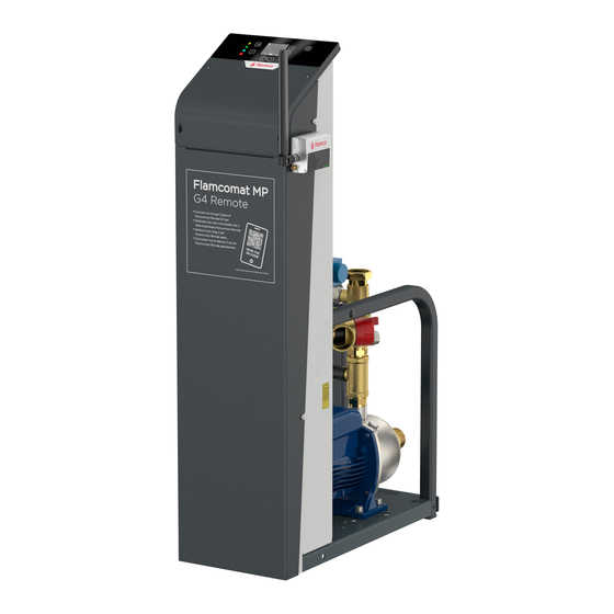
Flamcomat G3 - G4 /
Flexcon M-K/U
> 110° C Safety Set
Installation and operating instructions > 110° Safety Set Flamcomat G3 - G4 and Flexcon
ENG
M-K/U expansion automats for system over 110° C according EN 12953-6 2011.
Montage- und Bedienungsanleitung >110°C Sicherheitsset für Flamcomat G3-G4 und Flexcon
DEU
M-K/U Druckhalteautomaten in Systemen über 110°C nach EN12953-6 2011.
Montage- en gebruikshandleiding > 110° Veiligheid Set Flamcomat G3 - G4 en Flexcon M-K/U
NLD
expansie automaat voor systemen boven 110° C volgens EN 12953-6 2011.
FRA
Instructions de montage et d'utilisation > 110° Safety Set Flamcomat G3 - G4 and Flexcon
M-K/U expansion automats for system over 110° C according EN 12953-6 2011.
Flamcomat G3 - G4:
B
A
C
E
D
F
Flexcon M-K/U
J
I
K
L
D
N
M
H
flamcogroup.com/manuals
G
I
O
O
B
A
D
C
C
D
D
Installation and operating instructions
ENG
ENG
This manual describes how Flamco expansion automats could be used in heating systems where the Boiler
supply line temperature is exceeding 110°C according EN 12953-6 2011 and is therefore applicable for Europe.
This instruction is a supplement to the main Installation and Operating instructions: Flamcomat G3/G4 and
Flexcon M-K/U, see DocFinder www.flamcogroup.com.
Suitable for Flamco controlers
Flextronic:
• The Flextronic controller is plug-and-play ready for >110°C applications.
• Next to the hydraulic layout and sensors on the next pages, there is also a failsafe boiler cut-off output that
must be connected according EN 12953-6 2011.
• [Art.: 17504] Kit with plug-and-play connection piece with Temperature limiter, Minimal pressure limiter and
wiring.
• [Art.: 22386] Membrane rupture sensor is Flamco advised to use together with the >110°C kit.
Settings and terminal connections are mentioned in the Quick Start Guides delivered with our products.
SPC:
• The SPC controller can be used with the same sensors and kit mentioned for the Flextronic, but has no boiler
cut-off signal. In this case the customer has two options:
- Upgrade with a Flextronic retrofit kit.
- Provide a fail save boiler cut-off connected to the general fault terminals of the SPC.
J
Example Boiler cut-off wiring:
The general fault connection (terminals 13-14) will open when there is an error/problem in the heating system or
automat. This is an normaly closed (NC) contact that will also open in case off power loss or broken controller.
K
Minimal faults that must be activated in [MENU 8-4] of the SPC-controller:
1. Pressure (standard setting)
2. Level vessel (standard setting)
3. Diaph. rupture (only when this option is installed)
5. Min. Pressure limiter
6. Temp. monitor
See images on the left for schematic system layout with Flamcomat and Flexcon M-K/U.
Legend
L
A
Auxillary Vessel
B
Main Vessel
C
Membrane rupture Sensor
D
Lockshield Valve with Draining
E
Auxillary vessel flexible Connection
M
F
Flamcomat main Vessel flexible Connection
G
Refill / Top-up line (available with impuls water
N
meter, water filter)
H
Refill / Top-up pump unit (for suppletion under
system pressure)
I
Heat generator
J
Heating system supply line (> 105° C)
K
Heating system return line (< 90° C)
L
Intermediate Vessel Flexcon V-B
M
Minimum pressure Safety Switch
N
Bimetalic temperature Switch
O
Automatic controlled Compressor- / Pump Unit
Excluded:
The wiring cable of the potential free NC fault signal from Flextronic (P29), to cut-off and lock out the heat
supply, is to be provided by user.
Evidence of conversion and release for operation
This must be documented and made available to the owner/operator.
Montage- und Betriebsanleitung
Montage- und Betriebsanleitung
DEU
DEU
Diese Anleitung beschreibt die Möglichkeit des Einsatzes von Flamco Druckhalteautomaten in Heizungssystemen
mit einer maximal zulässigen Heizungsvorlauftemperatur > 110°C gemäß EN12953-62011 für den Einsatz in
Europa.
Das vorliegende Dokument ist eine Ergänzung zur Installations- und Bedienungsanleitung: Flamcomat G3/G4
und Flexcon M-K-/U, siehe DocFinder an www.flamcogroup.com.
Geeignet für Flamco Steuerungen
Flextronic:
• The Flextronic Steuerung ist per Plug and Play für >110°C Einsatz vorbereitet.
• Neben dem hydraulischen Layout und Sensoren auf den nächsten Seiten gibt es auch einen Ausgang zur
Fehler-Sicherheitsabschaltung des Kessels, welcher gemäß EN 12953-6 2011 angeschlossen werden muss.
• [Art.: 17504] Kit mit Plug and Play Anschlussbaugruppe mit Temperaturbegrenzer, Minmaldruckbegrenzer
und Kabelverbindungen
• [Art.: 22386] Membranbruchsensor wird von Flamco in Verbindung mit dem >110°C Kit empfohlen.
Die Einstellungen und Klemmenbelegungen werden in der Schnell Start Anleitung beschrieben, die zum
Lieferumfang des Produktes gehört.
SPC:
• Die SPC-Steuerung können mit den gleichen Sensoren und Kit verwendet werden, wie bei der Flextronic
beschrieben. Allerdings verfügt die SPC nicht über einen Signalausgang zur Kesselabschaltung. Für diesen Fall
gibt es zwei Optionen:
- Umrüstung auf die Flextronic.
- Anschluss der Fehler- Sicherheitsabschaltungen die Sammelstörmeldung der der SPC Steuerung.
Beispiel für die Verdrahtung zur Kesselabschaltung:
Die Sammelstörmeldung (Klemme 13 – 14) öffnet, bei einem Fehler/Problem in der Heizungsanlage oder am
Automaten. Es ist ein NC-Kontakt (normaly closed), der auch bei Unterbrechnung der Stromversorgung oder
Defekt der Steuerung öffnet. Die entsprechenden Fehler müssen in der SPC-Steuerung [Menü 8-4] aktiviert
werden:
1. Druck (Standardeinstellung)
2. Niveau behälter (Standardeinstellung)
3. Membranbruch (nur, wenn diese Option installiert ist)
5. Mindestdruckbegrenzer
EN12953
Flamco
6. Temperaturwächter
Optional
required
recommended
x
Siehe Bilder links als schematische Systemdarstellungen mit Flamcomat und Flexcon M-K/U.
x
x
Legende
x
x
x
x
x
A
Beistellbehälter
x
B
Hauptbehälter
x
C
Membranbruchsensor
(x)
x
D
Kappenventil mit Entleerung
E
Beistellbehälter mit flexibler Anschlussverbindung
x
(x)
F
Flamcomat Hauptbehälter mit flexibler An-
schlussverbindung
x
x
G
Nachspeisestrang (verfügbar mit Impulswasser-
x
x
zähler, Wasserfilter)
x
x
H
Nachspeisung pumengesteuert, (für Anlagen mit
x
x
x
Nachspeisedrücken < Systemdruck)
x
x
x
I
Heizkessel
x
x
x
J
Heizungssystem Vorlauf (> 105° C)
x
x
K
Heizungssystem Rücklauf (< 90° C)
L
Vorlagebehälter Flexcon V-B
M
Minimaldruckbegrenzer
N
Bimetall-Temeperatur-Schalter
O
Automatische Kompressor-/ Pumpendruckhaltung
Nicht enthalten:
Die Kabelverbindung zwischen dem potentialfreien NC-Fehlersignal der Flextronic (P29) und der Verriegelung
des Wärmeerzeugers ist bauseits zu erstellen.
Nachweis der Umbauleistung und Freigabe zum Betrieb.
Sie sind zu dokumentieren und dem Eigentümer/Betreiber vorzulegen.
Anforderung
Flamco
Optional
EN12953
Empfehlung
x
x
x
x
x
x
x
x
x
x
(x)
x
x
(x)
x
x
x
x
x
x
x
x
x
x
x
x
x
x
x
x
x
Publicité

Manuels Connexes pour flamco mat G3


Sommaire des Matières pour flamco mat G3
- Page 1 Montage- und Betriebsanleitung Montage- und Betriebsanleitung This manual describes how Flamco expansion automats could be used in heating systems where the Boiler Diese Anleitung beschreibt die Möglichkeit des Einsatzes von Flamco Druckhalteautomaten in Heizungssystemen supply line temperature is exceeding 110°C according EN 12953-6 2011 and is therefore applicable for Europe.
- Page 2 • [Art.: 22386] Membraanbreuksensor is door Flamco geadviseerd te gebruiken tezamen met de >110°C kit. • [Art. : 22386] Flamco recommande d’utiliser le capteur de rupture de membrane avec le kit > 110 ° C. . M-K/U Druckhalteautomaten in Systemen über 110°C nach EN12953-6 2011.