Table des Matières

Publicité

Les langues disponibles
  • FR

Les langues disponibles

Liens rapides

M2302 gateway user manual
please select the language
English
Français
Italiano
Polski
Español
Português
eština
Sloven ina
Suomi
Norsk
Svenska
Dansk

Publicité

Table des Matières
loading

Sommaire des Matières pour ABB M2302

  • Page 1 M2302 gateway user manual please select the language English Français Italiano Polski Español Português eština Sloven ina Suomi Norsk Svenska Dansk...
  • Page 2 ABB-Welcome M Pos: 2 /DinA4 - Anl eitun gen Online /Inh alt/KNX/Doo rEntry /832 20-AP- xxx/Tit elblat t - 832 20-AP-xxx - ABB @ 1 9\m od_ 132 3249 806 476 _15. docx @ 11 108 4 @ @ 1...
  • Page 3: Table Des Matières

    Pos: 4 /Busc h-Ja ege r (N eust rukt ur)/ Mo dul-St ruktu r/Onli ne-D oku ment ation /Inh altsve rzeich nis ( --> Fü r alle Doku men te <-- )/In haltsve rzeic hnis @ 19\ mod _13 206 490 4438 6_1 5.d ocx @ 109 653 @ @ 1 Safety ....................... 3 Intended use ..................... 3 Environment ....................3 ABB devices ................3 Operation ....................5 Control elements ............... 5 Operating modes ..............6 4.2.1...
  • Page 4: Safety

    Therefore, dispose of the device at the appropriate collecting depot. Pos: 12 /Di nA4 - A nleitu ngen Onlin e/Ueb ersc hrift en/2 ./ABB Gera ete @ 19 \mo d_1 323 162 843 832_ 15. docx @ 11 087 5 @ 2 @ 1 ABB devices Pos: 13 /B usch-J aeg er (Neus truk tur )/M odul -Strukt ur/O nline -Doku me ntatio n/Umw elt ( -->...
  • Page 5 ABB-Welcome M Environment ABB products meet the legal requirements, in particular the laws governing electronic and electrical devices and the REACH ordinance. (EU-Directive 2002/96/EG W EEE and 2002/95/EG RoHS) (EU-REACH ordinance and law for the implementation of the ordinance (EG) No.1907/2006)
  • Page 6: Operation

    ABB-Welcome M Operation Pos: 18 /Di nA4 - A nleitu ngen Onlin e/Ueb ersc hrift en/1 ./Bedie nun g @ 18\m od_ 130 261 392 416 5_15 .docx @ 1 033 65 @ 1 @ 1 Operation Pos: 19 /Di nA4 - A nleitu ngen Onlin e/Ueb ersc hrift en/2 ./Nor male r Bet rieb @ 18 \mo d_1 302 768 8209 65_ 15. docx @ 10 3540 @ 2 @ 1 Control elements Pos: 20 /Di nA4 - A nleitu ngen Onlin e/Ueb ersc hrift en/3 ./Bedie nele men te @ 20\ mod _13 232 6022 055 9_1 5.do cx @ 1 116 47 @ 3 @ 1...
  • Page 7: Operating Modes

    ABB-Welcome M Operation Pos: 26 /Di nA4 - A nleitu ngen Onlin e/Ueb ersc hrift en/2 ./Bedie nakti onen @ 2 0\m od_ 1323 262 294 281 _15. docx @ 11 191 1 @ 2 @ 1 Operating modes Pos: 71 /Di nA4 - A nleitu ngen Onlin e/Ueb ersc hrift en/3 ./Abschl usswide rsta nd @ 19\ mod _13 219 5807 990 6_1 5.do cx @ 1100 83 @ 3 @ 1 Pos: 72 /Di nA4 - A nleitu ngen Onlin e/In halt/KNX/Do orEnt ry/Bedie nun g/Abschl usswide rsta nd s etzen 83 220 -AP-xxx @ 19\ mod _13 1072 339 236 9_1 5.do cx @ 1 078 41 @ @ 1...
  • Page 8 ABB-Welcome M Operation Enable one building as an independent sub-system(-outdoor station(s)/ -guard unit(s) can be connected). Up to 60 such systems are supported within the whole system. The gateway address is equal to the riser number. Fig. 3: Building gateway Wiring diagram: Fig.
  • Page 9: Floor Gateway

    ABB-Welcome M Operation 4.2.2 Floor gateway Fig. 5: Floor gateway Functions 1->OFF, 2->OFF, 3->ON — 8 —...
  • Page 10 ABB-Welcome M Operation Enable a multi-apartment as an independent sub-system(another outdoor station can be connected, for example in front of the door of the floor with the multi-apartment). The gateway address is equal to the minimum address of the indoor station inside the sub-system.
  • Page 11 ABB-Welcome M Operation Wiring diagram: Fig. 7: Floor gateway If using pushbutton outdoor station as a gate station, floor gateway is available for this kind of use case. In following example an outdoor station is mounted at the gate entrance with which all six apartments can be called.
  • Page 12 ABB-Welcome M Operation Apartment 01 A Apartment 02 B Apartment 03 C Apartment 04 D Apartment 04 A Apartment 01 A Apartment 05 B Apartment 05 E Apartment 02 B Apartment 06 C Apartment 06 F Apartment 03 C Outdoor station...
  • Page 13: Apartment Gateway

    ABB-Welcome M Operation 4.2.3 Apartment gateway Fig. 8: Apartment gateway Functions 1->OFF, 2->ON, 3->OFF — 12 —...
  • Page 14 ABB-Welcome M Operation Enable one apartment as an independent sub-system (The 2nd confirmed outdoor station can be connected). Up to 99 such systems can be supported within the whole system. The gateway address is equal to the apartment number. Fig. 9: Apartment gateway —...
  • Page 15 ABB-Welcome M Operation Wiring diagram: Fig. 10: Apartment gateway — 14 —...
  • Page 16: Additional Power Supply Mode

    ABB-Welcome M Operation 4.2.4 Additional power supply mode Fig. 11: Additional power supply mode Functions 1->OFF, 2->ON, 3->ON — 15 —...
  • Page 17 ABB-Welcome M Operation Enable an additional power source for systems with a system controller. ★ Using gateway + system controller as auxiliary power supply to ★ connect to other indoor stations in the same building, when one system controller can’t cover all consmer units.
  • Page 18 ABB-Welcome M Operation Wiring diagram: Fig. 13: Additional power supply mode — 17 —...
  • Page 19: Line Amplifier

    ABB-Welcome M Operation 4.2.5 Line amplifier Fig. 14: Line amplifier Functions 1->ON, 2->OFF, 3->OFF Strengthen the video signal and extend transmission. The increased distance please refer to ABB-W elcome M system manual. Fig. 15: Line amplifier — 18 —...
  • Page 20 ABB-Welcome M Operation Wiring diagram: Fig. 16: Line amplifier Pos: 75 /B usch-J aeg er (Neus truk tur )/M odul -Strukt ur/O nline -Doku me ntatio n/Steu er mod ule - Onlin e-Dok ume ntati on ( -- > F ür alle Dok ume nte <- -)/ +++ ++ ++ +++ ++ S eiten umb ruch + +++ ++ ++ +++ + @ 9\m od_ 126 8898 668 093 _0. docx @ 521 49 @ @ 1...
  • Page 21: Technical Data

    ABB-Welcome M Technical data Pos: 76 /Di nA4 - A nleitu ngen Onlin e/Ueb ersc hrift en/1 ./T echnisc he D aten @ 18 \mo d_1 302 615 863 001 _15. docx @ 10 341 6 @ 1 @ 1 Technical data Pos: 77 /Di nA4 - A nleitu ngen Onlin e/In halt/KNX/Do orEnt ry/83 220 -AP-xxx/ Tech nische Date n - 832 20-AP-x xx @ 1 8\m od_ 130 321 285 4559 _15 .docx @ 1 037 05 @ @ 1...
  • Page 22: Mounting / Installation

    ABB-Welcome M Mounting / Installation Pos: 79 /B usch-J aeg er (Neus truk tur )/M odul -Strukt ur/O nline -Doku me ntatio n/Übe rsch rifte n ( --> Fü r alle Doku men te < -- )/1. E bene /M - O/ Mont age / Ins tallatio n @ 18\ mod _13 0261 396 611 1_1 5.do cx @ 1 033 73 @ 1 @ 1 Mounting / Installation Pos: 80 /B usch-J aeg er (Neus truk tur )/M odul -Strukt ur/O nline -Doku me ntatio n/Siche rheit (- ->...
  • Page 23: General Installation Instructions

    Pos: 85. 1 /DinA4 - Anleit ung en O nline/I nhal t/KNX/DoorE ntry/ 832 20-AP-xxx /Mo nta ge - Mo dule/ Mon tag e - Mon tage dos e -- 83 220 -AP-xxx @ 19\ mod _132 325 040 684 8_1 5.doc x @ 1 110 98 @ @ 1 The device M2302 must only be installed on mounting rails according to DIN EN 500022.
  • Page 24 W e reserve the right to at all times make technical changes as well as changes to the contents of this document without prior notice. The detailed specifications agreed to at the time of ordering apply to all orders. ABB accepts no responsibility for possible errors or incompleteness in this document.
  • Page 25 ABB-Welcome M Pos: 2 /DinA4 - Anl eitun gen Online /Inh alt/KNX/Doo rEntry /832 20-AP- xxx/Tit elblat t - 832 20-AP-xxx - ABB @ 1 9\m od_ 132 3249 806 476 _15. docx @ 11 108 4 @ @ 1...
  • Page 26 Pos: 4 /Busc h-Ja ege r (N eust rukt ur)/ Mo dul-St ruktu r/Onli ne-D oku ment ation /Inh altsve rzeich nis ( --> Fü r alle Doku men te <-- )/In haltsve rzeic hnis @ 19\ mod _13 206 490 4438 6_1 5.d ocx @ 109 653 @ @ 1 Sécurité ....................3 Usage prévu ..................... 3 Environnement ..................3 Appareils ABB ................4 Fonctionnement ..................5 Éléments de commande ............5 Modes de fonctionnement ............7 4.2.1...
  • Page 27: Sécurité

    Par conséquent, l'élimination de l'appareil doit se faire dans un centre de collecte approprié. Pos: 12 /Di nA4 - A nleitu ngen Onlin e/Ueb ersc hrift en/2 ./ABB Gera ete @ 19 \mo d_1 323 162 843 832_ 15. docx @ 11 087 5 @ 2 @ 1...
  • Page 28: Appareils Abb

    Pos: 13 /B usch-J aeg er (Neus truk tur )/M odul -Strukt ur/O nline -Doku me ntatio n/Umw elt ( --> F ür all e Doku me nte <-- )/Hinweis e/Hinw eis - U mwelt - ABB Elektro ger äte...
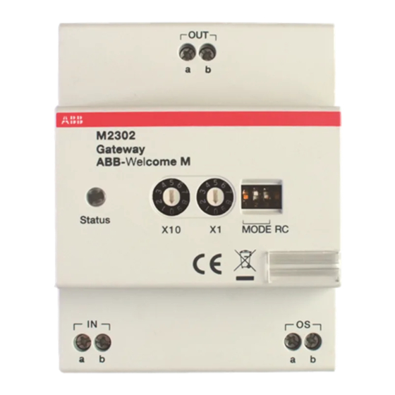
  • Page 29: Fonctionnement

    ABB-Welcome M WM0805 Pos: 18 /Di nA4 - A nleitu ngen Onlin e/Ueb ersc hrift en/1 ./Bedie nun g @ 18\m od_ 130 261 392 416 5_15 .docx @ 1 033 65 @ 1 @ 1 Fonctionnement Pos: 19 /Di nA4 - A nleitu ngen Onlin e/Ueb ersc hrift en/2 ./Nor male r Bet rieb @ 18 \mo d_1 302 768 8209 65_ 15. docx @ 10 3540 @ 2 @ 1 Éléments de commande...
  • Page 30 ABB-Welcome M WM0805 N° Fonctions Bus entrée/sortie Réglages des modes de fonctionnem ent : Pour plus de détails, voir Chapitre « Modes de fonctionnement » Résistance terminale ON / OFF Dans les installations vidéo ou les installations audio/vidéo combinées, le commutateur doit être défini comme «...
  • Page 31: Modes De Fonctionnement

    ABB-Welcome M WM0805 Pos: 26 /Di nA4 - A nleitu ngen Onlin e/Ueb ersc hrift en/2 ./Bedie nakti onen @ 2 0\m od_ 1323 262 294 281 _15. docx @ 11 191 1 @ 2 @ 1 Modes de fonctionnement Pos: 71 /Di nA4 - A nleitu ngen Onlin e/Ueb ersc hrift en/3 ./Abschl usswide rsta nd @ 19\ mod _13 219 5807 990 6_1 5.do cx @ 1100 83 @ 3 @ 1...
  • Page 32 ABB-Welcome M WM0805 Activation d'un bâtiment comme sous-système indépendant (la ou les platine(s) de rue/interface(s) gardien peuvent être connectées). Jusqu'à 60 bâtiments sont pris en charge dans l'ensemble du système. L'adresse de la passerelle est identique au numéro de colonne montante.
  • Page 33 ABB-Welcome M WM0805 Schéma de câblage : Fig. 4 : Passerelle de bâtiment...
  • Page 34: Passerelle D'étage

    ABB-Welcome M WM0805 4.2.2 Passerelle d'étage Fig. 5 : Passerelle d'étage N° Fonctions 1->OFF, 2->OFF, 3->ON...
  • Page 35 ABB-Welcome M WM0805 Activation d'un immeuble à plusieurs appartements comme sous-système indépendant (une autre platine de rue peut être connectée, par exemple devant la porte avec l'immeuble à plusieurs appartements). L'adresse de la passerelle est identique à l'adresse minimum du moniteur intérieur à l'intérieur du sous système.
  • Page 36 ABB-Welcome M WM0805 Schéma de câblage : Fig. 7 : Passerelle d'étage Si une platine de rue avec appel par boutons-poussoirs est utilisée comme platine de rue au portail, la passerelle d'étage conviendra à cette utilisation. Dans l'exemple suivant, une platine de rue est montée à l'entrée du portail et les six appartements peuvent être appelés à...
  • Page 37 ABB-Welcome M WM0805 A l'aide de la passerelle d'étage pour chaque bâtiment, la platine de rue 1 peut gérer ces deux bâtiments, tandis que la platine de rue 2 gère le bâtiment gauche et la platine de rue 3 gère celui de droite.
  • Page 38 ABB-Welcome M WM0805 Schéma de câblage (à l'aide de la passerelle d'étage pour chaque bâtiment) : ST. X100 X10 X1 ST. X100 X10 X1 ST. X100 X10 X1 Adresse Adresse Adresse ST. X100 X10 X1 ST. X100 X10 X1 ST. X100 X10 X1...
  • Page 39: Passerelle D'appartement

    ABB-Welcome M WM0805 4.2.3 Passerelle d'appartement Fig. 8 : Passerelle d'appartement N° Fonctions 1->OFF, 2->ON, 3->OFF...
  • Page 40 ABB-Welcome M WM0805 Activation d'un appartement comme sous-système indépendant. Jusqu'à 99 sous-ensembles peuvent être pris en charge par le système. L'adresse de la passerelle est identique au numéro d'appartement. Fig. 9 : Passerelle d'appartement...
  • Page 41 ABB-Welcome M WM0805 Schéma de câblage : Fig. 10 : Passerelle d'appartement...
  • Page 42: Mode Alimentation Auxiliaire

    ABB-Welcome M WM0805 4.2.4 Mode alimentation auxiliaire Fig. 11 : Mode alimentation auxiliaire N° Fonctions 1->OFF, 2->ON, 3->ON...
  • Page 43 ABB-Welcome M WM0805 Activation d'une source d'alimentation supplémentaire avec une unité centrale. Utilisation de la passerelle et d’une unité ★ centrale comme alimentation auxiliaire pour se connecter ★ aux autres postes intérieurs dans le même bâtiment, lorsqu'une seule unité centrale ne...
  • Page 44 ABB-Welcome M WM0805 Schéma de câblage : Fig. 13 : Mode alimentation supplémentaire...
  • Page 45: Amplificateur De Ligne

    ABB-Welcome M WM0805 4.2.5 Amplificateur de ligne Fig. 14 : Amplificateur de ligne N° Fonctions 1->ON, 2->OFF, 3->OFF...
  • Page 46 ABB-Welcome M WM0805 Amplification du signal vidéo et extension de la transmission. Pour une plus grande distance, voir le manuel du système ABB-Welcome M. Fig. 15 : Amplificateur de ligne...
  • Page 47 ABB-Welcome M WM0805 Schéma de câblage : Fig. 16 : Amplificateur de ligne Pos: 75 /B usch-J aeg er (Neus truk tur )/M odul -Strukt ur/O nline -Doku me ntatio n/Steu er mod ule - Onlin e-Dok ume ntati on ( -- > F ür alle Dok ume nte <- -)/ +++ ++ ++ +++ ++ S eiten umb ruch + +++ ++ ++ +++ + @ 9\m od_ 126 8898 668 093 _0. docx @ 521 49 @ @ 1...
  • Page 48: Caractéristiques Techniques

    ABB-Welcome M WM0805 Pos: 76 /Di nA4 - A nleitu ngen Onlin e/Ueb ersc hrift en/1 ./T echnisc he D aten @ 18 \mo d_1 302 615 863 001 _15. docx @ 10 341 6 @ 1 @ 1 Caractéristiques techniques Pos: 77 /Di nA4 - A nleitu ngen Onlin e/In halt/KNX/Do orEnt ry/83 220 -AP-xxx/ Tech nische Date n - 832 20-AP-x xx @ 1 8\m od_ 130 321 285 4559 _15 .docx @ 1 037 05 @ @ 1...
  • Page 49: Montage / Installation

    ABB-Welcome M WM0805 Pos: 79 /B usch-J aeg er (Neus truk tur )/M odul -Strukt ur/O nline -Doku me ntatio n/Übe rsch rifte n ( --> Fü r alle Doku men te < -- )/1. E bene /M - O/ Mont age / Ins tallatio n @ 18\ mod _13 0261 396 611 1_1 5.do cx @ 1 033 73 @ 1 @ 1 Montage / Installation Pos: 80 /B usch-J aeg er (Neus truk tur )/M odul -Strukt ur/O nline -Doku me ntatio n/Siche rheit (- ->...
  • Page 50: Exigences À L'égard De L'électricien

    ABB-Welcome M WM0805 Exigences à l'égard de l'électricien Avertissement Tension électrique ! L'installation de l'appareil par un électricien est uniquement possible s'il possède les connaissances techniques et compétences nécessaires. • Toute installation incorrecte peut mettre en danger votre vie et celle de l'utilisateur du système électrique.
  • Page 51: Consignes D'installation Générales

    ABB-Welcome M WM0805 Consignes d'installation générales • Terminer toutes les extrémités du système de câblage via un appareil de bus connecté (p. ex., moniteur intérieur, platine de rue, appareil système). • Ne pas installer le contrôleur système juste à côté du transformateur de sonnerie et autres alimentations électriques (pour éviter les interférences).
  • Page 52 Les spécifications détaillées convenues au moment de la commande s'appliquent à toutes les commandes. ABB ne peut être tenu responsable des erreurs ou omissions dans ce document. Nous nous réservons tous les droits de propriété sur ce document, ainsi que sur les informations et les illustrations qu'il contient.
  • Page 53 Sistemi di videocitofonia │ Welcome M │ Manuale utente Welcome M ABB   Pos: 2 /DinA4 - Anleitungen Online/Inhalt/KNX/DoorEntry/83220-AP-xxx/Titelblatt - 83220-AP-xxx - ABB @ 19\mod_1323249806476_15.docx @ 111084 @ @ 1 M2302  Gateway    === Ende der Liste für Textmarke Cover ===...
  • Page 54   Sicurezza ....................... 3       Uso previsto....................3   Ambiente ....................... 3       Dispositivi ABB ................4   Funzionamento ....................5     Comandi ..................5       Modalità di funzionamento ............6 4.2.1  ...
  • Page 55: Sicurezza

    Pos: 9 /DinA4 - Anleitungen Online/Inhalt/KNX/DoorEntry/83220-AP-xxx/Bestimmungsgemaesser Gebrauch - 83220-AP-xxx-500 @ 20\mod_1324561168699_15.docx @ 112728 @ @ 1 Il gateway M2302 è parte integrante del sistema di videocitofonia Welcome M di ABB e funziona unicamente con i componenti di questo sistema. Il dispositivo deve essere installato su guide di montaggio, in conformità...
  • Page 56: Dispositivi Abb

    Dispositivi ABB Pos: 13 /Busch-Jaeger (Neustruktur)/Modul-Struktur/Online-Dokumentation/Umwelt (--> Für alle Dokumente <--)/Hinweise/Hinweis - Umwelt - ABB Elektrogeräte @ 19\mod_1323162745839_15.docx @ 110867 @ @ 1 Tutti gli imballaggi e i dispositivi ABB riportano i marchi e i sigilli di verifica per il corretto smaltimento.
  • Page 57: Funzionamento

          ABB-Welcome M   Pos: 18 /DinA4 - Anleitungen Online/Ueberschriften/1./Bedienung @ 18\mod_1302613924165_15.docx @ 103365 @ 1 @ 1 Funzionamento Pos: 19 /DinA4 - Anleitungen Online/Ueberschriften/2./Normaler Betrieb @ 18\mod_1302768820965_15.docx @ 103540 @ 2 @ 1 Comandi Pos: 20 /DinA4 - Anleitungen Online/Ueberschriften/3./Bedienelemente @ 20\mod_1323260220559_15.docx @ 111647 @ 3 @ 1 Pos: 21 /DinA4 - Anleitungen Online/Inhalt/KNX/DoorEntry/83220-AP-xxx/Bedienelemente - 83220-AP-xxx @ 18\mod_1303212853605_15.docx @ 103673 @ @ 1...
  • Page 58: Modalità Di Funzionamento

          ABB-Welcome M   Pos: 26 /DinA4 - Anleitungen Online/Ueberschriften/2./Bedienaktionen @ 20\mod_1323262294281_15.docx @ 111911 @ 2 @ 1 Modalità di funzionamento Pos: 71 /DinA4 - Anleitungen Online/Ueberschriften/3./Abschlusswiderstand @ 19\mod_1321958079906_15.docx @ 110083 @ 3 @ 1 Pos: 72 /DinA4 - Anleitungen Online/Inhalt/KNX/DoorEntry/Bedienung/Abschlusswiderstand setzen 83220-AP-xxx @ 19\mod_1310723392369_15.docx @ 107841 @ @ 1 4.2.1...
  • Page 59: Gateway Dell'edificio

          ABB-Welcome M   Abilita un edificio come sottosistema indipendente (possibilità di collegamento di una portineria/posto esterno). L'intero sistema supporta fino a 60 edifici secondari. L'indirizzo di gateway corrisponde al numero della montante.   Fig. 3:  Gateway dell'edificio     ...
  • Page 60       ABB-Welcome M   Schema elettrico:      Fig. 4:  Gateway modalità edificio    Importante: l’utilizzo del gateway in modalità edificio necessità del posto esterno principale  alfanumerico per permettere l’indirizzo corretto degli interni.  Non è disponibile la funzionalità di intercomunicante tra diversi edifici        |   — 8 —...
  • Page 61: Gateway Di Piano

          ABB-Welcome M   4.2.2 Gateway di piano     Fig. 5:  Gateway di piano    N° Funzioni 1->OFF, 2->OFF, 3->OFF       |   — 9 —...
  • Page 62       ABB-Welcome M   Abilita un sottosistema indipendente di multi-appartamenti (è possibile collegare un altro posto esterno, ad esempio di fronte alla porta del piano). L'indirizzo di gateway corrisponde all’indirizzo del primp  posto interno nel sottosistema gestito.   Fig. 6:  Gateway di piano          |   — 10 —...
  • Page 63       ABB-Welcome M   Schema elettrico:      Fig. 7:  Gateway di piano    Se il  posto esterno è usato come gate station, è possibile utilizzare anche il gateway di piano.  L'esempio che segue mostra un posto esterno installato all'ingresso principale con cui è possibile  chiamare tutti e sei gli appartamenti. Un posto esterno si trova nell'edificio di sinistra con gli  appartamenti da 01 a 03 e un altro posto esterno si trova nell'edificio di destra con gli appartamenti da  04 a 06.   Utilizzando il gateway di piano per ogni edificio, il posto esterno 1 gestisce questi due edifici, mentre il  posto esterno 2 gestisce l'edificio di sinistra e il posto esterno 3 gestisce l'edificio di destra.        |   — 11 —...
  • Page 64       ABB-Welcome M   Appartamento 01 A Appartamento 02 B Appartamento 03 C Appartamento Appartamento Appartamento 04 A 04 D 01 A Appartamento Appartamento Appartamento 05 B 05 E 02 B Appartamento Appartamento Appartamento 06 F 06 C...
  • Page 65: Gateway Di Appartamento

          ABB-Welcome M   4.2.3 Gateway di appartamento     Fig. 8:  Gateway di appartamento    N° Funzioni 1->OFF, 2->ON, 3->OFF       |   — 13 —...
  • Page 66       ABB-Welcome M   Abilita un appartamento come sottosistema indipendente (possibilità di collegamento di un posto esterno a singola chiamata ). L'intero sistema è in grado di supportare fino a 99 sotto- sistemi. L'indirizzo di gateway corrisponde al numero dell'appartamento.
  • Page 67       ABB-Welcome M   Schema elettrico:   Fig. 10:  Gateway di appartamento        |   — 15 —...
  • Page 68: Modalità Di Alimentazione Supplementare

          ABB-Welcome M   4.2.4 Modalità di alimentazione supplementare     Fig. 11:  Modalità di alimentazione supplementare    N° Funzioni 1->OFF, 2->ON, 3->ON       |   — 16 —...
  • Page 69       ABB-Welcome M   Permette di interfacciare un alimentatore supplementare in un sistema. ★ Gateway + centrale di sistema come alimentazione ausiliaria per il ★ collegamento ad altri posti interni all'interno dello stesso edificio, nei casi in cui...
  • Page 70       ABB-Welcome M   Schema elettrico:      Fig. 13:  Modalità di alimentazione supplementare        |   — 18 —...
  • Page 71: Amplificatore Di Linea

          ABB-Welcome M   4.2.5 Amplificatore di linea     Fig. 14:  Amplificatore di linea    N° Funzioni 1->ON, 2->OFF, 3->OFF         |   — 19 —...
  • Page 72       ABB-Welcome M   Permette di rafforzare il segnale video ed estendere le distanze. Per distanze maggiori fare riferimento al manuale di sistema Welcome M ABB.   Fig. 15:  Amplificatore di linea        |   — 20 —...
  • Page 73       ABB-Welcome M   Schema elettrico:      Fig. 16:  Amplificatore di linea  Pos: 75 /Busch-Jaeger (Neustruktur)/Modul-Struktur/Online-Dokumentation/Steuermodule - Online-Dokumentation (--> Für alle Dokumente <--)/++++++++++++ Seitenumbruch ++++++++++++ @ 9\mod_1268898668093_0.docx @ 52149 @ @ 1       |   — 21 —...
  • Page 74: Dati Tecnici

          ABB-Welcome M   Pos: 76 /DinA4 - Anleitungen Online/Ueberschriften/1./Technische Daten @ 18\mod_1302615863001_15.docx @ 103416 @ 1 @ 1 Dati tecnici Pos: 77 /DinA4 - Anleitungen Online/Inhalt/KNX/DoorEntry/83220-AP-xxx/Technische Daten - 83220-AP-xxx @ 18\mod_1303212854559_15.docx @ 103705 @ @ 1 Denominazione...
  • Page 75: Montaggio/Installazione

          ABB-Welcome M   Pos: 79 /Busch-Jaeger (Neustruktur)/Modul-Struktur/Online-Dokumentation/Überschriften (--> Für alle Dokumente <--)/1. Ebene/M - O/Montage / Installation @ 18\mod_1302613966111_15.docx @ 103373 @ 1 @ 1 Montaggio/Installazione Pos: 80 /Busch-Jaeger (Neustruktur)/Modul-Struktur/Online-Dokumentation/Sicherheit (--> Für alle Dokumente <--)/Warnhinweise/Sicherheit - Niederspannungs- und 230 V-Leitungen @ 18\mod_1302617821491_15.docx @ 103465 @ @ 1 Attenzione ...
  • Page 76: Istruzioni Generali Di Installazione

          ABB-Welcome M   Tensione elettrica! L'installazione del dispositivo può essere effettuata solo se si dispone delle necessarie competenze ed esperienze in campo elettrico. • Un'installazione non corretta mette a rischio la vostra vita e quella dell'utente dell'impianto elettrico.
  • Page 77: Montaggio

    Montaggio Pos: 85.1 /DinA4 - Anleitungen Online/Inhalt/KNX/DoorEntry/83220-AP-xxx/Montage - Module/Montage - Montagedose -- 83220-AP-xxx @ 19\mod_1323250406848_15.docx @ 111098 @ @ 1 Il dispositivo M2302 deve essere installato su guide di montaggio, in conformità alla norma DIN EN 500022. Pos: 83 /Busch-Jaeger (Neustruktur)/Modul-Struktur/Online-Dokumentation/Steuermodule - Online-Dokumentation (--> Für alle Dokumente <--)/++++++++++++ Seitenumbruch ++++++++++++ @ 9\mod_1268898668093_0.docx @ 52149 @ @ 1  ...
  • Page 78 Ci riserviamo il diritto di apportare, in qualsiasi momento, modifiche tecniche o modificare il contenuto del presente documento senza preavviso. Le specifiche dettagliate concordate al momento dell'ordine si applicano a tutti gli ordini. ABB declina ogni responsabilità per eventuali errori o incompletezze in questo documento.
  • Page 79 Urządzenie ABB-Welcome M Pos: 2 /DinA4 - Anl eitun gen Online /Inh alt/KNX/Doo rEntry /832 20-AP- xxx/Tit elblat t - 832 20-AP-xxx - ABB @ 1 9\m od_ 132 3249 806 476 _15. docx @ 11 108 4 @ @ 1...
  • Page 80 Pos: 4 /Busc h-Ja ege r (N eust rukt ur)/ Mo dul-St ruktu r/Onli ne-D oku ment ation /Inh altsve rzeich nis ( --> Fü r alle Doku men te <-- )/In haltsve rzeic hnis @ 19\ mod _13 206 490 4438 6_1 5.d ocx @ 109 653 @ @ 1 Bezpieczeństwo ..................3 Przeznaczenie ..................3 Środowisko ....................3 Urządzenia ABB ................ 3 Działanie ....................5 Elementy sterujące ..............5 Tryby pracy ................6 4.2.1...
  • Page 81: Bezpieczeństwo

    Dlatego należy je oddać do odpowiedniego punktu zbiórki. Pos: 12 /Di nA4 - A nleitu ngen Onlin e/Ueb ersc hrift en/2 ./ABB Gera ete @ 19 \mo d_1 323 162 843 832_ 15. docx @ 11 087 5 @ 2 @ 1 Urządzenia ABB Pos: 13 /B usch-J aeg er (Neus truk tur )/M odul -Strukt ur/O nline -Doku me ntatio n/Umw elt ( -->...
  • Page 82 ABB-Welcome Produkty firmy ABB spełniają wymogi prawne i są w szczególności zgodne z ustawami o urządzeniach elektrycznych i elektronicznych oraz rozporządzeniem REACH. (Dyrektywa UE 2002/96/EG W EEE i RoHS 2002/95/W E) (Rozporządzenie UE REACH i ustawa wykonawcza do rozporządzenia (W E) nr 1907/2006) —...
  • Page 83: Działanie

    ABB-Welcome Pos: 18 /Di nA4 - A nleitu ngen Onlin e/Ueb ersc hrift en/1 ./Bedie nun g @ 18\m od_ 130 261 392 416 5_15 .docx @ 1 033 65 @ 1 @ 1 Działanie Pos: 19 /Di nA4 - A nleitu ngen Onlin e/Ueb ersc hrift en/2 ./Nor male r Bet rieb @ 18 \mo d_1 302 768 8209 65_ 15. docx @ 10 3540 @ 2 @ 1 Elementy sterujące...
  • Page 84: Tryby Pracy

    ABB-Welcome Pos: 26 /Di nA4 - A nleitu ngen Onlin e/Ueb ersc hrift en/2 ./Bedie nakti onen @ 2 0\m od_ 1323 262 294 281 _15. docx @ 11 191 1 @ 2 @ 1 Tryby pracy Pos: 71 /Di nA4 - A nleitu ngen Onlin e/Ueb ersc hrift en/3 ./Abschl usswide rsta nd @ 19\ mod _13 219 5807 990 6_1 5.do cx @ 1100 83 @ 3 @ 1 Pos: 72 /Di nA4 - A nleitu ngen Onlin e/In halt/KNX/Do orEnt ry/Bedie nun g/Abschl usswide rsta nd s etzen 83 220 -AP-xxx @ 19\ mod _13 1072 339 236 9_1 5.do cx @ 1 078 41 @ @ 1...
  • Page 85 ABB-Welcome Pojedynczy budynek może być teraz niezależnym podsystemem (można podłączyć stację zewnętrzną/konsolę portierską). Obsługuje nawet 60 systemów w ramach całego systemu. Adres bramy jest równoznaczny z numerem pionu. Rys. 3 Brama budynku — 7 —...
  • Page 86 ABB-Welcome Schemat okablowania: Rys. 4 Brama budynku — 8 —...
  • Page 87: Brama Piętra

    ABB-Welcome 4.2.2 Brama piętra Rys. 5 Brama piętra Funkcje 1->W YŁ., 2->WYŁ., 3->W Ł. — 9 —...
  • Page 88 ABB-Welcome Dzięki niej kilka mieszkań może stać się niezależnym podsystemem (można podłączyć dodatkową stację zewnętrzną na przykład przed drzwiami na piętro, na którym znajduje się kilka mieszkań). Adres bramy jest równoznaczny z minimalnym adresem stacji wewnętrznej wewnątrz podsystemu. Rys. 6 Brama piętra...
  • Page 89 ABB-Welcome Schemat okablowania: Rys. 7 Brama piętra Jeśli stacja zewnętrzna z przyciskami używana jest jako stacja bramy, do tego typu zastosowań można również wykorzystać bramę piętra. W takim przypadku stacja zewnętrzna jest montowana przy bramie wejściowej, z której można się połączyć ze wszystkimi sześcioma mieszkaniami. Jedna stacja zewnętrzna znajduje się...
  • Page 90 Apartment 01 A Apartment 02 B Apartment 02 B Apartment 03 C Apartment 03 C Apartment 04 D Apartment 04 A Apartment 05 E Apartment 05 B Apartment 06 F Apartment 06 C M2302 M2302 X10 X1 X10 X1 — 12 —...
  • Page 91: Brama Mieszkania

    ABB-Welcome 4.2.3 Brama mieszkania Rys. 8 Brama mieszkania Funkcje 1->W YŁ., 2->WŁ., 3->WYŁ. — 13 —...
  • Page 92 ABB-Welcome Ustawienie pojedynczego mieszkania jako niezależnego podsystemu (można podłączyć drugą potwierdzoną stację zewnętrzną). Cały system obsługuje do 99 takich systemów. Adres bramy jest równoznaczny z numerem mieszkania. Rys. 9 Brama mieszkania — 14 —...
  • Page 93 ABB-Welcome Schemat okablowania: Rys. 10 Brama mieszkania — 15 —...
  • Page 94: Tryb Dodatkowego Zasilania Elektrycznego

    ABB-Welcome 4.2.4 Tryb dodatkowego zasilania elektrycznego Rys. 11 Tryb dodatkowego zasilania elektrycznego Funkcje 1->W YŁ., 2->WŁ., 3->WŁ. — 16 —...
  • Page 95 ABB-Welcome Stanowi dodatkowe źródło zasilania systemu ze sterownikiem systemu. ★ Wykorzystanie bramy i sterownika systemu jako dodatkowego ★ zasilania elektrycznego dla innych stacji wewnętrznych w tym samym budynku, jeśli pojedynczy sterownik systemu nie ★ Rys. 12 Tryb dodatkowego zasilania elektrycznego...
  • Page 96 ABB-Welcome Schemat okablowania: Rys. 13 Tryb dodatkowego zasilania elektrycznego — 18 —...
  • Page 97: Wzmacniacz Linii

    4.2.5 Wzmacniacz linii Rys. 14 Wzmacniacz linii Funkcje 1->W Ł., 2->WYŁ., 3->WYŁ. Wzmocnienie sygnału wideo i rozszerzenie transmisji. Więcej informacji na temat rozszerzania transmisji można znaleźć w instrukcji obsługi systemu ABB- Welcome M. Rys. 15 Wzmacniacz linii — 19 —...
  • Page 98 ABB-Welcome Schemat okablowania: Rys. 16 Wzmacniacz linii Pos: 75 /B usch-J aeg er (Neus truk tur )/M odul -Strukt ur/O nline -Doku me ntatio n/Steu er mod ule - Onlin e-Dok ume ntati on ( -- > F ür alle Dok ume nte <- -)/ +++ ++ ++ +++ ++ S eiten umb ruch + +++ ++ ++ +++ + @ 9\m od_ 126 8898 668 093 _0. docx @ 521 49 @ @ 1...
  • Page 99: Dane Techniczne

    ABB-Welcome Pos: 76 /Di nA4 - A nleitu ngen Onlin e/Ueb ersc hrift en/1 ./T echnisc he D aten @ 18 \mo d_1 302 615 863 001 _15. docx @ 10 341 6 @ 1 @ 1 Dane techniczne Pos: 77 /Di nA4 - A nleitu ngen Onlin e/In halt/KNX/Do orEnt ry/83 220 -AP-xxx/ Tech nische Date n - 832 20-AP-x xx @ 1 8\m od_ 130 321 285 4559 _15 .docx @ 1 037 05 @ @ 1 Opis Wartość...
  • Page 100: Montaż / Instalacja

    ABB-Welcome Pos: 79 /B usch-J aeg er (Neus truk tur )/M odul -Strukt ur/O nline -Doku me ntatio n/Übe rsch rifte n ( --> Fü r alle Doku men te < -- )/1. E bene /M - O/ Mont age / Ins tallatio n @ 18\ mod _13 0261 396 611 1_1 5.do cx @ 1 033 73 @ 1 @ 1 Montaż...
  • Page 101: Ogólna Instrukcja Montażu

    Pos: 85. 1 /DinA4 - Anleit ung en O nline/I nhal t/KNX/DoorE ntry/ 832 20-AP-xxx /Mo nta ge - Mo dule/ Mon tag e - Mon tage dos e -- 83 220 -AP-xxx @ 19\ mod _132 325 040 684 8_1 5.doc x @ 1 110 98 @ @ 1 Urządzenie M2302 zamontować na szynach montażowych zgodnie z normą DIN EN 500022.
  • Page 102 ABB-Welcome Pos: 83 /B usch-J aeg er (Neus truk tur )/M odul -Strukt ur/O nline -Doku me ntatio n/Steu er mod ule - Onlin e-Dok ume ntati on ( -- > F ür alle Dok ume nte <- -)/ +++ ++ ++ +++ ++ S eiten umb ruch + +++ ++ ++ +++ + @ 9\m od_ 126 8898 668 093 _0. docx @ 521 49 @ @ 1...
  • Page 103 Szczegółowe dane techniczne uzgodnione w czasie składania zamówienia stosuje się do wszystkich zamówień. Firma ABB nie ponosi żadnej odpowiedzialności za błędy ani za braki, jakie mogą pojawić się w niniejszym dokumencie.
  • Page 104: Návod Na Instalaci

    Pos : 2 /Di nA4 - Anleitung en Online/Inhalt/KN X/D oorEntr y/83220- AP- xxx/Titelbl att - 83220-AP- xxx - ABB @ 19\mod_1323249806476_15.doc x @ 111084 @ @ 1 === Ende der Liste für T extmar ke Cover === ABB s.r.o., Elektro-Praga Welcome Midi Gateway systémová, řadová...
  • Page 105 Pos :Pos: 4 /Busc h-J aeg er (Neustr uktur)/Modul- Struktur /Online-Dokumentati on/Inhalts verz eichnis (--> F ür all e D okumente <--)/Inhalts verzeic hnis @ 19\mod_1320649044386_15.doc x @ 109653 @ @ 1 Bezpečnost ....................3 Zamýšlené použití přístroje................3 Ochrana životního prostředí ................3 Zařízení ABB ................3 Provoz ......................4 Ovládací prvky ................4 Provozní režimy ................5 Brána pro budovu .................
  • Page 106: Bezpečnost

    Zařízení ABB Pos : 13 /Busc h-J aeg er (Neustr uktur)/Modul- Struktur /Online-Dokumentati on/U mwel t (--> Für alle D okumente <--)/Hinweis e/Hi nweis - U mwelt - ABB El ektr ogeräte @ 19\mod_1323162745839_15.doc x @ 110867 @ @ 1 Všechny obalové...
  • Page 107: Provoz

    ABB-Welcome Midi Pos : 18 /DinA4 - Anl eitungen Onli ne/Ueberschriften/1./Bedi enung @ 18\mod_1302613924165_15.doc x @ 103365 @ 1 @ 1 Provoz Pos : 19 /DinA4 - Anl eitungen Onli ne/Ueberschriften/2./Nor maler Betrieb @ 18\mod_1302768820965_15.doc x @ 103540 @ 2 @ 1 Ovládací...
  • Page 108: Provozní Režimy

    ABB-Welcome Midi Pos : 26 /DinA4 - Anl eitungen Onli ne/Ueberschriften/2./Bedi enaktionen @ 20 \mod_1323262294281_15.doc x @ 111911 @ 2 @ 1 Provozní režimy Pos : 71 /DinA4 - Anl eitungen Onli ne/Ueberschriften/3./Absc hlus s widerstand @ 19\mod_1321958079906_15.doc x @ 110083 @ 3 @ 1 Pos : 72 /DinA4 - Anl eitungen Onli ne/Inhalt/KN X/D oor Entr y/Bedienung/Absc hl uss widerstand setzen 83220-AP- xxx @ 19\mod_1310723392369_15.doc x @ 107841 @ @ 1...
  • Page 109 ABB-Welcome Midi Umožňuje, aby jedna budova figurovala jako nezávislý podsystém (lze připojit vnější stanice nebo hlíd ací jednotky). V celém systému může být až 60 podobných systémů. Adresa brány je stejná jako číslo stoupacího vedení. Obr. 3. Brána pro budovu Schéma zapojení:...
  • Page 110: Brána Pro Podlaží A Pro Společný Vchod

    ABB-Welcome Midi Brána pro podlaží a pro společný vchod 4.2.2 Obr. 5. Brána pro podlaží Číslo Funkce 1->VYP, 2->VYP, 3->ZAP — 7 —...
  • Page 111 ABB-Welcome Midi Umožňuje, aby více bytů dohromady figurovalo jako nezávislý podsystém (lze připojit další vnější stanici, například před dveř e na podlaží s více byty). Adresa brány je stejná jako nejnižší adresa vnitřní stanice uvnitř podsystému. Obr. 6. Brána pro podlaží...
  • Page 112 ABB-Welcome Midi Jestliže se u hlavního vchodu používá vnější stanice s tlačítky, lze pro tento případ použít bránu pro podlaží. V následujícím příkladu se u hlavního vchodu nainstaluje vnější stanice, z níž lze zavolat všech šest bytů. Jedna vnější stanice se nalézá na levé budově s byty 01 až 03 a další vnější stanice je na pravé budově s byty 04 až 0 5.
  • Page 113: Brána Pro Byt

    ABB-Welcome Midi Brána pro byt 4.2.3 Obr. 8. Brána pro byt Číslo Funkce 1->VYP, 2->ZAP, 3->VYP — 10 —...
  • Page 114 ABB-Welcome Midi Umožňuje, aby jeden byt figuroval jako nezávislý podsystém (lze připojit 2. potvrzenou vnější stanici). V celém systému může být až 99 podobných systémů. Adresa brány je stejná jako číslo bytu. Obr. 9. Brána pro byt Schéma zapojení: Obr. 10. Brána pro byt...
  • Page 115: Režim Pomocného Napájení

    ABB-Welcome Midi Režim pomocného napájení 4.2.4 Obr. 11. Režim pomocného napájení Číslo Funkce 1->VYP, 2->ZAP, 3->ZAP Umožňuje dodatečné napájení systémů s ovládacím modulem. ★ Použití brány a ovládacího modulu jako pomocného zdroje při připojení dalších vnějších stanic ve stejné budově v situaci, kdy jeden ovládací...
  • Page 116 ABB-Welcome Midi Schéma zapojení: Obr. 13. Režim pomocného napájení — 13 —...
  • Page 117: Linkový Zesilovač

    Obr. 14. Linkový zesilovač Číslo: Funkce 1->ZAP, 2->VYP, 3->VYP Zesiluje video signál a prodlužuje přenos. Při delší vzdálenosti nahlédněte technického manuálu k systému ABB-Welcome Midi. Obr. 15. Linkový zesilovač Schéma zapojení: Obr. 16. Linkový zesilovač Pos : 75 /Busc h-J aeg er (Neustr uktur)/Modul- Struktur /Online-Dokumentati on/Steuermodul e - Onli ne-D okumentation (--> F ür all e D okumente <--)/++++++++++++ Seitenumbruc h ++++++++++++ @ 9\mod_1268898668093_0.doc x @ 52149 @ @ 1...
  • Page 118: Technické Údaje

    ABB-Welcome Midi Pos : 76 /DinA4 - Anl eitungen Onli ne/Ueberschriften/1./Tec hnisc he D aten @ 18\mod_1302615863001_15.doc x @ 103416 @ 1 @ 1 Technické údaje Pos : 77 /DinA4 - Anl eitungen Onli ne/Inhalt/KN X/D oor Entr y/83220-AP- xxx/T ec hnische D aten - 83220-AP- xxx @ 18\mod_1303212854559_15.doc x @ 103705 @ @ 1...
  • Page 119: Montáž A Instalace

    Pos : 80 /Busc h-J aeg er (Neustr uktur)/Modul- Struktur /Online-Dokumentati on/Sic herheit (--> Für alle Dokumente <--)/Warnhinweis e/Sic herheit - Ni eders pannungs- und 230 V-Leitungen @ 18\mod_1302617821491_15.doc x @ 103465 @ @ 1 Bezpečnostní upozornění Přístroje domovních telefonů a video telefonů ABB-Welcome pracují s elektrickým napětím 230 V AC, tj. napětím životu nebezpečným. Sběrnicové vedení a vedení 230V nesmí být uloženo v jedné instalační krabici. V případě závady na vedení...
  • Page 120 === Ende der Liste für T extmar ke Bac kc over === Výrobce si vyhrazuje právo provádět technické změny na výrobku, stejně tak v obsahu tohoto dokumentu bez předchozího upozornění. Detailní specifikace výrobku souhlasí v čase realizace objednávky. Společnost ABB nepřijímá žádnou zodpovědnost za možné chyby nebo nekompletnost dokumentu.

Table des Matières