Publicité

Les langues disponibles

Les langues disponibles

Liens rapides

05-206

Publicité

Table des Matières
loading

Sommaire des Matières pour Niko 05-206

  • Page 1 05-206...
  • Page 3: Montage En Aansluitingen

    05-206 Lees de volledige handleiding vóór installatie en ingebruikname. 1. WERKING EN PRODUCTOMSCHRIJVING De binaire Nikobus-ingangsmodule (05-206) is volledig compatibel met de bestaande Nikobus-producten. De binaire ingangsmodule heeft 6 ingangen voor externe, potentiaalvrije contacten. Zo is het mogelijk de externe contacten met de bus te verbinden. Elke ingang heeft 3 verschillende programmeermogelijkheden: auto mode, fixed on en fixed off.
  • Page 4 05-206 aansluitklemmen voeding 230V~ gepolariseerde busaansluiting B1 B2 05-206 230V~50Hz annuleren/stap terug vooruit/scrollen bevestigen/selecteren LED (busactiviteit) gemeenschappelijke klem 6 ingangen voor externe potentiaalvrije contacten Fig. 1: binaire ingangsmodule (05-206)
  • Page 5 05-206 In ‘Fig. 2’ wordt een mogelijke configuratie getoond met de binaire ingangsmodule. 230V~ Nikobus B1 B2 05-206 230V~50Hz Light sensor 350-10010 05-206 a b P K1 K2 relay :BUS Take out jumper, using three- wire system! 10-836 350-15010 Fig. 2: aansluitschema binaire ingangsmodule...
  • Page 6 05-206 Als de spanning voor de eerste keer aangesloten wordt, verschijnt het volgende scherm: Niko nv-sa BINAIR IN v1.0 Fig. 3: opstart Na ca. 8s. zal de ‘status’ weergegeven worden op het scherm (zie 5. WERKING). Alle ingangen staan default in ‘auto mode’ geprogrammeerd (zie 3.2. ‘Mode select’).
  • Page 7 05-206 - Door in te drukken, worden achtereenvolgens de verschillende ingangen (1 tot 6) geselecteerd. - Als de gewenste ingang geselecteerd is en wordt kort (< 1,6s.) ingedrukt, dan wordt ‘mode select’ geactiveerd. (Zie 3.2. ‘Mode select’). - Als de gewenste ingang geselecteerd is en wordt lang (>...
  • Page 8 05-206 De verschillende modes zijn: - Auto mode: als het contact gesloten wordt, wordt een ‘aan’-telegram op de bus gezet. Als het contact geopend wordt, wordt een ‘uit’-telegram op de bus gezet. Elke verandering van de contactingangen wordt gevolgd. - Fixed on: er wordt een ‘aan’-telegram op de bus gezet en statusveranderingen van de contactingangen worden genegeerd.
  • Page 9 05-206 4. WERKING Als de binaire ingangsmodule in normale werkingsmode staat, wordt de ‘status’ weergegeven op he scherm: 1 2 3 4 5 6 Fig. 6 : ‘status’ De status van elke contactingang wordt weergegeven. In dit voorbeeld is de status van de verschillende ingangen: 1.
  • Page 10: Waarschuwingen Bij Gebruik

    05-206 5. WAARSCHUWINGEN BIJ GEBRUIK - Het aansluiten van de voedingsspanning 230V~ 50Hz op de klemmen ‘B1’ en ‘B2’ is ten strengste verboden. - Het aansluiten van de voedingsspanning 230V~ 50Hz op de contactingangen ‘1’ tot ‘6’ en de gemeenschappelijke klem ‘C’ is ten strengste verboden. Enkel potentiaalvrije contacten kunnen aangesloten worden.
  • Page 11: Wettelijke Waarschuwingen

    - het feit dat een handleiding alleen algemene bepalingen vermeldt en dient gelezen te worden binnen het kader van elke specifieke installatie; - de regels van goed vakmanschap. - Bij twijfel kan u de supportdienst van Niko raadplegen of contact opnemen met een erkend controleorganisme.
  • Page 12: Garantiebepalingen

    - In geval van een gebrek aan overeenstemming van het goed heeft de consument recht op een kosteloze herstelling of vervanging, wat door Niko bepaald wordt. - Niko is niet verantwoordelijk voor een gebrek of schade als gevolg van een foutieve installatie, oneigenlijk of onachtzaam gebruik of verkeerde bediening of transformatie van het goed.
  • Page 13: Fonctionnement Et Description Du Produit

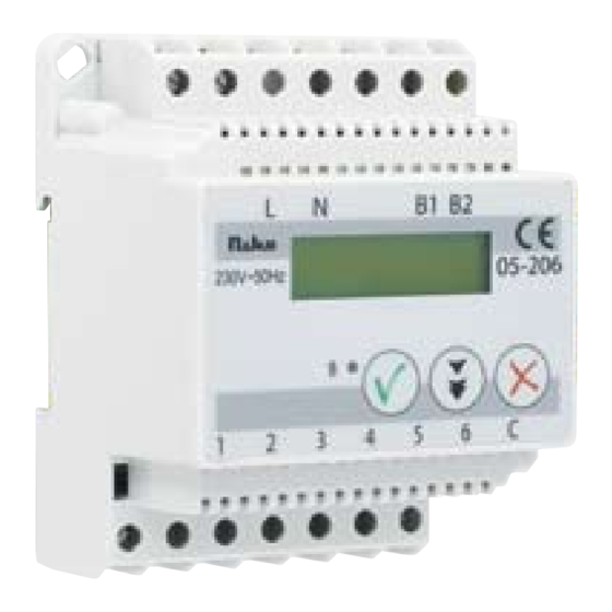
    Lisez entièrement le mode d’emploi avant toute installation et mise en service. 1. FONCTIONNEMENT ET DESCRIPTION DU PRODUIT Le module d’entrée binaire Nikobus (05-206) est entièrement compatible avec les produits Nikobus existants. Le module d’entrée binaire possède 6 entrées pour contacts libres de potentiel externes. Il est ainsi possible de relier les contacts externes au bus.
  • Page 14 05-206 bornes de raccordement alimentation 230V~ raccordement de câble bus polarisé B1 B2 05-206 230V~50Hz annuler/retourner avancer/défiler confirmer/sélectionner LED (activité bus) borne commune 6 entrées pour contacts libres de potentiel externes Fig. 1: module d’entrée binaire (05-206)
  • Page 15 05-206 La ‘Fig. 2’ présente une configuration possible avec le module d’entrée binaire. 230V~ Nikobus B1 B2 05-206 230V~50Hz Light sensor 350-10010 05-206 a b P K1 K2 :BUS relay Take out jumper, using three- wire system! 10-836 350-15010 Fig. 2: schéma de raccordement module d’entrée binaire...
  • Page 16: Programmation

    05-206 Lorsque la tension est raccordée pour la première fois, l’écran suivant sera affiché: Niko nv-sa BINAIR IN v1.0 Fig. 3: démarrage Après env. 8s. l’écran ‘statut’ s’affichera (voir 4. FONCTIONNEMENT). Toutes les entrées sont programmées par défaut en ‘auto mode’ (voir 3.2. ‘Mode select’).
  • Page 17 05-206 - Lorsque l’entrée souhaitée est sélectionnée et que est enfoncé brièvement (< 1,6s.), l’écran ‘mode select’ est activé. (Voir 3.2. ‘Mode select’). - Lorsque l’entrée souhaitée est sélectionnée et que est enfoncé longuement (> 1,6s.), un télégramme ‘marche’ est envoyé depuis cette entrée. Cela peut être utilisé...
  • Page 18 05-206 Les différents modes sont: - Auto mode: lorsque le contact est fermé, un télégramme ‘marche’ est placé sur le bus. Lorsque le contact est ouvert, un télégramme ‘arrêt’ est placé sur le bus. Toute modification des entrées de contact est suivie.
  • Page 19: Fonctionnement

    05-206 4. FONCTIONNEMENT Lorsque le module d’entrée binaire se trouve en mode de fonctionnement normal, l’écran ‘statut’ s’affiche: 1 2 3 4 5 6 Fig. 6: ‘statut’ Cet écran indique le statut de chaque entrée de contact. Dans cet exemple, le statut des différentes entrées est:...
  • Page 20: Caracteristiques Techniques

    05-206 - La polarité entre le module de commande, le module de volets, la commande télévariateur, l’interface modulaire RF, le PC-Link, le PC-Logic et le module d’entrée binaire doit être respectée. ‘B1’ doit toujours être relié à ‘B1’ et ‘B2’ à ‘B2’. Si ce n’est pas le cas, l’installation ne fonctionnera pas ou des erreurs peuvent se manifester.
  • Page 21: Prescriptions Legales

    - ce mode d’emploi qui doit être lu dans le cadre de toute installation spécifique; - les règles de l’art. - En cas de doute, vous pouvez appeler le service ‘support Niko’ ou vous adresser à un organisme de contrôle reconnu.
  • Page 22: Conditions De Garantie

    à un remplacement gratuit selon l’avis de Niko. - Niko ne peut être tenu pour responsable pour un défaut ou des dégâts suite à une installation fautive, à une utilisation contraire ou inadaptée ou à une transformation du produit.
  • Page 23: Installation Und Anschlüsse

    Lesen Sie vor der Montage und Inbetriebnahme die vollständige Gebrauchs- anleitung. 1. FUNKTIONSWEISE UND PRODUKTBESCHREIBUNG Das Nikobus Binäreingangsmodul (Art. Nr. 05-206) ist vollkompatibel mit den bestehenden Nikobusprodukten. Das Binäreingangsmodul besitzt 6 Eingänge für externe, potentialfreie Kontakte. Somit ist es möglich, externe Kontakte mit dem Bus zu verbinden. Jeder Eingang hat 3 unterschiedliche Programmiermöglichkeiten: auto mode, fixed on und fixed off.
  • Page 24 05-206 Anschlussklemmen Spannungsversorgung 230V~ polarisierter Busanschluss B1 B2 05-206 230V~50Hz löschen/Schritt zurück Schritt vor/scrollen bestätigen/auswählen LED (Busaktivität) gemeinsame Klemme 6 Eingänge für externe, potentialfreie Kontakte Zeichnung 1: Binäreingangsmodul (05-206)
  • Page 25 05-206 In ‘Zeichnung 2’ ist eine mögliche Anordnung mit dem Binäreingangsmodul dargestellt. 230V~ Nikobus B1 B2 05-206 230V~50Hz Light sensor 350-10010 05-206 a b P K1 K2 :BUS relay Take out jumper, using three- wire system! 10-836 350-15010 Zeichnung 2: Anschlussschema Binäreingangsmodul...
  • Page 26 05-206 Wird das Gerät zum ersten Mal an Spannung gelegt, so wird Folgendes auf dem Display angezeigt: Niko nv-sa BINAIR IN v1.0 Zeichnung 3: Inbetriebnahme Display Nach ca. 8s. wird auf dem Display ‘status’ angezeigt (siehe 4. FUNKTIONSWEISE). Alle Eingänge sind dann im ‘auto mode’ vorprogrammiert (siehe 3.2. ‘Mode select’).
  • Page 27 05-206 - Wird auf die Taste gedrückt, so werden nacheinander die unterschiedlichen Eingänge (1 bis 6) selektiert. - Ist der gewünschte Eingang ausgewählt und wurde die Taste kurz (< 1,6s.) betätigt, dann wird ‘mode select’ aufgerufen. (Siehe 3.2. ‘Mode select’).
  • Page 28 05-206 Folgende unterschiedliche Modi stehen zur Verfügung: - Auto mode: Wird der Kontakt geschlossen, so wird ein ‘EIN’-Telegramm auf den Bus gesendet. Wird der Kontakt geöffnet, so wird ein ‘AUS’-Telegramm auf den Bus gesendet. Jede Statusänderung der Kontakteingänge wird übernommen.
  • Page 29: Warnhinweise Zur Installation

    05-206 5. FUNKTIONSWEISE Wenn das Binäreingangsmodul im Modus normale Betriebsweise steht, wird die Anzeige ‘status’ angezeigt: 1 2 3 4 5 6 Zeichnung 6 : ‘status’ Der Status jedes Kontakteingangs wird angezeigt. In diesem Beispiel ist der Status der einzelnen Eingänge: 1.
  • Page 30: Technische Daten

    05-206 - Die Buspolarität zwischen den Schaltmodulen, Rollladenmodulen, Dimcontrollern, Funkinter- face, PC-Link, PC-Logic und dem binären Eingangsmodul muss eingehalten werden. ‘B1’ muss immer mit ‘B1’ verbunden werden und ‘B2’ mit ‘B2’. Falls dies nicht so ausgeführt wird, kann die Anlage nicht einwandfrei arbeiten oder es können Fehler auftreten.
  • Page 31: Gesetzliche Bestimmungen

    - diese Gebrauchsanleitung die im Zusammenhang mit jeder spezifischen Anlage gesehen werden muss; - die Regeln fachmännischen Könnens. - Sollten Sie Fragen haben, können Sie sich an die Niko-Hotline oder an eine anerkannte Kontrollstelle wenden: Web-site: www.niko.be; E-Mail: support@niko.be; Hotline Belgien: +32 3 778 90 80...
  • Page 32 Bedienung oder Anpassen/Ändern des Produktes entsteht. - Die zwingenden Vorschriften der nationalen Gesetzgebung bezüglich des Verkaufs von Konsumgütern und der Schutz des Kunden in den Ländern in denen Niko direkt oder über seine Tochtergesellschaften, Filialen, Distributoren, Handelsvertretungen oder Vertretern verkauft, haben Vorrang vor den obigen Bestimmungen.
  • Page 33: Installation And Connections

    Read the complete manual before attempting installation and activating the system. 1. OPERATION AND PRODUCT DESCRIPTION The Nikobus binary input module (05-206) fully compatible with the existing Nikobus products. The binary input module has 6 inputs for external, potential free contacts. These enable the external contacts to be connected to the bus.
  • Page 34 05-206 connection terminals power supply 230V~ polarized bus connection B1 B2 05-206 230V~50Hz cancel / step backwards forwards /scroll fix / select LED (bus activity) common terminal 6 inputs for external, potential free contacts Fig. 1: binary input module (05-206)
  • Page 35 05-206 See ‘Fig. 2’ for a possible configuration with the binary input module 230V~ Nikobus B1 B2 05-206 230V~50Hz Light sensor 350-10010 05-206 a b P K1 K2 :BUS relay Take out jumper, using three- wire system! 10-836 350-15010 Fig. 2: connection diagram binary input module...
  • Page 36 05-206 If the power supply is connected for the first time, the display will show the following: Niko nv-sa BINAIR IN v1.0 Fig. 3: start up After approx. 8s., the display shows ‘status’ (see 4. OPERATION). As a standard, all inputs are programmed in ‘auto mode’.
  • Page 37 05-206 - Once the desired input is selected and is briefly (< 1,6s.) pressed, ‘mode select’ is activated (see 3.2. ‘Mode select’). - Once the desired input is selected and is pressed for a long time (> 1,6s.), an ‘on’...
  • Page 38 05-206 The different modes are: - Auto mode: If the contact is closed, an ‘on’ telegram is put on the bus. If the contact is opened, an ‘off’ telegram is put on the bus. Every change of the contact inputs is followed up.
  • Page 39 05-206 4. OPERATION If the binary input module is set in normal operation mode, the display shows ‘status’: 1 2 3 4 5 6 Fig. 6 : ‘status’ The display shows the status of every contact input. In the above example, the status of the different inputs is: 1.
  • Page 40: Technical Data

    05-206 PC Link, PC Logic and the binary input module must be observed. ‘B1’ must always be connected to ‘B1’ and ‘B2’ to ‘B2’. If this is not the case, the installation will not work or faults can occur. 6. TECHNICAL DATA Power supply: ....
  • Page 41: Legal Warnings

    +32 3 778 90 80 +44 1525877707 website : http://www.niko.be http://www.nikouk.com e-mail: support@niko.be sales@nikouk.com In case of a defect, you can return your product to a registered Niko wholesaler, together with a clear description of your complaint (Conditions of use, stated defect…).
  • Page 42: Guarantee Provisions

    - In case of a failure to conform, the consumer has the right to a repair or replacement (decided by Niko) free of charge. - Niko cannot be held liable for a defect or damage as a result of an incorrect installation, improper or careless use or wrong usage or transformation of the goods.
  • Page 44 Niko sa Industriepark West 40, BE-9100 Sint-Niklaas, Belgium tel.+ 32 3 778 90 00 - fax + 32 3 777 71 20 e-mail: support@niko.be - www.niko.be PM005-20600R08443...

Table des Matières