Heath Zenith SL-6133 Mode D'emploi
Table des Matières
Les langues disponibles
Les langues disponibles
Liens rapides
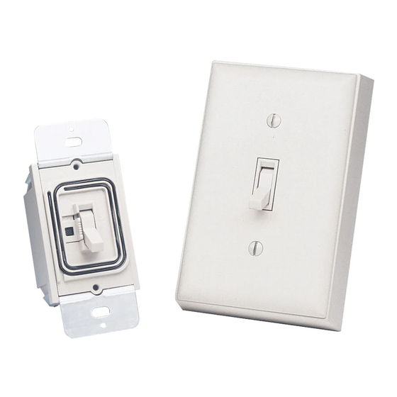
Wireless Add-on Switch
Model SL-6133
Y
our wireless add-on switch includes:
• 1 transmitter wall switch unit
• 1 receiver wall switch unit
• 2 wire connectors
• 2 #8 x 2" wood screws
You'll need to buy a 9-volt alkaline battery for the wireless switch. In typical
use, this battery will last one year.
Multiple channels (A thru E) are available so that you can operate several
systems at different locations in your home. If you purchase more than one
system, make sure you select different operating channels, or they will inter-
act with each other.
If you purchase a different switch plate to match your decor, make sure it is not a
metal plate. Metal wall plates will reduce the operating range.
IMPORTANT: Use only as a second switch to remotely control a light. Do
not use if more than one switch exists.
1.
Select a wall switch location that controls a light or overhead incandescent light.
Keep the following points in mind while selecting a location:
• Never install two receiver units within 3 feet (0.9 m) of each other or it could
reduce the operating range.
• The total lighting load must not exceed 500 watts (incandescent only).
• The receiver must be located within the range of the transmitter (up to 100
feet [30 m]) in the room or hallway that they are installed so they will operate
properly.
• Make sure that large metal objects are not located between the transmitter and
receiver since it could interfere with the signals.
2. Turn off the power to the light switch circuit before you proceed. Do this
at your circuit breaker or fuse box.
© 2003 DESA Specialty Products™
Installation
595-4918-05
Table des Matières
Dépannage

Manuels Connexes pour Heath Zenith SL-6133

Sommaire des Matières pour Heath Zenith SL-6133
- Page 7 595-4918-05...
- Page 14 -14- 595-4918-05...
-
Page 15: Interrupteur Rapporté Sans File Modèle Sl-6133
Interrupteur rapporté sans file Modèle SL-6133 Votre interrupteur rapporté sa fil comprend: • 1 transmitter wall switch unit • 1 receiver wall switch unit • 2 wire connectors • 2 #8 x 2" wood screws ll vous faudra acheter une pile alcaline de 9V pour l’interrupteur sans fil. En utilisation type, cette pile durera un an. - Page 16 3. Enlevez l’interrupteur existant et sa plaque et débranchez ses deux fils. Conservez la plaque et les vis pour réinstallation ultérieure. Si plus de deux fils sont attachés à l’interrupteur, consultez un électricien. De plus, le code du bâtiment de votre région pourrait exiger que l’installation soit faite par un électricien reconnu.
- Page 17 Interrupteur Principal Interrupteur à Bascule Figure 2 - Interrupteur Principal du Récepteur 9. S’il n’est pas déjà là, glissez l’interrupteur principal du récepteur, situé à côté de l’interrupteur à bascule, à sa position ON (haut). Le luminaire pourrait s’allumer à ce moment-là. NOTE: Si l’interrupteur commande un luminaire, assurez-vous de le connecter à...
- Page 18 Boîte de Jonction Antenne Figure 3 - Antenne Réceptrice 16. Installez la plaque d’interrupteur, incluse avec l’émetteur, sur l’émetteur à l’aide des vis incluses. 17. Installez la plaque d’interrupteur (non incluse) sur le récepteur à l’aide des vis enlevées précédemment. Ceci complète l’installation. Compartiment de la Pile Plaque...
-
Page 19: Guide De Dépannage
Guide De Dépannage CAUSE POSSIBLE SYMPTÔME 1. Le disjoncteur ou le fusible est hors tension. L’éclairage ne s’allume 2. L’interrupteur du luminaire est hors tension. pas. 3. L’ampoule est défectueuse. 4. L’interrupteur principal du récepteur est à OFF. 5. Le câblage du récepteur au câblage de la maison est desserré. -
Page 20: Informations Sur La Réglementation
Informations Sur la Réglementation L’utilisateur est informé que tout changement ou modification, non approuvé explicitement par l’organisme de réglementation pertinent, pourrait annuler le droit de l’utilisateur à faire fonctionner cet appareil. Ce dispositif est conforme aux exigences de RSS-210 d’Industrie Canada. Son fonctionnement est sujet aux deux conditions suivantes: 1) Ce dispositif ne doit pas causer de parasites nuisibles, et 2) Ce dispositif doit endurer tous les parasites reçus, y compris ceux susceptibles de provoquer un fonctionnement intempestif.