Napoleon B46NTR Instructions D'installation Et D'utilisation
Table des Matières
Les langues disponibles
Les langues disponibles
Liens rapides
INSTALLER: LEAVE THIS MANUAL WITH THE APPLIANCE.
CONSUMER: RETAIN THIS MANUAL FOR FUTURE REFERENCE.
NEVER LEAVE CHILDREN OR OTHER AT RISK INDIVIDUALS ALONE WITH THE APPLIANCE
CERTIFIED UNDER CANADIAN AND AMERICAN NATIONAL STANDARDS: CSA 2.22 AND ANSI Z21.50 FOR VENTED DECORATIVE GAS FIREPLACES.
ADD SAFETY STANDARD INFORMATION...
SAFETY INFORMATION
WARNING
!
If the information in these instructions
are not followed exactly, a fi re or
explosion may result causing property
damage, personal injury or loss of life.
- Do not store or use gasoline or other fl ammable
vapors and liquids in the vicinity of this or any
other appliance.
- WHAT TO DO IF YOU SMELL GAS:
•
Do not try to light any appliance.
•
Do not touch any electrical switch; do not use
any phone in your building.
•
Immediately call your gas supplier from a
neighbour's phone. Follow the gas supplier's
instructions.
•
If you cannot reach your gas supplier, call the
fi re department.
- Installation and service must be performed by a
qualifi ed installer, service agency or the supplier.
This appliance may be installed in an aftermarket,
permanently located, manufactured home (USA
only) or mobile home, where not prohibited by
local codes.
This appliance is only for use with the type of gas
indicated on the rating plate. This appliance is
not convertible for use with other gases, unless a
certifi ed kit is used.
Wolf Steel Ltd., 24 Napoleon Rd., Barrie, ON, L4M 0G8 Canada /
Phone 1 (866) 820-8686 • www.napoleonfi replaces.com • hearth@napoleonproducts.com
$10.00
INSTALLATION AND
OPERATING INSTRUCTIONS
A barrier designed to reduce the risk of burns from
the hot viewing glass is provided with this appliance
and shall be installed for the protection of children
and other at-risk individuals.
103 Miller Drive, Crittenden, Kentucky, USA, 41030
B46NTR / B46NTRE
NATURAL GAS MODEL
B46PTR / B46PTRE
PROPANE GAS MODEL
ADD
PRODUCT
IMAGE
FOR INDOOR USE ONLY!
DANGER
!
HOT GLASS WILL CAUSE
DO NOT TOUCH GLASS UNTIL
NEVER ALLOW CHILDREN TO
AVERTISSEMENT
!
OMNI or CSA
LOGO HERE
LA VITRE CHAUDE CAUSERA
NE PAS TOUCHER LA VITRE
AVANT QU'ELLE AIT REFROIDI.
NE JAMAIS LAISSER LES
ENFANTS TOUCHER LA VITRE.
BURNS.
COOLED.
TOUCH GLASS.
ADD ETL,
DES BRÛLURES.
1.1A
W415-1613 / D / 09.20.17
EN
FR
PG
69
Chapitres
Table des Matières
Dépannage

Manuels Connexes pour Napoleon B46NTR


Sommaire des Matières pour Napoleon B46NTR
-
Page 67: Notes
17.0 NOTES 44.1... - Page 68 NAPOLEON CELEBRATING OVER 40 YEARS OF HOME COMFORT PRODUCTS 7200, Route Transcanadienne, Montréal, Québec H4T 1A3 24 Napoleon Road, Barrie, Ontario, Canada L4M 0G8 214 Bayview Drive, Barrie, Ontario, Canada L4N 4Y8 103 Miller Drive, Crittenden, Kentucky, USA 41030 Phone: 1-866-820-8686...
-
Page 69: Consignes De Sécurité
ADD ETL, ÉCRAN DE OMNI or CSA PROTECTION LOGO HERE Wolf Steel Ltd., 24 Napoleon Rd., Barrie, ON, L4M 0G8 Canada / 103 Miller Drive, Crittenden, Kentucky, USA, 41030 Téléphone 1 (866) 820-8686 • www.napoleonfoyers.com • hearth@napoleonproducts.com 10,00 $ 1.1A... - Page 70 TABLE DES MATIÈRES VUE D'ENSEMBLE DE L'INSTALLATION INTRODUCTION DIMENSIONS INSTRUCTIONS GÉNÉRALES INFORMATIONS GÉNÉRALES INFORMATION À PROPOS DE LA PLAQUE D’HOMOLOGATION ÉVACUATION LONGUEURS DES CONDUITS D’ÉVACUATION ET COMPOSANTS INSTALLATIONS TYPIQUES D'ÉVENTS INSTALLATIONS PARTICULIÈRES D'ÉVENTS 3.3.1 ENSEMBLE PÉRISCOPIQUE 3.3.2 INSTALLATION EN COIN EMPLACEMENTS ET DÉGAGEMENTS MINIMAUX DE LA TERMINAISON CHARTE D'APPLICATION DES ÉVACUATIONS LÉGENDE...
-
Page 71: Vue D'ensemble De L'installation
1.0 VUE D'ENSEMBLE DE L'INSTALLATION Voir la section « DÉGAGEMENTS MINIMAUX DE L’ENCEINTE » pour les cloisons sèches (ou autre matériau combustible). Voir la section « DÉGAGEMENTS MINIMAUX DE LA TABLETTE ». Voir les sections « ÉVACUATION » et « INSTALLATION ». Voir la section «... -
Page 72: Introduction
2.0 INTRODUCTION AVERTISSEMENT • CET APPAREIL EST CHAUD LORSQU’IL FONCTIONNE ET PEUT CAUSER DE GRAVES BRÛLURES EN CAS DE CONTACT. • TOUTE MODIFICATION APPORTÉE À CET APPAREIL OU AUX CONTRÔLES PEUT ÊTRE DANGEREUX ET SONT INTERDIT. AVERTISSEMENT • Ne faites pas fonctionner l’appareil avant d’avoir lu et compris les instructions d’opération. Omettre d’utiliser l’appareil selon les instructions d’opération pourrait causer un incendie ou des blessures. -
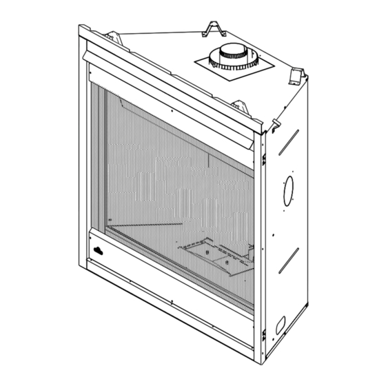
Page 73: Dimensions
DIMENSIONS W415-1613 / D / 09.20.17... -
Page 74: Instructions Générales
INSTRUCTIONS GÉNÉRALES AVERTISSEMENT ALLUMEZ TOUJOURS LA VEILLEUSE, QUE CE SOIT POUR LA PREMIÈRE FOIS OU LORSQUE L’APPROVISIONNEMENT EN GAZ EST ÉPUISÉ, AVEC LA PORTE VITRÉE OUVERTE OU RETIRÉE. PRÉVOYEZ UN ACCÈS SUFFISANT POUR ENTRETENIR ET OPÉRER L’APPAREIL. ASSUREZ-VOUS D'UNE QUANTITÉ SUFFISANTE D’AIR DE VENTILATION. N’OBSTRUEZ JAMAIS L’OUVERTURE DE L’APPAREIL. -
Page 75: Informations Générales
Cet appareil est approuvé pour installation dans les salles de bain, les chambres à coucher ou les chambres studio et convient pour installation dans les maisons mobiles. CODES PRODUITS B46NTR ET B46PTR SEULEMENT : Aucune alimentation électrique externe (110 volts ou 24 volts) n'est requise pour le fonctionnement du système. Toutefois, c'est requis avec l'installation d'une soufflerie optionnelle. -
Page 76: Information À Propos De La Plaque D'homologation
NECESSARY AFTER SERVICING THE VENT-AIR INTAKE SYSTEM. BACK / ARRIERE VENT BOTTOM / EVENT INFERIEUR 1" L'APPAREIL DOIT EVACUER SES GAZ EN UTILISANT L'ENSEMBLE D'EVACUATION PROPRE A NAPOLEON. MANTEL / MANTEAU 2" * REFERER AU MANUEL D'INSTALLATION DE PROPRIETAIRE POUR L'EVACUATION PRECISE. IL EST * MAXIMUM HORIZONTAL EXTENSION / L'EXTENSION HORIZONTALE MAXIMALE: 2". -
Page 77: Évacuation
3.0 ÉVACUATION AVERTISSEMENT RISQUE D’INCENDIE. CONSERVEZ LES DÉGAGEMENTS NÉCESSAIRES AU CONDUIT D’ÉVENT ET À L’APPAREIL. SI LE SYSTÈME D’ÉVENT EST FOURNI AVEC DES ESPACEURS, LES COURSES HORIZONTALES ET VERTICALES DU SYSTÈME DOIVENT ÊTRE SUPPORTÉES À TOUS LES 3 PI (0,9m). UTILISEZ DES SUPPORTS OU DES ATTACHES INCOMBUSTIBLES ÉQUIVALENTS AFIN DE MAINTENIR LE DÉGAGEMENT AUX MATÉRIAUX COMBUSTIBLES. -
Page 78: Longueurs Des Conduits D'évacuation Et Composants
LONGUEURS DES CONDUITS D’ÉVACUATION ET COMPOSANTS Utilisez uniquement des composants d’évacuation Wolf Steel, Simpson Dura-Vent, Selkirk Direct Temp, American Metal Amerivent ou Metal-Fab. Les minimums et maximums des longueurs d’évent, pour les installations verticales et horizontales, et les emplacements des terminaisons pour les deux systèmes sont précisés dans ce manuel et doivent être respectés. -
Page 79: Installations Typiques D'évents
INSTALLATIONS TYPIQUES D'ÉVENTS 16" (40,6CM) MINIMUM 40 FT (12M) MAXIMUM 3 FT (1M) 24" (61CM) MINIMUM MAXIMUM 8" (203MM) MINIMUM 42 5/8" (108,3CM) MINIMUM PLUS LA PENTE 34 5/8" 34 5/8" (87,9CM) (87,9CM) ÉVACUATION SUR LE DESSUS * Voir la section « ÉVACUATION » W415-1613 / D / 09.20.17... - Page 80 16" (40,6CM) MINIMUM 40 FT (12M) MAXIMUM 3 FT (1M) MINIMUM 20" (50,8CM) 24 1/8" 24 1/8" (61,3CM) (61,3CM) PLUS LA PENTE ÉVACUATION SUR L’ARRIÈRE * Voir la section « ÉVACUATION » 415-1613 / D / 09.20.17...
-
Page 81: Installations Particulières D'évents
INSTALLATIONS PARTICULIÈRES D'ÉVENTS 3.3.1 ENSEMBLE PÉRISCOPIQUE Use the periscope kit to locate the air termination above grade. The periscope must be installed so that when fi nal grading is completed, the bottom air slot is located a minimum 12” (30.5cm) above grade. The maximum allowable vent length is 10’... -
Page 82: Emplacements Et Dégagements Minimaux De La Terminaison
EMPLACEMENTS ET DÉGAGEMENTS MINIMAUX DE LA TERMINAISON APPLICATIONS POUR BALCON COUVERT ††* INSTALLATION = 3 pieds ≤ 15 pieds = 2 x RÉELLE (4,6m) (0,9m) CANADA É.-U. 12” (30,5cm) 12” (30,5cm) Dégagement au-dessus du sol, d’une véranda, d’une terrasse en bois ou d’un balcon. 12”... -
Page 83: Charte D'application Des Évacuations
CHARTE D'APPLICATION DES ÉVACUATIONS ÉVACUATION SUR LE DESSUS Terminaison horizontale Terminaison verticale La course verticale La course verticale La course verticale est La course verticale est est plus petite que la plus grande ou égale à est plus petite que la plus grande ou égale à... -
Page 84: Légende
LÉGENDE Les symboles suivants sont utilisés dans le calcul et les exemples d’évacuation : > - plus grand que > - plus grand ou égal à < - plus petit que < - plus petit ou égal à - total de la longueur des courses horizontales (Hr) et des déviations (Ho) en pieds - longueur des courses horizontales combinées en pieds - facteur de la valeur d’une déviation : 0,03 (du total des degrés de déviation - 90°*) en pieds - longueur des courses verticales combinées en pieds... - Page 85 ) > (V Configuration d'évacuation simple Consultez le graphique pour déterminer la course verticale nécessaire V par rapport à la course horizontale requise H (un coude de 90° seulement) 150 (381) 147 (373) COURSE VERTICALE 100 (254) REQUISE EN POUCES (CENTIMÈTRES)V 57 (145) 50 (127)
-
Page 86: Évacuation À L'arrière Terminaison Horizontale
ÉVACUATION À L'ARRIÈRE TERMINAISON HORIZONTALE ) < (V Configuration d'évacuation simple Consultez le graphique pour déterminer la course verticale nécessaire (deux coudes de 90° seulement) par rapport à la course horizontale requise H 40 (12,2) 38,3 (11,7) COURSE 30 (9,1) VERTICALE REQUISE EN PIEDS... - Page 87 ) > (V Configuration d'évacuation simple Consultez le graphique pour déterminer la course verticale (deux coudes de 90° seulement) nécessaire V par rapport à la course horizontale requise H 150(3810) 12,5 (3,8) 147 (3733.8 12,25 (3,7) COURSE VERTICALE 100 (2540) 8,3 (2,54) REQUISE EN PIEDS...
-
Page 88: Évacuation Sur Le Dessus Ou À L'arrière Terminaison Verticale
3.10 ÉVACUATION SUR LE DESSUS OU À L'ARRIÈRE TERMINAISON VERTICALE ) < (V Consultez le graphique pour déterminer la course verticale Configurations d'évacuation simples. nécessaire V par rapport à la course horizontale requise H 40 (12,2) 30 (9,1) COURSE VERTICALE 20 (6,1) REQUISE EN PIEDS... - Page 89 ) > (V ) > (V Configurations d'évacuation simples. Consultez le graphique pour déterminer la course verticale Configurations d'évacuation simples. Consultez le graphique pour déterminer la course verticale nécessaire V par rapport à la course horizontale requise H nécessaire V par rapport à...
-
Page 90: Évacuation À L'arrière
3.11 ÉVACUATION À L'ARRIÈRE AVERTISSEMENT IL EST ESSENTIEL QUE LE COUVERCLE D’ÉVACUATION SOIT INSTALLÉ, SI NON L’APPAREIL NE FONCTIONNERA PAS CORRECTEMENT ET POURRAIT CAUSER DES BLESSURES OU DES DOMMAGES MATÉRIELS. Fig. 1 Enlevez l'écran de protection et vitre de la porte, référer de la section, «... -
Page 91: Évacuation Sur Le Dessus
3.13 ÉVACUATION SUR LE DESSUS AVERTISSEMENT FLUE PIPE WITH GASKET JOINT IL EST ESSENTIEL QUE LE COUVERCLE D’ÉVACUATION SOIT INSTALLÉ, SI NON L’APPAREIL NE D’ÉTANCHÉITÉ TO TOP VENT FONCTIONNERA PAS CORRECTEMENT ET POURRAIT CAUSER DES BLESSURES OU DES DOMMAGES MATÉRIELS. COLLET D’ÉVACUATION NOTE: Cet appareil a été... -
Page 92: Installation
4.0 INSTALLATION AVERTISSEMENT AVANT D’EFFECTUER LES BRANCHEMENTS POUR L’ALIMENTATION EN GAZ ET ÉLECTRIQUE, ASSUREZ-VOUS DE RETIRER TOUTE COMPOSANTE NON FIXÉE À L’INTÉRIEUR DE LA CHAMBRE DE COMBUSTION. SI VOTRE APPAREIL COMPREND UN SYSTÈME DE TÉLÉCOMMANDE, ASSUREZ-VOUS QUE LE RÉCEPTEUR EST À LA POSITION « OFF » AVANT D’EFFECTUER LES BRANCHEMENTS POUR L’ALIMENTATION EN GAZ ET ÉLECTRIQUE. -
Page 93: Installation Horizontale
4.1.1 INSTALLATION HORIZONTALE AVERTISSEMENT L’ESPACEUR COUPE-FEU DOIT ÊTRE INSTALLÉ AVEC L’ÉCRAN PROTECTEUR ORIENTÉ VERS LE HAUT. LA TERMINAISON NE DOIT PAS ÊTRE ENCHÂSSÉE DANS LE MUR OU LE REVÊTEMENT EXTÉRIEUR PLUS QUE L’ÉPAISSEUR DE LA BRIDE DE LA PLAQUE DE MONTAGE. Cette confi guration s’applique lorsque le conduit d’évent traverse Dimensions de L'Ossature du un mur extérieur. -
Page 94: Utilisation De Composants Flexibles D'évacuation
UTILISATION DE COMPOSANTS FLEXIBLES D’ÉVACUATION UTILISATION DE COMPOSANTS FLEXIBLES D’ÉVACUATION AVERTISSEMENT AVERTISSEMENT NE LAISSEZ PAS LA GAINE FLEXIBLE SE TASSER CONTRE LES COURSES HORIZONTALES OU VERTICALES NE LAISSEZ PAS LA GAINE FLEXIBLE SE TASSER CONTRE LES COURSES HORIZONTALES OU VERTICALES ET LES COUDES. -
Page 95: Installation De La Terminaison Verticale
4.2.2 INSTALLATION DE LA TERMINAISON VERTICALE 4.2.2 INSTALLATION DE LA TERMINAISON VERTICALE AVERTISSEMENT CONSERVEZ UN ESPACE MINIMAL DE 2" (51mm) ENTRE LA BASE DE LA PRISE D’AIR ET LE COLLET DE SOLIN. Fixez le support de toit au toit à l’aide des vis fournies. Le support de toit est optionnel. -
Page 96: Utilisation De Composants Rigides D'évacuation
UTILISATION DE COMPOSANTS RIGIDES D’ÉVACUATION Le système d’évacuation doit être soutenu à peu près tous les 3 pieds (0.9m) de courses verticales et horizontales. Utilisez l’ensemble de support mural Wolf Steel ou des supports incombustibles équivalents afi n de conserver le dégagement minimal aux matériaux combustibles pour les courses verticales et horizontales. Tous les joints des conduits intérieurs et extérieurs peuvent être scellés avec du scellant de silicone rouge à... -
Page 97: Installation De La Terminaison Verticale
4.3.2 INSTALLATION DE LA TERMINAISON VERTICALE Mettez l’appareil en place. CONDUIT Fixez le support de toit au toit à l’aide des vis fournies. Le support de INTÉRIEUR toit est optionnel. Dans ce cas, l’évent doit être supporté adéquatement, soit en utilisant une méthode alternative se conformant aux normes des autorités compétentes, soit en utilisant le support de toit optionnel. -
Page 98: Renstreignant Des Évents Verticaux
4.3.3 RENSTREIGNANT DES ÉVENTS VERTICAUX AVERTISSEMENT METTEZ HORS TENSION DE GAZ ET DE L'ALIMENTATION ÉLECTRIQUE AVANT D'INTERVENIR SUR L'APPAREIL. APPAREIL PEUT ÊTRE CHAUD, PAS DE SERVICE JUSQU'À CE QUE L'APPAREIL EST REFROIDI. AVERTISSEMENT POUR UNE UTILISATION SÛRE ET CORRECTE DE L'APPAREIL, SUIVEZ LES INSTRUCTIONS D'ÉVACUATION EXACTEMENT POUR ÉVITER LE RISQUE D'ASPHYXIE PAS LE SAC D'EMBALLAGE DE BÉBÉS ET LES ENFANTS. -
Page 99: Terminaison Verticale À Travers Une Cheminée Existante
TERMINAISON VERTICALE À TRAVERS UNE CHEMINÉE EXISTANTE AVERTISSEMENT RISQUE D'INCENDIE! LES CONFIGURATIONS D'ÉVACUATION COAXIALES À COLINÉAIRES NE DOIVENT ÊTRE UTILISÉES QUE DANS UNE CHEMINÉE OU UNE ENCEINTE DE NATURE INCOMBUSTIBLE. UNE INSTALLATION DANS UNE ENCEINTE COMBUSTIBLE PEUT CAUSER UN INCENDIE. Cet appareil est conçu pour être raccordé... -
Page 100: Installation Dans Une Maison Mobile
INSTALLATION DANS UNE MAISON MOBILE INSTALLATION DANS UNE MAISON MOBILE Cet appareil doit être effectuée en respectant les directives du fabricant et le Manufactured Home Construction and Safety Standard, Title 24 CFR, Part 3280, aux États-Unis, ou les normes actuelles pour les maisons mobiles, CAN/CSA Z240 SÉRIE MH, au Canada. -
Page 101: Branchement Du Gaz
BRANCHEMENT DU GAZ AVERTISSEMENT RISQUE D'INCENDIE, D'EXPLOSION OU D'ASPHYXIE. ASSUREZ-VOUS QU'IL N'Y AIT AUCUNE SOURCE D'ALLUMAGE COMME DES ÉTINCELLES OU UNE FLAMME NUE. SOUTENEZ LE CONTRÔLE DU GAZ LORSQUE VOUS ATTACHEZ LE TUYAU POUR ÉVITER DE PLIER LA CONDUITE DE GAZ. ALLUMEZ TOUJOURS LA VEILLEUSE, QUE CE SOIT POUR LA PREMIÈRE FOIS OU LORSQUE L’APPROVISIONNEMENT EN GAZ EST ÉPUISÉ, AVEC LA PORTE VITRÉE OUVERTE OU RETIRÉE. -
Page 102: Ossature
5.0 OSSATURE Lorsque vous installez les accessoires de finition optionnelles, les dimensions de l'ossature et les matériaux de finition peuvent différer de ce qui est décrit dans ces instructions ci-dessous, voir les instructions fournies dans le trousse de l'accesoire pour les spécifications détaillées. AVERTISSEMENT RISQUE D’INCENDIE! AFIN D’ÉVITER LA POSSIBILITÉ... -
Page 103: Dimensions Minimales De L'ossature
DIMENSIONS MINIMALES DE L’OSSATURE 50 1/2" 128,3cm 35" 88,9cm 18 9/16" 47,1cm W415-1613 / D / 09.20.17... - Page 104 Dégagements minimaux de l'appareil aux matériaux combustibles : Ossature combustible : 0" aux espaceurs 1" (25mm) en dessous et sur les côtés du conduit d’évent* 3" (76mm) au-dessus du conduit d’évent* Finition combustible : 0" à l’arrière 0" des côtés et du dessus en façade Évacuation sur le dessus 50 1/2"...
-
Page 105: Dégagements Minimaux De L'enceinte
DÉGAGEMENTS MINIMAUX DE L'ENCEINTE ÉVACUATION SUR LE DESSUS ENCEINTE AVEC ÉVACUATION SUR LE DESSUS L'enceinte de l'appareil doit avoir une hauteur minimale de 50 1/2" (128,3cm). Afin de respecter les constraintes de température, l'espace à l'intérieur de l'enceinte, autour de l'appareil et au-dessus, doit de- meurer sans obstruction. -
Page 106: Enceinte Avec Évacuation À L'arrière
ÉVACUATION À L'ARRIÈRE Pour la ventilation arrière ne dépassement pas 10" (254mm) de section horizontale de ventilation. ENCEINTE AVEC ÉVACUATION À L'ARRIÈRE L'enceinte de l'appareil doit avoir une hauteur minimale de 41 5/8" (105,7cm). Afin de respecter les contraintes de température, l’espace à l’intérieur de l’enceinte, autour de l'appareil et au-dessus, doit demeurer sans obstruction. -
Page 107: Dégagements Maximaux De Évacuation À L'arrière (Exemple 1)
DÉGAGEMENTS MAXIMAUX DE ÉVACUATION À L'ARRIÈRE (EXEMPLE 1) ENCEINTE AVEC ÉVACUATION À L'ARRIÈRE L'enceinte de l'appareil doit avoir une hauteur minimale de 41 5/8" (105,7cm). Afin de respecter les contraintes de température, l’espace à l’intérieur de l’enceinte, autour de l'appareil et au-dessus, doit demeurer sans obstruction. -
Page 108: Dégagements Maximaux De Évacuation À L'arrière (Exemple 2)
DÉGAGEMENTS MAXIMAUX DE ÉVACUATION À L'ARRIÈRE (EXEMPLE 2) 24 1/8" (613MM) PLUS LA PENTE* ENCEINTE AVEC ÉVACUATION À L'ARRIÈRE L'enceinte de l'appareil doit avoir une hauteur minimale de 41 5/8" (105,7cm). Afin de respecter les contraint- es de température, l’espace à l’intérieur de l’enceinte, autour de l'appareil et au-dessus, doit demeurer sans obstruction. -
Page 109: Matériau De Finition Incombustible
MATÉRIAU DE FINITION INCOMBUSTIBLE AVERTISSEMENT: Les matériaux de finition incombustibles ne doivent pas dépasser de plus 4” (101,6mm) la façade de la porte (sur toutes côtés). Si des projections plus grandes sont requises, augmentez les dégagements des côtés et du dessus de 2" (50,1mm) pour chaque pouce (24,5mm) supplémentaire de projection. -
Page 110: Installation Encadrée
5.5 INSTALLATION ENCADRÉE AVERTISSEMENT L’INSTALLATION D’UNE TÉLÉVISION OU D’AUTRES APPAREILS ÉLECTRONIQUES DESSUS DE L’APPAREIL PEUT PROVOQUER LA DÉCOLORATION, FUSION OU DOMMAGE L’APPAREIL ÉLECTRONIQUE. UTILISER LES DÉGAGEMENTS À TITRE INDICATIF ET SE RÉFÉRER AUX AVERTISSEMENT INSTRUCTIONS DE VOTRE FABRICANT POUR PLUS D’INFORMATIONS. DÉGAGEMENTS MINIMUM 6"... -
Page 111: Dégagements Minimaux De La Tablette
8” (20.3cm) TABLETTE 8” (20.3cm) TABLETTE INCOMBUSTIBLE COMBUSTIBLE INCOMBUSTIB COMBUSTIBLE 6” (15.2cm) 6” (15.2cm) 4” (10.2cm) 18” 4” (10.2cm) 18” 2” (5.1cm) DÉGAGEMENTS MINIMAUX DE LA TABLETTE 2” (5.1cm) (45.7cm) (45.7cm) 2" TOP OF APPLIANCE MATÉRIAU TABLETTE 2" 16” MATÉRIAU TABLETTE 2"... -
Page 112: Finitions
6.0 FINITIONS Lorsque vous installez les accessoires de finition optionnelles, les dimensions de l'ossature et les matériaux 6.0 FINITIONS de finition peuvent différer de ce qui est décrit dans ces instructions ci-dessous, voir les instructions fournies dans le trousse de l'accesoire pour les spécifications détaillées. Lorsque vous installez les accessoires de finition optionnelles, les dimensions de l'ossature et les matériaux AVERTISSEMENT de finition peuvent différer de ce qui est décrit dans ces instructions ci-dessous, voir les instructions fournies... -
Page 113: L'avant Hotte D'installation
Laissez une main sur la porte vitrée pendant l'enlèvement de la porte. La porte vitrée est maintenue en place par trois loquets située en haut et trois loquets en bas de la porte. Tirez les poignées des loquets vers l’avant, puis retirez les loquets du cadre de porte afin de libérer le haut de la porte. -
Page 114: Disposition Des Bûches
DISPOSITION DES BÛCHES AVERTISSEMENT OMETTRE DE POSITIONNER LES BÛCHES CONFORMÉMENT AUX SCHÉMAS OU OMETTRE D’UTILISER UNIQUEMENT DES BÛCHES SPÉCIFIQUEMENT APPROUVÉES POUR CET APPAREIL PEUT CAUSER DES DOMMAGES MATÉRIELS OU DES BLESSURES CORPORELLES. LES BÛCHES DOIVENT ÊTRE PLACÉES CORRECTEMENT À L’INTÉRIEUR DE L’APPAREIL. NE CHANGEZ PAS LA POSITION DES BÛCHES CAR L’APPAREIL RISQUE DE NE PAS FONCTIONNER ADÉQUATEMENT ET UN RETARD D’ALLUMAGE RISQUE DE SE PRODUIRE. -
Page 115: Braises Incandescentes
Placez la bûche croisé gauche supérieure Placez la bûche de charbon gauche (W135- (W135-0696) sur le goujon sur le côté gauche 0699) à la gauche de la bûche centrale gauche de la bûche arrière et reposez-le sur la bûche sur le côté gauche du foyer. centrale gauche. -
Page 116: Installation Du Sauvegarde De Pile
INSTALLATION DU SAUVEGARDE DE PILE AVERTISSEMENT COUPEZ L’ALIMENTATION EN GAZ ET L’ALIMENTATION ÉLECTRIQUE DE L’APPAREIL L’APPAREIL PEUT ÊTRE CHAUD, NE TOUCHEZ PAS L’APPAREIL JUSQU’À CE QU’ELLE AIT REFROIDI. AVERTISSEMENT NOTE: En cas d’une panne de courrant votre appareil peut fonctionner utilisant le sauvegarde de pile fourni. -
Page 117: Installation De Soufflerie Optionnel
INSTALLATION DE SOUFFLERIE OPTIONNEL AVERTISSEMENT ASSUREZ-VOUS QUE L’APPAREIL EST COMPLÈTEMENT REFROIDI AVANT DE COMMENCER L’INSTALLATION . AFIN D’ÉVITER LES RISQUES DE SUFFOCATION, GARDEZ LE SAC D’EMBALLAGE LOIN DES BÉBÉS ET DES JEUNES ENFANTS. NE LE LAISSEZ PAS TRAÎNER DANS LES BERCEAUX, LES LITS, LES POUSSETTES OU LES AVERTISSEMENT PARCS DE JEU. -
Page 118: Schéma De Câblage
7.0 SCHÉMA DE CÂBLAGE SCHÉMA DE CÂBLAGE ÉLECTRONIQUE AVERTISSEMENT NE RACCORDEZ PAS L’INTERRUPTEUR MURAL OU LA SOUPAPE DE GAZ À L’ALIMENTATION ÉLECTRIQUE (110 VOLTS) Cette appareil est fourni avec une sauvegarde de pile. Si la sauvegarde est utilisé, installez 4 piles « AA » (non-fourni) dans la boîtier de piles et connectez au harnais de fi l. -
Page 119: Fonctionnement (Électronique)
8.0 FONCTIONNEMENT (ÉLECTRONIQUE) AVERTISSEMENT SI CES INSTRUCTIONS NE SONT PAS SUIVIES À LA LETTRE, UN INCENDIE OU UNE EXPLOSION POURRAIENT S’ENSUIVRE, CAUSANT DES DOMMAGES MATÉRIELS,DES BLESSURES CORPORELLES OU DES PERTES DE VIE. ALLUMEZ TOUJOURS LA VEILLEUSE, QUE CE SOIT POUR LA PREMIÈRE FOIS OU LORSQUE L’APPROVISIONNEMENT EN GAZ EST ÉPUISÉ, AVEC LA PORTE VITRÉE OUVERTE OU RETIRÉE. -
Page 120: Fonctionnement (Millivolt)
9.0 FONCTIONNEMENT (MILLIVOLT) AVERTISSEMENT SI CES INSTRUCTIONS NE SONT PAS SUIVIES À LA LETTRE, UN INCENDIE OU UNE EXPLOSION POUR- RAIENT S’ENSUIVRE, CAUSANT DES DOMMAGES MATÉRIELS, DES BLESSURES CORPORELLES OU DES PERTES DE VIE. ALLUMEZ TOUJOURS LA VEILLEUSE, QUE CE SOIT POUR LA PREMIÈRE FOIS OU LORSQUE L’APPROVISIONNEMENT EN GAZ EST ÉPUISÉ, AVEC LA PORTE VITRÉE OUVERTE OU RETIRÉE. -
Page 121: Réglages
PILOT ELECTRODE BURNER 10.0 RÉGLAGES 3/8” - 1/2” (9.5mm - 12.7mm) 10.0 RÉGLAGES MILLIVOLT 10.1 RÉGLAGE DE LA VEILLEUSE ILLUSTRÉ FLAME 10.1 RÉGLAGE DE LA VEILLEUSE 3/8” - 1/2” SENSOR Ajustez la vis de la veilleuse pour obtenir une fl amme de taille (9,5mm - 12,7mm) normale. -
Page 122: Caractéristiques De La Flamme
10.3 CARACTÉRISTIQUES DE LA FLAMME Il est important d’effectuer périodiquement une inspection 3/8” - 1/2” visuelle de la fl amme de la veilleuse et du brûleur. (9,5mm - 12,7mm) Comparez-les à ces illustrations. Si des fl ammes paraissent anormales, contactez un technicien de service. LA FLAMME DOIT ENVELOPPER LA PARTIE SUPÉRIEURE... -
Page 123: Entretien
11.0 ENTRETIEN AVERTISSEMENT COUPEZ L’ALIMENTATION EN GAZ ET L’ALIMENTATION ÉLECTRIQUE AVANT DE PROCÉDER À L’ENTRETIEN DE L’APPAREIL. L’APPAREIL PEUT ÊTRE CHAUD. ATTENDEZ QU’IL SOIT REFROIDI AVANT D’EN FAIRE L’ENTRETIEN. N’UTILISEZ PAS DE PRODUITS ABRASIFS. NE PEINTURE PAS L’ASSEMBLAGE DU VEILLEUSE. Assurez-vous que l’appareil fonctionne adéquatement une fois l’entretien terminé. -
Page 124: Entretien Annuel
11.1 ENTRETIEN ANNUEL AVERTISSEMENT LE CAISSON DEVIENT TRÈS CHAUD LORS DU FONCTIONNEMENT. LAISSEZ L’APPAREIL SE REFROIDIR COMPLÈTEMENT OU PORTEZ DES GANTS ANTICHALEUR AVANT D’EFFECTUER L’ENTRETIEN. AVERTISSEMENT NE JAMAIS ASPIRER DES BRAISES QUI SONT CHAUDES. NE PEINTUREZ PAS L’ASSEMBLAGE DE LA VEILLEUSE. •... -
Page 125: Soins De La Vitre
DO NOT TOUCH GLASS UNTIL COOLED. NEVER ALLOW CHILDREN TO TOUCH GLASS. 11.3 SOINS DE LA VITRE NE PAS NETTOYER LA VITRE LORSQU’ELLE EST AVERTISSEMENT CHAUDE! N’EMPLOYEZ PAS DE DÉTERGENTS ABRASIFS POUR NETTOYER LA VITRE. Polissez légèrement à l’aide d’un linge propre et sec. LA VITRE CHAUDE CAUSERA Nettoyez les deux côtés de la vitre avec un nettoyeur DES BRÛLURES. -
Page 126: Rechanges
12.0 RECHANGES AVERTISSEMENT OMETTRE DE POSITIONNER LES PIÈCES CONFORMÉMENT À CE MANUEL OU D’UTILISER UNIQUEMENT DES PIÈCES SPÉCIFIQUEMENT APPROUVÉES POUR CET APPAREIL PEUT CAUSER DES DOMMAGES MATÉRIELS OU DES BLESSURES CORPORELLES. ** CECI EST UN THERMOCOUPLE À ACTION RAPIDE QUI CONSTITUE UN COMPOSANT ESSENTIEL DE SÉCURITÉ. - Page 127 W415-1613 / D / 09.20.17...
- Page 128 415-1613 / D / 09.20.17...
- Page 129 W415-1613 / D / 09.20.17...
- Page 130 415-1613 / D / 09.20.17...
-
Page 131: Guide De Dépannage (Électronique)
14.0 GUIDE DE DÉPANNAGE (ÉLECTRONIQUE) MAINTENANCE AVERTISSEMENT MAINTENANCE MAINTENANCE ALLUMEZ TOUJOURS LA VEILLEUSE, QUE CE SOIT POUR LA PREMIÈRE FOIS OU LORSQUE L’APPROVISIONNEMENT EN GAZ EST ÉPUISÉ, AVEC LA PORTE VITRÉE OUVERTE OU RETIRÉE. COUPEZ L’ALIMENTATION EN GAZ ET L’ALIMENTATION ÉLECTRIQUE AVANT DE PROCÉDER À L’ENTRETIEN DE L’APPAREIL. - Page 132 SYMPTÔME PROBLÈME SOLUTIONS Continue de Court-circuit ou connexion Vérifi ez toutes les connexions. Vérifi ez si les connexions produire desserrée dans la tige de la de l’assemblage de la veilleuse sont serrées; vérifi ez des étincelles sonde. aussi si ces connexions ne causent pas de mise à la et la veilleuse terre au niveau du métal.
-
Page 133: Guide De Dépannage (Millivolt)
15.0 GUIDE DE DÉPANNAGE (MILLIVOLT) MAINTENANCE AVERTISSEMENT MAINTENANCE MAINTENANCE ALLUMEZ TOUJOURS LA VEILLEUSE, QUE CE SOIT POUR LA PREMIÈRE FOIS OU LORSQUE L’APPROVISIONNEMENT EN GAZ EST ÉPUISÉ, AVEC LA PORTE VITRÉE OUVERTE OU RETIRÉE. COUPEZ L’ALIMENTATION EN GAZ ET L’ALIMENTATION ÉLECTRIQUE AVANT DE PROCÉDER À L’ENTRETIEN DE L’APPAREIL. - Page 134 SYMPTÔME PROBLÉME SOLUTIONS La veilleuse ne Aucune étincelle au brûleur de Vérifi ez si la veilleuse peut être allumée avec une allumette. s’allume pas. la veilleuse. Vérifi ez si le fi l est raccordé au bouton-poussoir d’ignition. Vérifi ez si le bouton-poussoir d’ignition doit être resserré. VEILLEUSE Remplacez le fi...
-
Page 135: Garantie
16.0 GARANTIE Les produits NAPOLÉON sont fabriqués conformément aux normes strictes du Certifi cat d’Assurance de la Qualité mondialement reconnu ISO 9001 : 2008. Les produits NAPOLÉON sont conçus avec des composants et des matériaux de qualité supérieure, assemblés par des artisans qualifi és qui sont fi ers de leur travail. - Page 136 NAPOLÉON CÉLÈBRE PLUS DE 40 ANS D’EXISTENCE CONSACRÉS À LA CONCEPTION DE PRODUITS DE CONFORT 7200, Route Transcanadienne, Montréal, Québec H4T 1A3 24 Napoleon Road, Barrie, Ontario, Canada L4M 0G8 214 Bayview Drive, Barrie, Ontario, Canada L4N 4Y8 103 Miller Drive, Crittenden, Kentucky, USA 41030 Téléphone: 1-866-820-8686...