Videx 4000 Série Manuel D'installation
Masquer les pouces
Voir aussi pour 4000 Série:
- Mode d'emploi (29 pages) ,
- Manuel d'installation (21 pages) ,
- Manuel d'instructions (16 pages)
Table des Matières
Publicité
Les langues disponibles
Les langues disponibles
Liens rapides
4000 Series
Art. 4902
Digital codelock module
A
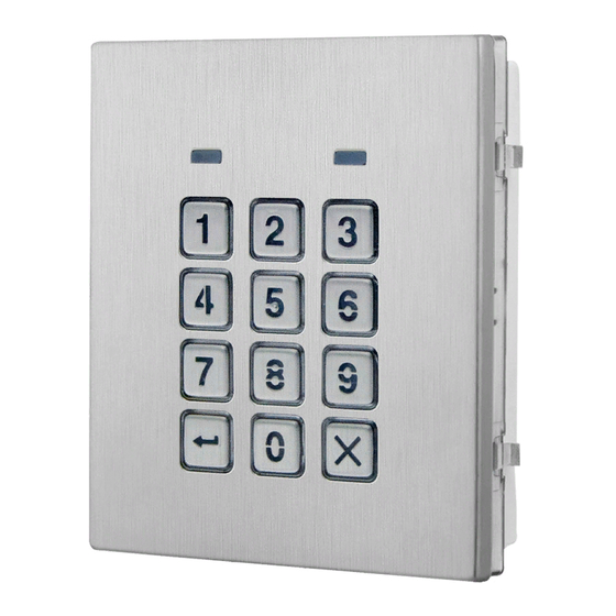
Fig. 1 Front
DESCRIPTION
The module features 12 buttons backlit keypad (Keys 0 - 9,
ENTER and CLEAR) and 2 LED's for progress information during
use and programming. The codelock unit module has 2 built-in
dry contact relays which can be used to enabling up to 2 in-
dependent services (door-open, gate-open etc.) by typing in
the programmed access codes (up to 1000) followed by enter.
Acoustic and visual (green and red LED's) confirm the use and the programming operations. This module can be used individually
or combined with other modules in a network and can also be included on an audio or video door entry system.
MAIN FEATURES
• 2 dry contact relay outputs, normally open & normally closed (24Vac/dc – 5A max);
• 1000 Programmable 8 digit access codes: each code can be set to activate relay 1, relay 2 or both;
• Each relay can be set to activate for a specific time (01 to 255 seconds) or to work in a latch mode;
• Two active low inputs to trigger relay 1 and 2 (Push to exit inputs);
• Keypad programming menu protected by a 4-8 digit programmable secret code;
• Visual and Acoustic signalling during operation and programming;
• Keypad illumination LEDs;
• PC programming facility (using specific software and RS-485 or USB cable);
• Two operating modes:
» Standard as standalone codelock or VNET LITE network with RS485 bus;
» Network as serial codelock unit connected via RS-485 to a remote control unit Art. 1050 or Art. 1052;
GENERAL DIRECTIONS FOR INSTALLATION
In order to achieve the best results from the schematics described it is necessary to install only original VIDEX equipment, strictly
keeping to the items indicated on each schematic and follow these General Directions for Installation:
• The system must be installed according to national rules in force, in any case the running of cables of any intercom unit must be
carried out separately from the mains;
• All multipair cables should be compliant to CW1308 specification (0.5mm twisted pair telephone cable):
» Cables for speech line and service should have a max resistance of 10 Ohm;
» Lock release wires should be doubled up (Lock release wires and power supply wires should have a max resistance of 3 Ohm);
• The cable sizes above can be used for distances up to 50m. On distances above 50m the cable sizes should be increased to keep
the overall resistance of the cable below the RESISTANCES indicated above;
• Double check the connections before power up;
• Power up the system then check all functions.
Art. 4902
- Installation instructions
B
4902
STEEL
ALI
HIGH BRASS
MATTE
D
E
C
F
G
RS485 BUS TERMINATION
RS485
B A
I
Fig. 2 Back
LEGEND
Green LED
A
Red LED
B
Backlit keypad
C
JPL jumper
D
MicroUSB connector
E
- 1 -
Made in Italy
Note: Remove MOV
jumper completely
when using a relay to
trigger a gate controller.
USB
USB
RS485
A
JPL
B
ON
OFF
L
USB/RS485 switch
F
RS485 Bus termination jumper
G
MOV jumpers
H
RS485 connection terminals
I
Connection terminals
L
66251790 - V1.3 - 30/11/20
Rev.0.1
H
Publicité
Table des Matières

Manuels Connexes pour Videx 4000 Série


Sommaire des Matières pour Videx 4000 Série
- Page 1 GENERAL DIRECTIONS FOR INSTALLATION In order to achieve the best results from the schematics described it is necessary to install only original VIDEX equipment, strictly keeping to the items indicated on each schematic and follow these General Directions for Installation: •...
- Page 2 4000 Series Art. 4902 Digital codelock module LOCK RELEASE BACK EMF PROTECTION A varistor must be fitted across the ter- VARISTOR (MOV) DIODE 1N4002 minals on AC lock release (Fig. 3) and a diode must be fitted across the ter- minals on a DC lock release (Fig. 4) to suppress back EMF voltages.
- Page 3 4000 Series Art. 4902 Digital codelock module PROGRAMMING TO SET “NETWORK” OPERATING MODE (FOR USE WITH ART. 1052 CONTROLLER) ENTER THE First time eight times 1 • Power on the codelock module keeping pressed “11111111” factory preset "ENGINEER’S CODE" Press Enter the 0 button until the red LED flashes once to (Red LED confirm the set up;...
-
Page 4: Technical Specification
4000 Series Art. 4902 Digital codelock module ADHESIVE GASKET PLACEMENT seal as shown in Fig. 7. Apply the ANTI-TAMPERING LOCKS FIXING as shown in Fig. 8. Fit the anti-tampering locks Fig. 7 Fig. 8 CONNECTION TERMINALS SIGNALS CLEANING OF THE PLATE Use a clean and soft cloth. -
Page 5: Caratteristiche Principali
» Network come tastiera digitale seriale collegata via RS-485 ad una centrale di controllo remota Art. 1050 o Art. 1052; NORME GENERALI D’INSTALLAZIONE Per eseguire una corretta installazione è necessario impiegare esclusivamente parti VIDEX, seguire con scrupolo quanto indicato negli schemi di collegamento ed attenersi a quanto indicato di seguito: •... - Page 6 Serie 4000 Art. 4902 Modulo tastiera digitale AZIONAMENTO SERRATURA – PROTEZIONE DAI DISTURBI L’azionamento della serratura elettrica VARISTORE (MOV) DIODO 1N4002 può provocare degli spike, per evitare tale inconveniente si consiglia di col- legare tra i terminali della serratura un SERRATURA SERRATURA varistore (Fig.
- Page 7 Serie 4000 Art. 4902 Modulo tastiera digitale PROGRAMMAZIONE IMPOSTAZIONE DEL MODO DI FUNZIO- 8 volte 1 “11111111” NAMENTO “NETWORK” DIGITARE IL impostazione di fabbrica • Alimentare il modulo tastiera digitale te- “MASTER CODE” Premere Enter volta nendo premuto il tasto 0 fino a che due (Il LED rosso lampeggi del LED rosso non confermano si accende)
- Page 8 Serie 4000 Art. 4902 Modulo tastiera digitale APPLICAZIONE GUARNIZIONE ADESIVA come mostrato in Fig. 7. Applicare la guarnizione adesiva INSERIMENTO FERMI ANTI-EFFRAZIONE come mostrato in Fig. 8. Inserire i fermi anti-effrazione Fig. 7 Fig. 8 SEGNALI MORSETTERIA DI CONNESSIONE PULIZIA DELLA PLACCA Usare un panno morbido e pulito.
-
Page 9: Module Clavier Numérique
» Réseau comme clavier numérique en série connecté via RS-485 à une centrale de contrôle à distance Art. 1050 ou Art. 1052 ; NORMES GÉNÉRALES D'INSTALLATION Pour une installation correcte, il est nécessaire d'utiliser exclusivement des pièces VIDEX, de suivre scrupuleusement les indications sur les schémas de raccordement et de respecter les normes générales d'installation : •... -
Page 10: Cavalier Réglage Rétroéclairage (Jpl)
Série 4000 Art. 4902 Module clavier numérique ACTIONNEMENT SERRURE – PROTECTION CONTRE LES PERTURBATIONS L’actionnement de la serrure électrique VARISTOR (MOV) DIODE 1N4002 peut provoquer des pics, pour éviter cet inconvénient, il est recommandé de connecter un varistor (Fig. 3) ou SERRURE SERRURE une diode (Fig. - Page 11 Série 4000 Art. 4902 Module clavier numérique PROGRAMMATION PROGRAMMATION DU MODE DE FONC- 8 fois 1 “11111111” TIONNEMENT “NETWORK” SAISIR LE configuration d'usine • Alimenter le module clavier numérique “MASTER CODE” Appuyer sur Enter 1ère fois en maintenant pressée la touche 0 (La LED rouge jusqu'à...
-
Page 12: Application Joint Adhésif
Série 4000 Art. 4902 Module clavier numérique APPLICATION JOINT ADHÉSIF comme indiqué en Fig. 7. Appliquer le joint adhésif INSERTION DISPOSITIFS D'ARRÊT ANTI-EFFRACTION Insérer les dispositifs d'arrêt anti-effraction comme indiqué en Fig. 8. Fig. 7 Fig. 8 SIGNAUX BORNIER DE CONNEXION NETTOYAGE DE LA PLATINE Utiliser un chiffon propre et doux. - Page 13 - 13 - 66251790 - V1.3 - 30/11/20...
- Page 14 - 14 - 66251790 - V1.3 - 30/11/20...
- Page 15 - 15 - 66251790 - V1.3 - 30/11/20...
- Page 16 - 16 - 66251790 - V1.3 - 30/11/20...
- Page 17 - 17 - 66251790 - V1.3 - 30/11/20...
- Page 18 - 18 - 66251790 - V1.3 - 30/11/20...
-
Page 19: Codice Utente Numéro Utilisateur Code Utilisateur
SYSTEM PARAMETERS - USER TABLE USER CODE EXAMPLE PARAMETRI DI SISTEMA - TABELLA UTENTI ESEMPI CODICI UTENTE PARAMÉTRES SYSTEME – TABLEAU UTILISATEURS EXEMPLE CODES UTILISATEURS Engineer’s code Will operate relay 1 Codice Master 1 2 3 5 7 Attiva il relè 1 Code master Activation relais 1 Relay access time... - Page 20 USER NAME USER NUMBER USER CODE NOME UTENTE NUMERO UTENTE CODICE UTENTE NOM UTILISATEUR NUMÉRO UTILISATEUR CODE UTILISATEUR - 20 - 66251790 - V1.3 - 30/11/20...
- Page 21 USER NAME USER NUMBER USER CODE NOME UTENTE NUMERO UTENTE CODICE UTENTE NOM UTILISATEUR NUMÉRO UTILISATEUR CODE UTILISATEUR - 21 - 66251790 - V1.3 - 30/11/20...
- Page 22 USER NAME USER NUMBER USER CODE NOME UTENTE NUMERO UTENTE CODICE UTENTE NOM UTILISATEUR NUMÉRO UTILISATEUR CODE UTILISATEUR - 22 - 66251790 - V1.3 - 30/11/20...
-
Page 23: Smaltimento
DISPOSAL In accordance with the Legislative Decree no. 49 of 14 March 2014 “Implementation of the Directive 2012/19/EU on waste electrical and electronic equipment (WEEE)”. The crossed-out bin symbol on the equipment or on the packaging indicates that when the product reaches the end of its lifetime, it must be collected separately from mixed municipal waste. - Page 24 MANUFACTURER VIDEX ELECTRONICS S.P.A. FABBRICANTE Via del Lavoro, 1 FABRICANT 63846 Monte Giberto (FM) Italy FABRICANTE Tel (+39) 0734 631669 FABRIKANT Fax (+39) 0734 632475 www.videx.it - info@videx.it FABRICANTE ال� ش كة المص ن ِّ عة CUSTOMER SUPPORT VIDEX ELECTRONICS S.P.A.