Table des Matières
Publicité
Les langues disponibles
Les langues disponibles
Liens rapides
FAILURE TO READ AND FOLLOW ALL INSTRUCTIONS CAREFULLY BEFORE
INSTALLING OR OPERATING THIS CONTROL COULD CAUSE PERSONAL
INJURY AND/OR PROPERTY DAMAGE.
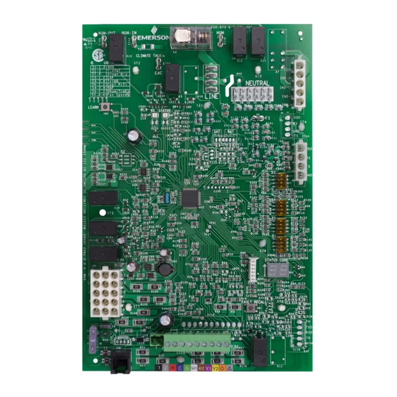
The 50C51-707 is a Two-Stage HSI Integrated Furnace
Control for Goodman Variable Speed blower applications. This
control is designed to work as part of a fully communicating
HVAC system using 4 wires or legacy 24 VAC inputs to
support non-communicating systems.
ELECTRICAL RATINGS:
Input Voltage:
24 VAC, 60 Hz (Class II transformer)
Current: 0
.8A @ 24 VAC
Relay Load Ratings:
Gas Valve Relays: 1.5 amp 0.6 PF @ 24 VAC
Ignitor Relay: 4.0 amp @ 120 VAC
Inducer Relay: 2.2 FLA – 3.5 LRA @ 120 VAC
Flame Current Requirements:
Min current to insure flame detection: 0.3 μA DC*
Max current for non-detection: 0.1 μA DC*
Max allowable leakage resistance: 100 M ohms
* Measured with a DC microammeter in series with the flame
probe lead
Operating Temperature Range:
-40° to 175°F (-40° to 80°C)
Humidity Range:
5 to 95% relative humidity (non-condensing)
Agency Approvals:
CSA USA / Canada
Gases Approved:
Natural, Manufactured, Mixed,
Liquid Petroleum, and LP Gas Air Mixtures.
Parts included:
• 50C51-707 Integrated Furnace Control
• Control Label
• Installation Instructions
white-rodgers.com
emerson.com
50C51-707
Two-Stage Integrated Furnace Control
for Furnace with Variable Speed Fan
INSTALLATION INSTRUCTIONS
CAUTION
!
Risk of Electric Shock.
Disconnect electric power
to system until installation
is complete. Do not use on
circuit exceeding specified
voltage. Higher voltage will
damage control and could
cause shock or fire hazard.
This control is not intended
for use in locations where
it may come in contact with
water.
May cause flame rollout.
Shut off main gas to heating
system until installation is
complete.
DESCRIPTION
SPECIFICATIONS
PART NO. 37-7668001
1712
Publicité
Table des Matières

Manuels Connexes pour Emerson White-Rodgers 50C51-707


Sommaire des Matières pour Emerson White-Rodgers 50C51-707
- Page 1 Shut off main gas to heating 5 to 95% relative humidity (non-condensing) system until installation is Agency Approvals: complete. CSA USA / Canada Gases Approved: Natural, Manufactured, Mixed, Liquid Petroleum, and LP Gas Air Mixtures. PART NO. 37-7668001 white-rodgers.com emerson.com 1712...
-
Page 2: Wiring Diagram
WIRING DIAGRAM... -
Page 3: Dipswitch Configuration
DIPSWITCH CONFIGURATION NOTE: • Cycle power after changes are made. • For best results set dip switches to prior boards configuration or refer to original OEM install manual for further details... -
Page 4: Heat Mode
OPERATION HEAT MODE Heating until Thermostat Output is Satisfied Blower Off Delay 15 s 17-19 s <5 s 30 s 15 s 90, *120, 150, 180 Thermostat - W2 Thermostat - W1 High Speed Inducer (IND HI) Low Speed Inducer (IND LO) Pressure Switch (PS2) Pressure Switch (PS1) Ignitor... -
Page 5: Cool Mode
OPERATION COOL MODE Output Cooling until Thermostat is Satisfied 5 sec 45 sec Thermostat - DEHUM Thermostat - Y2 Thermostat - Y1 Outdoor Compressor Outdoor Fan Blower (Cool Speed) Blower (High Heat Speed) Blower (Low Heat Speed) FAN MODE Output Fan until Thermostat is Satisfied Thermostat –... - Page 6 LED will be on to indicate faults are displayed a maximum of three times. return to normal status. TECHNICAL SUPPORT: 1-888-725-9797 Emerson and White-Rodgers are trademarks of Emerson Electric Co. white-rodgers.com ©2017 Emerson Electric Co. All emerson.com rights reserved.
-
Page 7: Spécifications
CSA/ACNOR É.-U. / Canada flamme. Coupez l’alimentation Gaz approuvés : Gaz naturel, manufacturé, mélangé, de gaz principale au système pétrole liquide et mélanges de GPL et air. de chauffage jusqu’à ce que l’installation soit terminée. DE PIÈCE 37-7668001 white-rodgers.com emerson.com 1712... -
Page 8: Schéma De Câblage
SCHÉMA DE CÂBLAGE Ligne d’alimentation *Pour thermostat sans de l’humidificateur ou *Pour thermostat avec humidification 24 V c.a. humidification Moteur de l’inducteur Apprentis- sage réseau DEL verte, réception DEL rouge comm. 120 V c.a. TRANSFORMATEUR 24 V C.A. CLASSE II 24 V c.a. -
Page 9: Configuration Des Commutateurs Dip
CONFIGURATION DES COMMUTATEURS DIP Type de thermostat/délai d’étage Délai d’arrêt du chauffage Délai d’arrêt Délai 90 s 120 s du chauffage d’arrêt du chauffage 1 ét. 2 ét.* Thermostat ARRÊT MARCHE ARRÊT MARCHE ARRÊT MARCHE ARRÊT MARCHE Délai d’arrêt Délai *150 s 180 s du chauffage... -
Page 10: Fonctionnement
FONCTIONNEMENT MODE CHAUFFAGE Chauffage jusqu’au Délai d’arrêt du Sortie réglage du thermostat souffleur 15 s 17-19 s <5 s 30 s 15 s 90, *120, 150, 180 Thermostat – W2 Thermostat – W1 Inducteur vitesse élevée (IND HI) Inducteur vitesse basse (IND LO) Pressostat (PS2) Pressostat (PS1) Allumeur... -
Page 11: Mode Climatisation
MENT FONCTIONNE MODE CLIMATISATION Sortie Climatisation jusqu’au réglage du thermostat 45 s Thermostat – Déshum. Thermostat – Y2 Thermostat – Y1 Compresseur extérieur Ventilateur extérieur Souffleur (vitesse de climatisation) Souffleur (vitesse de chauffage élevée) Souffleur (vitesse de chauffage lent) MODE VENTILATEUR Sortie Ventilateur jusqu’au réglage du thermostat Thermostat –... -
Page 12: Dépannage
Les pannes qui se répètent sont affichées au maximum trois fois. pour indiquer le retour au statut normal. SOUTIEN TECHNIQUE : 1-888-725-9797 Emerson et White-Rodgers sont des marques de commerce d’Emerson Electric Co. white-rodgers.com © 2017 Emerson Electric Co. Tous droits emerson.com réservés.