Antec PHANTOM 500 Manuel De L'utilisateur

Manuels Connexes pour Antec PHANTOM 500


Sommaire des Matières pour Antec PHANTOM 500
- Page 1 PHANTOM 500 User’s Manual Manuel de l’utilisateur Anwenderhandbuch Manuale per l’operatore Manual del usuario...
- Page 2 Table of Contents Table des matières / Inhaltsverzeichnis Índice / Indice English Français Deutsch Italiano Español Tables...
- Page 3 ATX power supplies include at least one fan that cools the power supply and helps expel heat from the chassis. Even though the Phantom 500 includes a fan, the fan will remain idle (to ensure silent operation) until the power supply's internal temperature exceeds a user-determined limit.
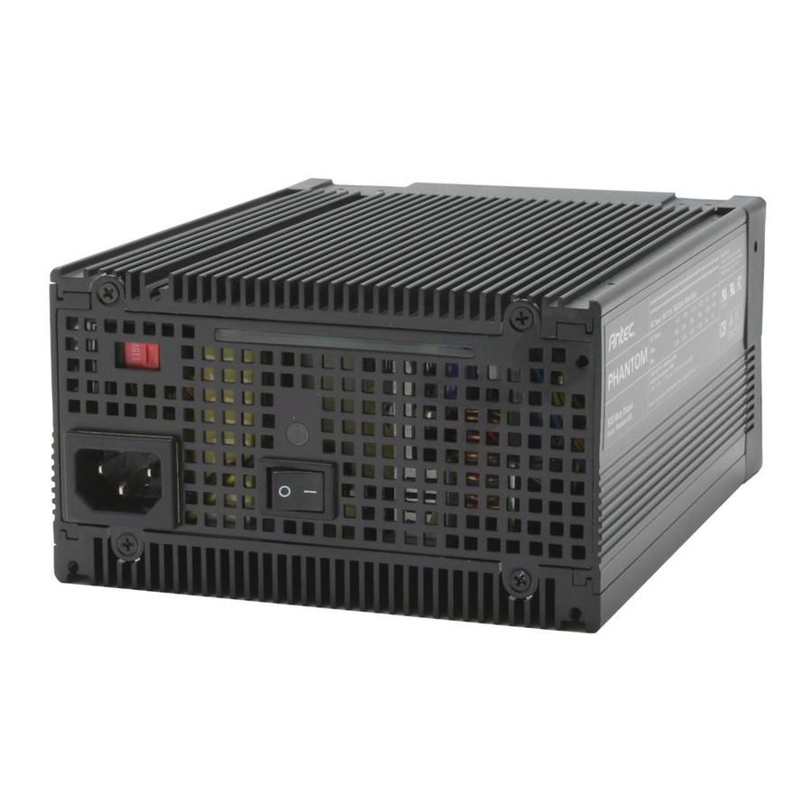
- Page 4 Power Switch: This power supply includes a main power switch. Make sure you turn the switch to the ON ( I ) position before you boot up your computer for the first time. In normal operation there is no need to turn the switch to the OFF ( O ) position since the power supply is equipped with a soft on/off feature which turns your computer on and off through the soft switch on your computer case.
- Page 5 Picture 2 Picture 1 For 24-pin For 20-pin motherboards motherboards 6. Set your desired fan operating mode. (See above for details.) 7. Close your computer case. 8. Connect the power cord to the Phantom 500.
- Page 6 Chez Antec, nous affinons et améliorons continuellement nos produits pour garantir une qualité supérieure. Il est donc possible que le nouveau Phantom 500 diffère sensiblement des descriptions contenues dans ce manuel. Il ne s'agit pas là d'un problème, juste d'une amélioration. A compter de la date de publication, toutes les fonctionnalités, descriptions et illustrations contenues dans ce manuel...
- Page 7 Phantom et transportez-le séparément. Interrupteur d'alimentation: Le Phantom 500 inclut un interrupteur d'alimentation secteur. Assurez-vous de mettre l'interrupteur sur position Marche ( I ) avant d'initialiser l'ordinateur pour la première fois. En cours de fonctionnement normal, inutile de mettre l'interrupteur sur position Arrêt ( O ) dans la mesure où...
- Page 8 Pour cartes mères à 24 mères à 20 broches broches 6. Définissez le mode de fonctionnement souhaité pour votre ventilateur. (Voir les détails ci-dessus). 7. Fermez le boîtier de votre ordinateur. 8. Branchez le cordon d'alimentation sur le Phantom 500.
- Page 9 Schutz vor Kurzschlüssen). Hinweis zur Gehäusebelüftung: Beachten Sie vor der Installation des Phantom 500 in Ihren PC Folgendes Ihr Gehäuse muss gut belüftet sein. Traditionelle ATX-Netzteile verfügen über mindestens einen Lüfter, der das Gerät kühlt und die Wärme vom Gehäuse wegführt. Zwar verfügt auch das Phantom 500 über einen Lüfter, allerdings bleibt dieser so lange inaktiv (und...
- Page 10 Transportempfehlung. Ihre Gehäusestruktur muss stabil genug sein, um das Netzteil tragen zu können. Das Phantom wiegt ca. 3kg, kann Ihr Gehäuse beim Transport also potenziell beschädigen. Wenn Sie Ihren PC transportieren möchten oder während des Transports einen rauen Umgang mit dem Paket befürchten, entfernen Sie das Netzteil und transportieren Sie es separat.
- Page 11 (natürlich ist dieser Modus nicht für diejenigen geeignet, die Ihren PC mit Overclocking betreiben oder viel spielen). Gehen Sie zur Installation Ihres Phantom 500 wie folgt vor: 1. Lösen Sie das Netzkabel von Ihrem alten Netzteil. 2. Öffnen Sie das Computergehäuse. Befolgen Sie hierbei die Anweisungen im Handbuch.
- Page 12 SCP (short circuit protection-protezione da cortocircuito). Nota per la ventilazione del telaio: Prima di installare Phantom 500 nel telaio del PC controllare quanto segue Il telaio del computer deve essere ventilato in modo appropriato. Gli alimentatori tradizionali ATX comprendono almeno una ventola che raffredda l'alimentatore e contribuisce ad espellere il calore dal telaio.
- Page 13 Raccomandazione di trasporto. La struttura del telaio deve essere abbastanza robusta da sostenere l'alimentatore. Phantom pesa ca.3 Kg, il che significa che può danneggiare il telaio, se si cerca di trasportare il computer per spedirlo. Se si programma di spedire il computer da qualche parte o se si prevedono manipolazioni poco accurate durante il trasporto, suggeriamo di rimuovere l'alimentatore Phantom e di eseguirne un trasporto separato.
- Page 14 Scheda madre con 24 pin con 20 pin 6. Impostare il modo operativo desiderato della ventola. (Vedere le istruzioni precedenti per eventuali dettagli in merito). 7. Chiudere il telaio del computer. 8. Collegare il cavo di alimentazione a Phantom 500.
- Page 15 UVP (protección contra tensión insuficiente) y SCP (protección contra cortocircuitos). Nota sobre la ventilación del chasis: Antes de instalar la Phantom 500 en el chasis del PC, tenga en cuenta lo siguiente El chasis debe tener buena ventilación. Las fuentes de alimentación ATX tradicionales cuentan al menos con un ventilador que las refrigera y contribuye a expulsar el calor del chasis.
- Page 16 Recomendación sobre transporte. La estructura del chasis debe ser capaz de resistir el peso de la fuente de alimentación. La unidad Phantom pesa aproximadamente 3kg, por lo que puede dañar el chasis si intenta transportar el ordenador con ella instalada. Si desea transportar el ordenador a otro punto, o si cree que la manipulación no será...
- Page 17 Placa madre Placa madre con 24 clavijas con 20 clavijas 6. Ajuste el modo de funcionamiento de ventilador que desee (consulte la información anterior). 7. Cierre la caja del ordenador. 8. Conecte el cable de alimentación a la Phantom 500.
- Page 18 1.0 INPUT / ENTRÉE / EINGANG / ALIMENTAZIONE IN INGRESSO / ENTRADA 1.1 VOLTAGE (AC Input) / TENSION (c.a.) / SPANNUNG (Wechselspannung) / TENSIONE (CA in ingresso) / TENSIÓN (entrada CA) RANGE / PLAGE / MINIMUM / NOMINAL / MAXIMUM / UNITS / UNITÉS / BEREICH / MIND.
- Page 19 OUTPUT / SORTIE / AUSGANG / USCITA / SALIDA VOLTAGE / TENSION / SPANNUNG +12V +12V +3.3V -12V +5Vsb TENSIONE / TENSIÓN MAX. LOAD / CHARGE MAX. / 0.8A 2.0A MAXIMALLAST / CARICO MAX. / CARGA MÁXIMA MIN. LOAD / CHARGE MIN. / 0.3A 0.3A 0.3A...
- Page 20 2.2 LOAD TRANSIENT RESPONSE (STEP LOAD) / RÉGIME TRANSITOIRE DE CHARGE / LASTÜBERGANGSVERHALTEN (SCHRITTLAST) / RISPOSTA ALLE VARIAZIONI DI CARICO (CARICO A GRADINO) / RESPUESTA A TRANSITORIOS DE CARGA (CARGA REPENTINA) Step load changes of up to 20% of full load, while other loads remains constant within the rating. The load waveform shall be a square wave with the slope of the rise and fall at 1A/us and the frequency shall be from 10Hz to 1 kHz.
- Page 21 3.0 PROTECTION / PROTECTION / SCHUTZSCHALTUNG / PROTEZIONE / PROTECCIÓN If the power supply is latched into shutdown stage (when OCP, OVP, OPP or short protection is working), the power supply shall return to normal operation only after the fault has been removed and should reset PS-ON for a minimum of 1 second.
-
Page 22: Over Current Protection / Protection Contre Les Surintensités
3.2 OVER CURRENT PROTECTION / PROTECTION CONTRE LES SURINTENSITÉS / SCHUTZ VOR STROMSPITZEN / PROTEZIONE DA SOVRACORRENTI / PROTECCIÓN CONTRA SOBRECORRIENTE SENSE LEVEL / NIVEAU DE DÉTECTION / OVER CURRENT / SURINTENSITÉ / ABFÜHLPEGEL / LIVELLO DI PERCEZIONE STROMSPITZEN / SOVRACORRENTE / NIVEL DE DETECCIÓN SOBRECORRIENTE 18.7A min. - Page 23 3.6 OVER TEMPERATURE / SURCHAUFFE / ÜBERHITZUNGSSCHUTZ / SOVRATEMPERATURA / PROTECCIÓN CONTRA LA TEMPERATURA EXCESVA The power supply includes an over-temperature protection sensor, which can trip and shutdown the power supply at 100°C. Such an overheated condition is typically the result of internal current overloading or a cooling fan failure Le bloc d'alimentation inclut un capteur de protection anti-surchauffe, qui bascule et arrête le bloc d'alimentation à...
- Page 24 4.0 TIME SEQUENCE / SÉQUENCE CHRONOLOGIQUE / ZEITLICHE ABFOLGE / SEQUENZA DI TEMPO / SECUENCIA DE TIEMPO Power-On Time / Temps de mise sous tension / Einschaltdauer / (500ms.max.) Tempo di accensione / Tiempo de encendido Rise-time / Temps de montée / Anlaufzeit / Tempo di salita / (20ms.max.) Tiempo de elevación Power Good Delay Time / Délai de mise sous tension correcte /...
- Page 25 115V/230V (PLEINE CHARGE) : 1ms minimum FIGURE 1 115V/230V (MAXIMALLAST): 1ms mind ABBILDUNG 1...
- Page 26 115V/230V (PIENO CARICO): 1ms minimo FIGURA 1 115 V/230V (PLENA CARGA): 1ms mínimo FIGURA 1...
- Page 27 4.1 REMOTE ON/OFF CONTROL / TÉLÉCOMMANDE / FERNSTEUERUNG DER EIN-/AUSSCHALTUNG / TELECOMANDO DI ACCENSIONE / SPEGNIMENTO (ON/OFF) / CONTROL DE ENCENDIDO/APAGADO A DISTANCIA The power supply is turn on / off by TTL signal / Le bloc d'alimentation est mis sous / hors tension par un signal TTL / Das Netzteil wird per TTL-Signal ein-und ausgeschaltet / L'alimentatore è...
- Page 28 4.2 AUXILIARY +5Vsb / AUX (+5 Vsb) / AUXILIAIRE +5Vsb / AUSILIARIO +5Vsb / AUXILIAR +5Vsb This power supply is specifically equipped with an independent stand-by +5V output current, 2.0A max. This output will always provide +5V except when the AC line is cut-off Ce bloc d'alimentation est spécialement équipé...
- Page 29 5.0 ENVIRONMENT / ENVIRONNEMENT / UMGEBUNGSBEDINGUNGEN / AMBIENTE / CONDICIONES AMBIENTALES 5.1 AMBIENT OPERATION TEMPERATURE / TEMPÉRATURE 0ºC to +50ºC / 0 à D'EXPLOITATION AMBIANTE / UMGEBUNGSTEMPERATUR +50ºC / 0ºC bis +50 (BETRIEB) / TEMPERATURA AMBIENTALE DI FUNZIONAMENTO / ºC / da 0ºC a +50°C / TEMPERATURA DE FUNCIONAMIENTO De 0°C a +50°C 5.2 AMBIENT OPERATION RELATIVE HUMIDITY / HUMIDITÉ...
- Page 30 8.0 DC CONNECTOR AND CASE REQUIREMENTS / CONNECTEURS C.C. ET BOÎTIER EXIGÉ / ANFORDERUNGEN FÜR GLEICHSTROMANSCHLUSS UND GEHÄUSE / REQUISITI DEL CONNETTORE CC E DEL TELAIO / REQUISITOS DEL CONECTOR CC Y DE LA CAJA 8.1 BASEBOARD CONNECTEUR DE GRUNDPLATTE- CONNETTORE CONECTOR DE CONNECTOR...
- Page 31 PERIPHERAL CONNECTOR / CONNECTEUR DE FLOPPY DRIVE CONNECTOR / CONNECTEUR PÉRIPHÉRIQUE / ANSCHLUSS FÜR PERIPHERIE DE LECTEUR DE DISQUETTE / ANSCHLUSS DISKETTENLAUFWERK / CONNETTORE FÜR / CONNETTORE PER UNITÀ FLOPPY / PERIFERICO / CONECTOR PARA PERIFÉRICOS CONECTOR PARA UNIDAD DE DISQUETES HOUSING: JMT JP1120-4 / BOÎTIER: JMT HOUSING: JMT JP11635-4 / BOÎTIER:...
- Page 32 4pin +12V POWER CONNECTOR / CONNECTEUR D’ALIMENTATION +12 V / +12-V-NETZANSCHLUSS / CONNETTORE DI ALIMENTAZIONE +12V / CONECTOR DE CORRIENTE +12 V HOUSING: MOLEX 39-01-2040 or equivalent / BOÎTIER: MOLEX 39-01-2040 ou équivalent / GEHÄUSE: MOLEX 39-01-2040 oder Äquivalent / ALLOGGIAMENTO: MOLEX 39-01-2040 o equivalente / CARCASA: MOLEX 39-01-2040 o equivalente TERMINAL: MOLEX 39-29-9042 or equivalent / BORNE: MOLEX 39-29-9042 ou équivalent / KLEMME: MOLEX 39-29-9042 oder Äquivalent / TERMINALE: MOLEX 39-29-9042 o equivalente /...
- Page 33 SERIAL ATA POWER CONNECTOR / CONNECTEUR D’ALIMENTATION ATA SÉRIE / SATA-NETZANSCHLUSS / CONNETTORE DI ALIMENTAZIONE SERIAL ATA / CONECTOR DE CORRIENTE SERIAL ATA HOUSING: MOLEX 675820000 OR EQU / BOÎTIER: MOLEX 675820000 OU ÉQUIVALENT / GEHÄUSE: MOLEX 675820000 ODER ÄQUIVALENT / ALLOGGIAMENTO: MOLEX 675820000 O EQUIV / CARCASA: MOLEX 675820000 O EQUIV TERMINAL: MOLEX 67581000 OR EQU / BORNE: MOLEX 67581000 OU ÉQUIVALENT / KLEMME: MOLEX 67581000 ODER ÄQUIVALENT / TERMINALE: MOLEX 67581000 O EQUIV /...
- Page 34 +31 (0) 10 462-2060 europe.techsupport@antec.com www.antec.com © Copyright 2005 Antec, Inc. All rights reserved. All trademarks are the property of their respective owners. Reproduction in whole or in part without written permission is prohibited. Printed in China. Version 1.0.5 1/28/2005...