Table des Matières
Publicité
Les langues disponibles
Les langues disponibles
Liens rapides
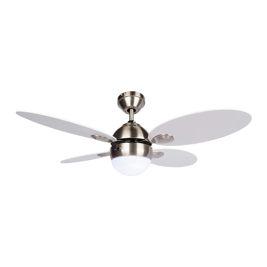
Scandinavian 42" Ceiling Fan
model no. 052-9335-6
Total weight of fan plus light kit are 6.5 kgs
Instruction Manual
Toll-free: 1-866-827-4985
IMPORTANT: Please read and understand this manual before any assembly
Before beginning assembly of product, make sure all parts are present.
Compare parts with exploded view. If any part is missing, or if you have any
q
u
e
t s
o i
n
, s
c
o
n
a t
t c
c
u
t s
o
m
r e
s
e
v r
c i
e
t a
1
8 -
6
6
8 -
2
- 7
4
9
8
5
t (
.
l o
f - l
e r
e
. )
Publicité
Table des Matières

Manuels Connexes pour NOMA Scandinavian 052-9335-6


Sommaire des Matières pour NOMA Scandinavian 052-9335-6
- Page 1 Scandinavian 42" Ceiling Fan model no. 052-9335-6 Total weight of fan plus light kit are 6.5 kgs Instruction Manual Toll-free: 1-866-827-4985 IMPORTANT: Please read and understand this manual before any assembly Before beginning assembly of product, make sure all parts are present. Compare parts with exploded view.
- Page 2 Table of Contents Technical Data Important Safety Instructions Parts List Parts Locations Before Installation Installation Operation Care and Maintenance Troubleshooting Warranty Operating voltage: 120 V/60 Hz Power consumption: Fan only: 45 W (Maximum) Bulbs: One A19 11W(Max) LED bulb (included)
- Page 3 WARNING! or circuit breaker box before installing, servicing or cleaning. DO NOT use the ceiling fan if it shows any sign of damage or if it has been dropped. DO NOT expose the ceiling fan to rain or moisture. Do not operate it outdoors or with wet hands. DO NOT operate the fan without blades.
- Page 4 ree: 1-866-827-4985 · model nos. 052-9335-6 Toll-f Name Illustration Qty. Name Illustration Qty. Blade Mounting Decoration Bracket Remote Control Canopy Wood Screw with Flat Washer Blade Screw Receiver with flat washer Extra Blade Downrod Bracket Screw Assembly with spring washer Mouting Screw with Split Washer...
- Page 5 Description Description Blade Arm Mounting Bracket Blade Decoration R eceiver Canopy Remote Control Motor Housing Parts Pack Balance Pack Blade Bulb (A19 X 11 W LED)
- Page 6 -827-4985 · model nos. 052-9335-6 Toll-free : 1-866 WARNING! Read each step carefully before beginning any installation and make sure you understand each step. Keep children and pets away during installation. Keep fingers away from the places where they can be pinched or injured. Tools Needed for Assembly (not supplied): 1 cross-head 1 stepladder...
- Page 7 Choosing a Location for the Ceiling Fan Choose a location where there is a high enough ceiling clearance, at least 6’ 11” (2.1 m) between the floor and the blades (fig. 3). located in the centre of the room, or a minimum of 32”...
- Page 8 Toll-free: 1-866-827-4985 · model nos. 052-9335-6 1. Installing Mounting Bracket Remove the four sets of side screws from mounting bracket and save for future use (fig. 6). Attach the mounting bracket to the normal masonry ceiling or wooden ceiling as indicated below. Normal masonry ceiling Wooden ceiling Drill two mounting holes in the ceiling joist.
-
Page 9: Canopy Assembly
2.2 Canopy Assembly Remove three of the six screws and lock washers (every other one) securing the motor collar to the Screw top of the fan motor housing (fig. 10). Guide all the wires through the base of the canopy Canopy (fig. - Page 10 Toll-free: 1-866-827-4985 · model nos. 052-9335-6 3.3 Securing Downrod Assembly Raise the canopy. Clip Screw Loosen the two downrod set screws on the coupling (fig. 14). Insert the downrod into the coupling. Make sure to align the holes of these two parts. Install the peaked pin through the aligned holes and Peaked secure it with the clip.
-
Page 11: Making Connections
Installing Receiver Assembly Once the connection has been made, the receiver inserts into the drop rod hanging bracket. The canopy comes up to cover the receiver and bracket.(fig. 16). 4.2 Making Connections Between fan and receiver: · Connect the black wire marked “L” from the fan to the black wire marked “TO MOTOR L” from the receiver. - Page 12 Toll-free: 1-866-827-4985 · model nos. 052-9335-6 While connecting wires, make sure to: Match up the wires first. Hold the bare metal leads together and twist until tight. Insert the twisted ends into a wire connector and turn the wire connector until tight (fig. 18). After all connections are done, turn the splices upward and push them carefully upward through the mouting bracket into the outlet box.
- Page 13 6. Blade Assembly to Motor Remove all the blade bracket screws with split washers from the motor bottom, through the oval slot on the light kit assembly (fig.21). Light kit Attach one blade assembly to the motor bottom and secure with the blade bracket screws and split washers (fig.22).
- Page 14 Toll-free: 1-866-827-4985 · model nos. 052-9335-6 turn clockwise till tight light (fig. 24). Now your ceiling fan is assembled and ready for use. Glass shade Install the battery cover from the back of the remote transmitter and insert 2AA (fig. a) or 9V batteries (fig.
- Page 15 Changing Air-flow Direction complete stop. Slide the reverse switch on the light kit. Reverse switch Side Description Left Downward air-flow (Forward) Right Upward air-flow (Reverse) Restart the fan. Balancing Kit This balancing kit should be used only if there is an unacceptable amount of fan wobble after all installations are correctly completed (fig.
- Page 16 Toll-free: 1-866-827-4985 · model nos. 052-9335-6 Warning! or circuit breaker box before installing, servicing or cleaning. Never clean the fan while in use! Because of the fan’s natural movement, some connections may become loose. Check the support connections, brackets and blade attachments regularly. Make sure they are secure. There is no need to oil your fan.
-
Page 17: Environmental Protection
Problem Possible reason Solution Wires are not properly connected. Ensure wire connector in the switch housing is connected. Light bulb is faulty. Remove light bulb and replace with a new one of the same type. Light does This fan is equipped with a 70 W not work LIMITER that will automatically turn with lower wattage bulbs so that the... - Page 18 Toll-free: 1-866-827-4985 · model nos. 052-9335-6 This Noma product carries a limited one (1) year warranty against defects in workmanship and materials. Noma Canada agrees to replace the defective product free of charge within the stated warranty period, when returned by the original purchaser with proof of purchase. This product is not guaranteed against wear or breakage due to misuse and/or abuse.
-
Page 19: Ventilateur De Plafond De 42 Po Scandinavian
Ventilateur de plafond de 42 po Scandinavian N° de modèle : 052-9335-6 Poids total du ventilateur et de l'ensemble éclairage est de 6,5 kg Manuel d'utilisation Sans frais : 1 866 827-4985 IMPORTANT : Veuillez lire ce guide et bien le comprendre avant de commencer l’assemblage. - Page 20 Table des matières Caractéristiques techniques Consignes de sécurité importantes Liste des pièces Emplacement de pièces Avant l’installation Installation Utilisation Entretien Dépannage Garantie Tension opérationnelle : 120 V/60 Hz Consommation d’énergie : Ventilateur seulement : 45 W (maximum) Ampoules : Une ampoule à DEL A19 11 W (maximum) (comprise)
- Page 21 AVERTISSEMENT! Afin d’éviter les décharges électriques, éteignez le courant au fusible principal ou au co ret de fusibles avant l’installation, la réparation ou le nettoyage. NE PAS utiliser le ventilateur de plafond s’il montre des signes de dommages ou s’il a été échappé. NE PAS exposer le ventilateur de plafond à...
- Page 22 Sans frais : 1 866 827-4985 . Modèle no 052-9335-6 Illustration Qté Illustration Qté Décoration Support de pale de fixation Télécommande Toit Vis à bois avec rondelle plate Vis de pale Récepteur avec rondelle plate Vis additionnelle Assemblage pour support de la tige de pale avec rondelle à...
- Page 23 Description Qté Description Qté Bras de pale Support de fixation Décoration de pale Tige Récepteur Toit Télécommandes Boîtier de moteur Paquet de pièces Ensemble d’éclairage Paquet d’équilibrage Abat-jour en verre Pale Ampoule (DEL A19 X 11 W)
- Page 24 Sans frais : 1 866 827-4985 . Modèle no 052-9335-6 AVERTISSEMENT! Lisez attentivement toutes les étapes et assurez-vous de bien les comprendre avant de commencer l’installation. Tenez les enfants et les animaux domestiques à distance pendant l’installation. Évitez de mettre vos doigts là où ils pourraient se coincer ou être blessés. Outil requis pour l’assemblage (non fournis) : 1 tournevis 1 escabeau...
- Page 25 Choisir un emplacement pour le ventilateur de plafond Choisissez un emplacement où il y a un plafond haut, au moins 2,1 m ou 6 pi 11 po entre le sol et les pales (figure 3). Plafond Pour une circulation de l’air e cace, le ventilateur doit être situé...
-
Page 26: Assemblage Des Pales
Sans frais : 1 866 827-4985 . Modèle no 052-9335-6 1. Installation du support de montage Retirez les quatre séries de vis de pression du support de montage et gardez-les pour une utilisation future (figure 6). Fixez le support de montage au plafond en bois ou au plafond de maçonnerie ordinaire comme indiqué... -
Page 27: Assemblage Du Boîtier
2.2 Assemblage du boîtier Retirez trois des six vis et rondelles de sécurité (chaque deux vis) qui maintiennent le collier du moteur sur le haut du ventilateur (figure 10). Passez tous les câbles à travers la base du boîtier Toit (figure 10). -
Page 28: Fixation De L'assemblage De La Tige
Sans frais : 1 866 827-4985 . Modèle no 052-9335-6 3.3 Fixation de l’assemblage de la tige Levez le boîtier. Desserrez les deux vis de pression de la tige sur Fixation le raccord (figure 14). Insérez la tige dans le raccord. Assurez-vous d’aligner les trous de ces deux pièces. -
Page 29: Procéder Au Branchement
Installation du récepteur Une fois la connexion e ectuée, le récepteur s’insère dans le support de suspension de la tige. Le boîtier vient couvrir le récepteur et le support. (Figure 16) Laissez déconnecté et ne pas couper. APRÈS L’INSTALLATION 4.2 Procéder au branchement Entre le ventilateur et le récepteur : ·... - Page 30 Sans frais : 1 866 827-4985 . Modèle no 052-9335-6 En reliant les fils, assurez-vous de : Associez les fils en premier. Maintenez le plomb en métal nu ensemble et serrez-le en tournant. Insérez les extrémités torsadées dans un connecteur de fils et serrez le connecteur en le tournant (figure 18).
- Page 31 6. Fixer les pales au moteur Retirez toutes les vis avec rondelles fendues du support de pale sur la partie inférieure du moteur, par la fente ovale de l’ensemble Fente ovale d’éclairage (figure 21). Ensemble d’éclairage Installez l’un des ensembles de pales au bas du moteur et fixez-le avec les vis et les rondelles fendues du support de pale Vis de...
- Page 32 Sans frais : 1 866 827-4985 . Modèle no 052-9335-6 8. Installer l’abat-jour en verre Installez l’abat-jour en verre à l’ensemble d’éclairage et tournez dans le sens horaire jusqu’à qu’il soit serré (figure 24). Votre ventilateur de plafond est maintenant assemblé...
- Page 33 Changer l’orientation de la circulation d’air Éteignez le ventilateur et laissez-le s’arrêter complètement. Faites glisser l’interrupteur d’inversion de l’ensemble d’éclairage. Interrupteur de marche arrière Côté Description Gauche Circulation d’air vers le bas (avant) Circulation d’air vers le haut (arrière) Droit Redémarrez le ventilateur.
-
Page 34: Nettoyage
Sans frais : 1 866 827-4985 . Modèle no 052-9335-6 Avertissement! Afin d’éviter les décharges électriques, éteignez le courant au fusible principal ou au co ret de fusibles avant l’installation, la réparation ou le nettoyage. Ne jamais nettoyer le ventilateur durant l’utilisation. En raison du mouvement naturel du ventilateur, certaines connexions peuvent devenir lâches. -
Page 35: Protection De L'environnement
Solution Problème Cause possible Les fils ne sont pas correctement Assurez-vous que le connecteur de fils connectés. dans le boîtier de l’interrupteur est connecté. L’ampoule est défectueuse. Retirez l’ampoule et remplacez-la par une autre du même type. La lumière ne Ce ventilateur est équipé... -
Page 36: Garantie
Sans frais : 1 866 827-4985 . Modèle no 052-9335-6 Garantie Cet article Noma comprend une garantie de un (1) an contre les défauts de fabrication et de matériaux. Noma Canada consent à remplacer l’article défectueux sans frais au cours de la période de garantie convenue lorsque l’article, accompagné...