AEG RC 3.5 Notice D'utilisation
Table des Matières
Les langues disponibles
Les langues disponibles
Liens rapides
D
RÜCKFAHRKAMERA-SYSTEM RV 3.5
GB REAR CAMERA SYSTEM RV 3.5
F
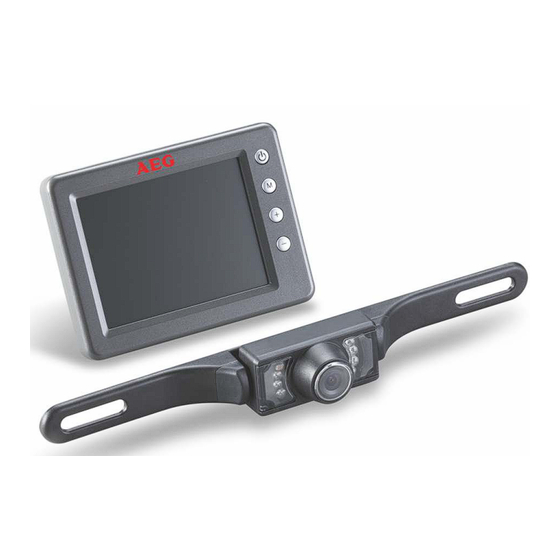
SYSTÈME DE CAMÉRA DE RECUL RV 3.5
I
SISTEMA TELECAMERA PER RETROMARCIA RV 3.5
CZ SYSTÉM COUVACÍ KAMERY RV 3.5
SK CÚVACÍ KAMEROVÝ SYSTÉM RV 3.5
KAMERA-SYSTEM
RÜCKFAHR-
BEDIENUNGSANLEITUNG
OPERATING INSTRUCTIONS 15
NOTICE D'UTILISATION
ISTRUZIONI PER L'USO
NÁVOD NA POUŽITIE
NÁVOD K POUŽITÍ
RV 3.5
02
28
41
54
67
Chapitres
Table des Matières

Manuels Connexes pour AEG RC 3.5

Sommaire des Matières pour AEG RC 3.5
- Page 1 RÜCKFAHRKAMERA-SYSTEM RV 3.5 BEDIENUNGSANLEITUNG GB REAR CAMERA SYSTEM RV 3.5 OPERATING INSTRUCTIONS 15 SYSTÈME DE CAMÉRA DE RECUL RV 3.5 NOTICE D'UTILISATION SISTEMA TELECAMERA PER RETROMARCIA RV 3.5 ISTRUZIONI PER L'USO CZ SYSTÉM COUVACÍ KAMERY RV 3.5 NÁVOD NA POUŽITIE SK CÚVACÍ...
- Page 28 SOMMAIRE 1.0 INTRODUCTION 1.1 Que signifient les symboles ? 1.2 Fonctionnement du système de caméra de recul 1.3 Utilisation conforme 1.4 Caractéristiques du système de caméra de recul 2.0 CONSIGNES DE SÉCURITÉ 2.1 Consignes générales de sécurité 2.2 Consignes de sécurité pour le montage du système de caméra de recul 3.0 DESCRIPTION DU PRODUIT 3.1 Contenu de l'emballage 3.2 Détail du produit...
-
Page 29: Introduction
1.2 Fonctionnement du système de caméra 1.0 INTRODUCTION de recul Chère cliente, Le système de caméra de recul RV 3.5 sert à une Cher client, meilleure visibilité lorsque l'on roule en marche arrière, par ex. pour se garer. En appuyant sur le Nous vous félicitons pour l'achat de votre nouvelle bouton Marche / Arrêt, l'écran couleur s'allume et "caméra de recul RV 3.5"... -
Page 30: Caractéristiques Du Système De Caméra De Recul
2.1.1 Maintenez le système de caméra 1.4 Caractéristiques du système de de recul éloigné des enfants ! Les en- caméra de recul fants ne comprennent pas ou ne recon- ▪ Permet une meilleure visibilité derrière le naissent pas les dangers possibles liés aux appa- véhicule, pour une plus grande sécurité... -
Page 31: Consignes De Sécurité Pour Le Montage Du Système De Caméra De Recul
2.1.10 Toutes les réparations sur le système 2.1.22 Si de la lumière forte se projette directe- doivent être effectuées par un électricien / un ment sur la lentille de la caméra, les objets technicien spécialisé. peuvent être surexposés et ne pas être affichés 2.1.11 Le système de caméra de recul ne doit clairement. -
Page 32: Description Du Produit
2.2.7 Lors du montage, veillez à ce que les câb- 2.2.16 Pendant le montage du système, ne portez les soient placés de façon sûre et solide. Ne les aucun bijou métallique. Cela pourrait entraîner installez pas contre des matériaux conducteurs. Si un court-circuit ou des brûlures ! les câbles sont placés dans des parois coupantes 2.2.17 Placez le câble de sorte qu'on ne puisse... -
Page 33: Détail Du Produit
3.2 Détail du produit 4.0 MONTAGE / UTILISATION 4.1 Montage du système de caméra de recul Attention ! En raison des différents types de véhicules à la technologie et la structure variées, la présente notice de montage n'est pas valable pour tous les véhicules. - Page 34 Clipsez ensuite le joint en plastique sur le côté Vous pouvez étanchéifier le joint en plastique extérieur du point de perçage sur le véhicule. en appliquant un mastic classique des deux côtés pour empêcher que l'eau ne rentre. Etape 3 : Fixer les supports de la caméra Montez les deux supports de la caméra et, si nécessaire, le support de la plaque d'immatricula-...
- Page 35 Étape 7 : Connecter le câble d'alimentation Insérez le câble plus 12 avec l'émetteur V + des feux de recul sur Retirez le cache des feux de recul. Retirez le le côté du connecteur à support de l'ampoule du carter. Recherchez les pince (voir image 8).
-
Page 36: Étape 9 : Contrôler L'alimentation Électrique De L'émetteur
4.2 Montage de l'écran Étape 8 : Fixer l'émetteur Fixez l'émetteur avec du matériel de fixation ▪ Insérez le logement rectangulaire du bras de approprié, p. ex. deux attache-câbles. Veillez à l'écran dans l'ouverture située à l'arrière de ce qu'aucun consommateur électrique ne se trouve l'écran. -
Page 37: Utilisation De L'écran
4.3 Utilisation de l'écran ▪ Avec les touches ( + ) et ( - ) , vous pouvez augmenter, réduire ou activer les para- mètres suivants : Clarté : Régler la clarté de l'écran Contraste : Régler le contraste de l'écran Couleur : Régler l'intensité... -
Page 38: Recherche D'erreurs
4.7 Recherche d'erreurs Erreur / Dysfonction- Causes possibles Solutions, aide nement Le véhicule est démarré et l'écran La prise 12 V du câble de l'écran Branchez la prise 12 V du câble est allumé, la marche arrière est n'a pas été branchée à l'allume- de l'écran dans l'allume-cigare enclenchée mais l'écran reste cigare ou à... -
Page 39: Maintenance Et Entretien
5.0 MAINTENANCE ET 6.0 CARACTÉRISTIQUES ENTRETIEN TECHNIQUES 5.1 Nettoyage, maintenance et Désignation de l'article : Système de caméra de entretien recul RV 3.5 Référence : 97152 Température de service - 10 C à + 50 C ° ° et de travail : (Celsius) Vitesse de marche max. -
Page 40: Élimination
8.0 SERVICE L'appareil est conforme aux directives CE suivantes : ▪ Directive de télécom- Si après avoir lu soigneusement le présent mode munication 1999/5/ d'emploi vous avez encore des questions concernant la mise en service ou l’utilisation ou si ▪ Directive sur la comp- un problème venait à...