Thermaltake Core V71 Mode D'emploi
Table des Matières
Liens rapides
© 2015 Thermaltake Technology Co., Ltd. All Rights Reserved. B-2015.01
All other registered trademarks belong to their respective companies.
Tested To Comply
With FCC Standards
FOR HOME OR OFFICE USE
www.thermaltake.com
C
V71
ore
Your Build. Our Core
User's Manual
Benutzerhandbuch
Mode d'emploi
Manual del usuario
Manuale dell'utente
Manual do Utilizador
安裝說明書
用戶手冊
ユーザーズマニュアル
Руководство пользователя
kullanıcı elkitabı
(EEE Yönetmeliğine Uygundur)
คู ่ ม ื อ การใช้
www.thermaltake.com
Table des Matières

Manuels Connexes pour Thermaltake Core V71


Sommaire des Matières pour Thermaltake Core V71
- Page 1 ユーザーズマニュアル Руководство пользователя kullanıcı elkitabı (EEE Yönetmeliğine Uygundur) คู ่ ม ื อ การใช้ © 2015 Thermaltake Technology Co., Ltd. All Rights Reserved. B-2015.01 All other registered trademarks belong to their respective companies. www.thermaltake.com Tested To Comply With FCC Standards FOR HOME OR OFFICE USE www.thermaltake.com...
- Page 2 LCS chassis should be held to. The Tt LCS certification was created so that we at Thermaltake can designate to all power users which chassis have been tested to be best compatible with extreme liquid cooling configurations to ensure you get the best performance from the best features and fitment.
-
Page 3: Table Des Matières
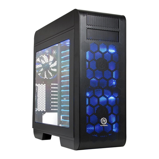
Specification Case Type Full Tower Dimension (H*W*D) 583 x 230 x 560 mm (23 x 9.1 x 22 inch) Side Panel Transparent Window Contents Material SPCC Front (intake) : 200 x 200 x 30 mm Blue LED fan x 2 (600~800rpm, 13~15dBA) Chapter 1. -
Page 4: Warning And Notice
Warning and Notice Atenção!! Limite de altura para o dissipador do CPU: O limite de altura para o dissipador do CPU é 185 mm (7,3 polegadas). Limite de comprimento para VGA (placa gráfica): O limite de comprimento para VGA (placa gráfica) é 310 mm (12.2 polegadas). 警告!!... -
Page 5: Side Panels Disassembly
Power Supply Unit (PSU) Installation Side Panels Disassembly Español / 1. Instale la PSU en la ubicación correcta. 2. Ajuste el puente de soporte de la PSU en la ubicación adecuada y asegúrela con tornillos. Italiano / 1. Posizionare la PSU in modo corretto. 2. -
Page 6: Motherboard Installation
Motherboard Installation 5.25" Device Installation English / 1. Pull out the front panel. 2. Remove the 5.25” drive bay cover. 3. Insert the 5.25” device and tighten it with the screws. 4. Slide the 5.25” device into the drive bay to lock the device. -
Page 7: 2.5" Hdd Installation
3.5" & 2.5" HDD Installation Type A Português/ Türkçe / 1. Puxe o painel dianteiro para fora. 1. Ön paneli çekerek çıkarın. 2. Remova a cobertura da baía da unidade de 5,25". 2. 5,25" sürücü bölmesi kapağını çıkarın. 3. Insira o dispositivo de 5,25" e aparafuse. 3. -
Page 8: Hdd Cage Installation
HDD Cage Installation English / 繁體中文 / 1.Press a latch to pull the tray out. 1. 輕壓硬碟托盤左側開啟硬碟托盤,並向外拉出 2. Remove the locking clips then position the HDD 硬碟托盤。 Type A Type B Type C in the tray and secure the HDD with the locking 2. -
Page 9: Pci Card Installation
PCI Card Installation Keyboard & Mouse Security Lock Usage English / 繁體中文 / Place the keyboard or mouse cables through the 將鍵盤或滑鼠纜線穿過「鍵盤和滑鼠安全鎖」,然後用 “Keyboard & Mouse Security Lock” then secure it 螺絲將其固定回機殼內的背板。 back to the back panel from inside of the chassis English / 繁體中文... -
Page 10: Fan Speed & Light Control Operation
Fan Speed & Light Control Operation Fan Speed & Light Controller Connector Descriptions ① 4-pin peripheral connector ②,③,④ Fan power & signal connector (Front & Top) WARNING! Fan speed and light controller are only compatible with built in 200mm LED fans. To avoid on damaging the circuit board, please do not connect it with other fans. -
Page 11: Air Cooling Installation
Air Cooling Installation Top 20cm Fan Installation Notice 1. Remove the I/O bracket first 2. Install the 20cm fan with screws 12cm x 3 14cm x 2 20cm x 2 Rear 14cm x 1 20cm x 2 Front 14cm x 2 12cm x 1 12cm x 3 Bottom Fan... -
Page 12: Liquid Cooling Installation
Liquid Cooling Installation Maximum Radiator Installation Notice 20cm Fan 42cm Radiator 36cm x 1 42cm x 1 Rear 12cm x 1 42cm x 1 Front 36cm Radiator 36cm x 1 20cm Fan 24cm x 1 12cm x 1 Bottom... -
Page 13: Filter Installation
Filter Installation Leads Installation English Leads Installation Guide Case LED Connection / On the front of the case, you can find some LEDs and switch leads. Please consult your user manual of your motherboard manufacturer, then connect these leads to the panel header on the motherboard. USB 2.0 Connection / Please consult your motherboard manual to find out the section of “USB connection”. - Page 14 Français Italiano Guide d'installation des fils Guida di installazione dei contatti Connexion des voyants du boîtier / Sur la face avant du boîtier, vous trouverez plusieurs voyants et les fils des Connessione del LED del case / Nella parte anteriore del case, sono presenti alcuni contatti per interruttori e LED. boutons.
- Page 15 繁體中文 日 本 語 線材安裝說明 リード線の取り付けガイド 機殼LED連接方式 / 在機殼前方的面板後面,可以找到一些LED與開關線材(POWER Switch….),請參考主機板使用說明書, ケース LED の接続 / ケース前面には、LEDとスイッチリード線があります。 マザーボードメーカーのユーザーマニュアル 並將機殼上的線材正確地連接到主機板上,這些線材通常都會印有標籤在上面,如果沒有的話,請找出機殼前方面板上線材原 を参照し、これらのリード線をマザーボードのパネルヘッダに接続してください。 本的位置以知道正確的來源。 USB 2.0 の接続 / マザーボードのマニュアルを参照して、「USB接続」のセクションを探します。 USB 2.0 連接 / 請參考主機板使用手冊找出主機板上的USB連接孔位 USB 3.0 の接続 / USB 3.0 連接 / 1. お使いのマザーボードがUSB 3.0接続をサポートしていることを確認してください。 1.
- Page 16 Türkçe Ara Kablo Kurulum Kılavuzu Kasa ışık bağlantısı / Kasanın ön kısmında bazı ışıklar ve anahtar ara kabloları görebilirsiniz. Lütfen anakart üreticinizin sağladığı kullanım kılavuzuna bakın ve daha sonra, bu ara kabloları, anakart üzerindeki panel bağlantı noktalarına bağlayın. USB 2.0 bağlantısı / Lütfen anakart kılavuzunuzun “USB bağlantısı” bölümüne bakın. USB 3.0 Bağlantısı...