Masquer les pouces Voir aussi pour P-Series:
Table des Matières

Publicité

Les langues disponibles

Les langues disponibles

Liens rapides

BEDIENUNGSANLEITUNG
USER'S MANUAL
MODE D'EMPLOI
P-SERIES
Professional amplifiers
©
Für weiteren Gebrauch aufbewahren!
Copyright
Keep this manual for future needs!
Nachdruck verboten!
Gardez ce mode d'emploi pour des
Reproduction prohibited!
utilisations ultérieures!
Réproduction interdit!

Publicité

Table des Matières
loading

Sommaire des Matières pour Omnitronic P-Series

  • Page 1 BEDIENUNGSANLEITUNG USER'S MANUAL MODE D'EMPLOI P-SERIES Professional amplifiers © Für weiteren Gebrauch aufbewahren! Copyright Keep this manual for future needs! Nachdruck verboten! Gardez ce mode d’emploi pour des Reproduction prohibited! utilisations ultérieures! Réproduction interdit!
  • Page 3: Table Des Matières

    MULTI-LANGUAGE-INSTRUCTIONS Inhaltsverzeichnis Table of contents Sommaire EINFÜHRUNG..............................5 Features ................................. 5 SICHERHEITSHINWEISE..........................5 BESTIMMUNGSGEMÄSSE VERWENDUNG ....................7 GERÄTEÜBERSICHT............................8 Frontplatte ..............................8 Rückseite ............................... 9 RECHTLICHE HINWEISE..........................10 Kleine Hörkunde............................10 INSTALLATION .............................. 11 Rackinstallation ............................11 Eingänge ..............................11 Ausgänge ..............................
  • Page 4 Das neueste Update dieser Bedienungsanleitung finden Sie im Internet unter: You can find the latest update of this user manual in the Internet under: Vous pouvez trouvez la dernière version de ce mode d'emploi dans l'Internet sous: www.omnitronic.com 4/49 00008423.DOC VERSION 3.2...
  • Page 5: Einführung

    - sich die letzte Version der Anleitung im Internet herunter laden EINFÜHRUNG Wir freuen uns, dass Sie sich für eine OMNITRONIC Endstufe entschieden haben. Wenn Sie nachfolgende Hinweise beachten, sind wir sicher, dass Sie lange Zeit Freude an Ihrem Kauf haben werden.
  • Page 6 Dieses Gerät hat das Werk in sicherheitstechnisch einwandfreiem Zustand verlassen. Um diesen Zustand zu erhalten und einen gefahrlosen Betrieb sicherzustellen, muss der Anwender unbedingt die Sicherheits- hinweise und die Warnvermerke beachten, die in dieser Gebrauchsanweisung enthalten sind. Unbedingt lesen: Bei Schäden, die durch Nichtbeachtung dieser Bedienungsanleitung verursacht werden, erlischt der Garantieanspruch.
  • Page 7: Bestimmungsgemässe Verwendung

    Installieren Sie die Endstufe niemals in der Nähe von hochsensiblen Geräten wie Vorverstärkern oder Cassettendecks, da das starke Magnetfeld der Endstufe bei diesen Geräten Brummstörungen erzeugen kann. Dieses Magnetfeld ist direkt ober- und unterhalb der Endstufe am stärksten. Wird ein Rack verwendet, sollte die Endstufe ganz unten und die hochsensiblen Geräte ganz oben installiert werden.
  • Page 8: Geräteübersicht

    Verwenden Sie das Gerät nicht bei Gewitter. Überspannung könnte das Gerät zerstören. Das Gerät bei Gewitter allpolig vom Netz trennen (Netzstecker ziehen). Bitte beachten Sie: Beim Einsatz dieser Endstufe in öffentlichen bzw. gewerblichen Bereichen ist eine Fülle von Vorschriften zu beachten, die hier nur auszugsweise wiedergegeben werden können. Der Betreiber muss sich selbständig um Beschaffung der geltenden Sicherheitsvorschriften bemühen und diese einhalten! Nehmen Sie das Gerät erst in Betrieb, nachdem Sie sich mit seinen Funktionen vertraut gemacht haben.
  • Page 9: Protect-Led

    (8) PROTECT-LED Diese LED leuchtet nach dem Einschalten, so lange die Boxen noch nicht mit der Endstufe verbunden sind. Wenn diese LED während des Betriebes aufleuchtet, ist eine der Schutzschaltungen aktiv. Bitte in diesem Fall die Endstufe außer Betrieb nehmen und überprüfen. Rückseite (9) NETZANSCHLUSS Stecken Sie hier die Netzleitung ein.
  • Page 10: Rechtliche Hinweise

    Lärmbereich vor. Somit hat der Arbeitgeber Warnschilder aufzustellen und Gehörschutzmittel bereitzustellen. Die Arbeitnehmer haben diese zu benutzen. Bitte beachten Sie: OMNITRONIC haftet nicht für Schäden, die durch unsachgemäße Installation und übermäßige Lautstärken verursacht werden! Kleine Hörkunde Immer mehr junge Menschen leiden unter einem Hörverlust von 25 Dezibel und mehr, überwiegend...
  • Page 11: Installation

    Viele täuschen sich selbst mit der Vorstellung, dass Lärm etwas sei, woran man sich "gewöhne". Dass eine positive Einstellung zu einem bestimmten Geräusch physiologische Reaktionen abschwächen kann, soll nicht bestritten werden. Eine ganz andere Sache ist jedoch die schleichende Wirkung auf das Innenohr: die Überreizung und allmähliche Auflösung der Haarzellen des Cortischen Organs.
  • Page 12: Ausgänge

    Belegung symmetrische XLR-Buchse: Belegung symmetrischer Stereo-Klinkenstecker: Ausgänge Der hohe Dämpfungsfaktor Ihres Verstärkers sorgt für eine klare Wiedergabe. Unnötig lange und dünne Lautsprecherkabel können den Dämpfungsfaktor und damit die niedrigen Frequenzen negativ beeinflussen. Der Dämpfungsfaktor sollte mindestens bei 50 liegen um gute Audioqualitäten zu gewährleisten. Je länger ein Kabel sein muss, um so dicker sollte es sein.
  • Page 13: Schalterstellungen

    Auswahl geeigneter Anschlusskabel Die Lautsprecherbox darf nur über ein ausreichend dimensioniertes Kabel angeschlossen werden. Zu schwach dimensionierte Kabel führen zu einer Erhitzung des Kabels und zu enormen Leistungsverlusten und Klangverschlechterungen. Wir empfehlen für alle Lautsprecherboxen bis 400 Watt einen Kabeldurchmesser von 2,5 mm², für alle höheren Leistungen 4 mm².
  • Page 14: Betriebsarten

    Der Schutzleiter muss unbedingt angeschlossen werden! Wenn das Gerät direkt an das örtliche Stromnetz angeschlossen wird, muss eine Trennvorrichtung mit mindestens 3 mm Kontaktöffnung an jedem Pol in die festverlegte elektrische Installation eingebaut werden. Betriebsarten Bitte beachten Sie auch die Schemata am Ende dieser Bedienungsanleitung. Stereo-Betrieb Normale Betriebsart einer Endstufe, bei der jeder Kanal sein eigenes Signal erhält.
  • Page 15: Problembehebung

    Alle wichtigen Betriebszustände der Endstufe werden über die Zustandsanzeige an der Frontseite angezeigt: -20 dB bis 30 dB Ausgangspegel CLIP Kurzschluss oder zu niedrige Lastimpedanz oder verzerrtes Signal PROTECT während der Stabilisierungsphase beim Einschalten aktiv, oder wenn eine der Schutzschaltungen angesprochen hat Bitte achten Sie während des Betriebes darauf, dass die Lautsprecherboxen stets angenehm klingen.
  • Page 16: Reinigung Und Wartung

    REINIGUNG UND WARTUNG LEBENSGEFAHR! Vor Wartungsarbeiten unbedingt allpolig vom Netz trennen! Das Gerät sollte regelmäßig von Verunreinigungen wie Staub usw. gereinigt werden. Verwenden Sie zur Reinigung ein fusselfreies, angefeuchtetes Tuch. Auf keinen Fall Alkohol oder irgendwelche Lösungsmittel zur Reinigung verwenden! Im Geräteinneren befinden sich außer der Sicherung keine zu wartenden Teile.
  • Page 17 TECHNISCHE DATEN P-125, P-250 & P-500 P-125 P-250 P-500 Spannungsversorgung: 115/230 V AC, 50/60 Hz ~ 115/230 V AC, 50/60 Hz ~ 115/230 V AC, 50/60 Hz ~ Gesamtanschlusswert 250 W 500 W 1000 W (max): Kurzfristige Spitzenleistung 200 W / 4 Ohm 400 W / 4 Ohm 650 W / 4 Ohm bei 1 KHz:...
  • Page 18: Technische Daten P-1000, P-1500 & P-2000

    TECHNISCHE DATEN P-1000, P-1500 & P-2000 P-1000 P-1500 P-2000 Spannungsversorgung: 115/230 V AC, 50/60 Hz ~ 115/230 V AC, 50/60 Hz ~ 115/230 V AC, 50/60 Hz ~ Gesamtanschlusswert (max): 1300 W 2120 W 3500 W Kurzfristige Spitzenleistung 1270 W / 4 Ohm 1950 W / 4 Ohm bei 1 KHz: Maximalleistung:...
  • Page 19: Technische Daten P-3000

    TECHNISCHE DATEN P-3000 Spannungsversorgung: 115/230 V AC, 50/60 Hz ~ Gesamtanschlusswert 4500 W (max.): Ausgangsleistung sinus: Stereo 4 Ohm 2 x 1500 W Stereo 8 Ohm 2 x 750W 8 Ohm gebrückt 1 x 3000 W Frequenzbereich: 40 - 40 000 Hz, +/- 3 dB Dämpfungsfaktor: >...
  • Page 20: Introduction

    - download the latest version of the user manual from the Internet INTRODUCTION Thank you for having chosen an OMNITRONIC power amplifier. If you follow the instructions given in this manual, we can assure you that you will enjoy this device for many years.
  • Page 21 Please make sure that there are no obvious transport damages. Should you notice any damages on the A/C connection cable or on the casing, do not take the device into operation and immediately consult your local dealer. This device falls under protection-class I. The power plug must only be plugged into a protection class I outlet.
  • Page 22: Operating Determinations

    CAUTION: Turn the amplifier on last and off first! Please note that damages caused by manual modifications on the device or unauthorized operation by unqualified persons are not subject to warranty. Keep away children and amateurs! HEALTH HAZARD! By operating an amplifying system, you can produce excessive sound pressure levels that may lead to permanent hearing loss.
  • Page 23: Description Of The Device

    Please consider that unauthorized modifications on the speaker-system are forbidden due to safety reasons! If this device will be operated in any way different to the one described in this manual, the product may suffer damages and the guarantee becomes void. Furthermore, any other operation may lead to dangers like short- circuit, burns, electric shock, hearing loss etc.
  • Page 24: Rear Panel

    Rear panel (9) AC-CONNECTION Used to plug the power cord in. (10) FUSEHOLDER Only replace the fuse when the device is disconnected from mains. Only use fuses of the same rating and power. (11) LIMITER (12) MONO BRIDGE-OUTPUT SOCKET For connecting the speakers in bridged mode. (13) CH-2-SPEAKER-OUTPUT SOCKET For connecting the speakers of channel 2.
  • Page 25: Information On Hearing Loss

    This is why the entrepreneur has to set up warning signs and provide hearing protectors. The staff has to use these. Please note: OMNITRONIC cannot be made liable for damages caused by incorrect installations and excessive noise levels! Information on hearing loss More and more young people suffer from hearing loss of 25 dezibel or more, mainly caused by loud music from protable cassette recorders and CD-players or discotheques.
  • Page 26: Installation

    Subjectively, the hearing loss feels like dampened ears. This effect weakens with the time, but a loss in hearing sensitivity often remains. In order to relax the hearing sufficiently, the noise level should not exceed 70 dB(A) for 10 hours. Higher noise levels during this relaxing period can prevent the relaxation and promote a permanent hearing damage (Tinitus) or hearing loss.
  • Page 27: Outputs

    Outputs The high damping factor of your amplifier supplies a clear sound reproduction. Unnecessarily long and thin cables will influence the damping factor and thus the low frequencies in a negative way. In order to safeguard good sound quality, the damping factor should lie around 50. The longer a cable has to be, the thicker it should be.
  • Page 28: Switch-Adjustments

    Installing the speaker-cables Connect the speaker-systems among each other using the inputs and outputs. Connect the cable of the first speaker-system with the Speaker-socket Output CH-1 and Output CH-2 of the amplifier. The signal will be transmitted to the individual speaker-systems. Always treat the cables carefully and protect them from damages during transportation.
  • Page 29: Operation

    N.B.: The input-impedance of the speaker-systems should at least be the same or even higher than the output- impedance of the amplifier. Parallel operation Possibility to run the amplifier in mono-mode, i.e. via one input channel. In parallel operation mode, the voltage remains the same, the current is doubled.
  • Page 30: Problem Chart

    If you want to switch off the system, switch off the amplifier first and then the pre-amplifiers in order to avoid acoustic shocks on the speakers. PROBLEM CHART PROBLEM: CAUSE: REMEDY: No power. • The power-cord is not connected. • Check the power-cord and any extension-cables.
  • Page 31 Should you need any spare parts, please use genuine parts. If the power supply cable of this device becomes damaged, it has to be replaced by a special power supply cable available at your dealer. Should you have further questions, please contact your dealer. TECHNICAL SPECIFICATIONS P-125, P-250 &...
  • Page 32: Technical Specifications P-1000, P-1500 & P-2000

    TECHNICAL SPECIFICATIONS P-1000, P-1500 & P-2000 P-1000 P-1500 P-2000 Power supply: 115/230 V AC, 50/60 Hz ~ 115/230 V AC, 50/60 Hz ~ 115/230 V AC, 50/60 Hz ~ Power consumption 1300 W 2120 W 3500 W (max.): Momentary music peak 1270 W / 4 Ohms 1950 W / 4 Ohms power at 1 KHz:...
  • Page 33: Technical Specifications P-3000

    TECHNICAL SPECIFICATIONS P-3000 Power supply: 115/230 V AC, 50/60 Hz ~ Power consumption (max.): 4500 W Power output sine: Stereo 4 Ohm 2 x 1500 W Stereo 8 Ohm 2 x 750 W 8 Ohms bridged 1 x 3000 W Frequency range: 40 - 40 000 Hz, +/- 3 dB Damping-factor:...
  • Page 34: Série P Amplificateurs

    - transmettre le mode d'emploi à un éventuel acheteur ou utilisateur de l'appareil - télécharger la version ultérieure du mode d'emploi d'Internet INTRODUCTION Nous vous remercions d'avoir choisi un amplificateur OMNITRONIC. Si vous respectez les instructions de service suivantes, vous allez profiter longtemps de votre achat. Sortez l'amplificateur de son emballage.
  • Page 35 Avant tout, assurez-vous que l'appareil n'a pas subi de dommages lors de son transport. Si l'appareil ou le câble d'alimentation est endommagé, ne jamais mettre l'appareil en service. Contactez immédiatement votre revendeur. La construction de l'appareil correspond à la classe de protection I. La fiche secteur doit être connectée uniquement à...
  • Page 36: Emploi Selon Les Prescriptions

    Tenir les enfants et les novices éloignées de l'appareil. ATTENTION: Un volume d'écoute trop élevé peut causer des troubles auditifs! L'intérieur de l'appareil ne contient pas de parties nécessitant un entretien. L'entretien et les réparations doivent être effectués par un technicien compétent! EMPLOI SELON LES PRESCRIPTIONS Cet appareil est un amplificateur de son professionel pour amplifier des signaux audio.
  • Page 37: Panneau Avant

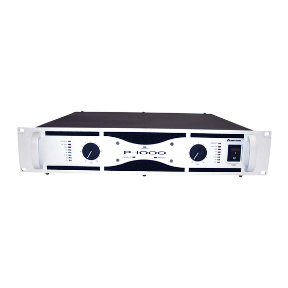
    Panneau avant (1) INTERRUPTEUR ON/OFF (POWER) Pressez cet interrupteur pour mettre l'appareil sous tension. (2) REGULATEUR DE VOLUME Ajustez le volume desiré ici. (3) DEL STEREO Cet DEL est allumé en mode stéreo. (4) DEL PARALLEL Cet DEL est allumé en mode parallel. (5) DEL BRIDGED Cet DEL est allumé...
  • Page 38: Installation

    (14) CH-2 COMBINAISON BANANE/VIS Pour connecter les enceintes de canal 2. (15) CH-1 COMBINAISON BANANE/VIS Pour connecter les enceintes de canal 1. (16) CH-1 DOUILLE DE SORTIE SPEAKER Pour connecter les enceintes de canal 1. (17) REGULATEUR VR FOR LIGHT Pour ajuster l'intensité...
  • Page 39: Raccords De Sortie

    Occupation du jack 6,35 mm symétrique stéréo: RACCORDS DE SORTIE Le fort affaiblissement linéique de votre amplificateur assure une reproduction claire et nette. Des câbles inutilement longs et fins des haut-parleurs peuvent influencer négativement l’affaiblissement linéique et donc les basses fréquences. L’affaiblissement linéique devrait se situer au moins à 50 pour garantir une bonne qualité...
  • Page 40: Mode De Fonctionnement Parallel

    Ne pas oublier: L’impédance des amplificateurs raccordés doit être toujours supérieure ou égale à l’impédance de sortie de l’amplificateur. Procédure: Installer le nombre désiré d’haut-parleurs dans la salle. Raccorder chaque haut-parleur aux autres par les douilles d’entrée et de sortie. Raccorder le câble de raccordement du premier haut-parleur respectivement aux douilles Speaker Output CH-1 et Output CH-2 de l’amplificateur.
  • Page 41: Problèmes

    PROBLEMES PROBLEME: CAUSE: SOLUTION: L'alimentation ne s'enclenche pas. • Le câble d'alimentation n'est pas • Contrôler le câble d'alimentation branché. et les rallonges. Aucun son. • Le câble de connection de • Contrôler le câble de connection l'appareil respectif n'est pas et si les fiches sont raccordées raccordé...
  • Page 42: Caracteristiques Techniques

    Si des pièces de rechange sont nécéssaires, toujours utiliser des pièces d'origine. Quand le câble secteur de cet appareil est endommagé, il doit être remplacé par un câble secteur spécial disponible chez votre revendeur. Pour tout renseignement complémentaire, votre revendeur se tient à votre entière disposition. CARACTERISTIQUES TECHNIQUES P-125, P-250 &...
  • Page 43: Caractéristiques Techniques P-1000, P-1500 & P-2000

    CARACTERISTIQUES TECHNIQUES P-1000, P-1500 & P-2000 P-1000 P-1500 P-2000 Alimentation: 115/230 V AC, 50/60 Hz ~ 115/230 V AC, 50/60 Hz ~ 115/230 V AC, 50/60 Hz ~ Puissance de 1300 W 2120 W 3500 W rendement (max.): Puissance maximale à 1270 W / 4 Ohm 1950 W / 4 Ohm court terme à...
  • Page 44: Caractéristiques Techniques P-3000

    CARACTERISTIQUES TECHNIQUES P-3000 Alimentation: 115/230 V AC, 50/60 Hz ~ Puissance de rendement (max.): 4500 W Puissance de sortie sinus: Stereo 4 Ohm 2 x 1500 W Stereo 8 Ohm 2 x 750 W 8 Ohm en pont 1 x 3000 W Bande de fréquence: 40 - 40 000 Hz, +/- 3 dB Fact amort:...
  • Page 45 Operation modes 45/49 00008423.DOC VERSION 3.2...
  • Page 46 Operation modes 46/49 00008423.DOC VERSION 3.2...
  • Page 47 Operation modes 47/49 00008423.DOC VERSION 3.2...
  • Page 48 Operation modes 48/49 00008423.DOC VERSION 3.2...
  • Page 49 Operation modes 49/49 00008423.DOC VERSION 3.2...

Ce manuel est également adapté pour:

L série

Table des Matières