Publicité
Liens rapides
Mounting Instructions
Montageanleitung
Instructions de montage
Istruzioni di montaggio
Instrucciones de montaje
LIP 481 V
V =
High vacuum
Hochvakuum
Vide poussé
Alto-vuoto
Vacío de alto grado
LIP 481 U
U =
Ultrahigh vacuum
Ultrahochvakuum
Ultravide
Ultravuoto
Ultravacío
7/2013
Publicité

Manuels Connexes pour HEIDENHAIN LIP 481V


Sommaire des Matières pour HEIDENHAIN LIP 481V
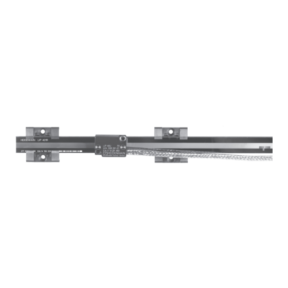
- Page 1 Mounting Instructions Montageanleitung Instructions de montage Istruzioni di montaggio Instrucciones de montaje LIP 481 V High vacuum Hochvakuum Vide poussé Alto-vuoto Vacío de alto grado LIP 481 U Ultrahigh vacuum Ultrahochvakuum Ultravide Ultravuoto Ultravacío 7/2013...
- Page 2 Contents Page Seite Inhalt 3 Warnings 3 Warnhinweise 6 Anwendungshinweise Sommaire 6 Application notes Indice 8 Items supplied 8 Lieferumfang Índice 10 Mounting information 10 Hinweise zur Montage 12 Mounting the scale 12 Anbau des Maßstabs 16 Thermischer Fixpunkt 16 Thermal fixed point 18 Mounting the scanning head 18 Anbau des Abtastkopfes 20 Adjusting the LIP 48 V/U scanning head...
- Page 3 Warnings Warnhinweise Avertissement Avvertenze Advertencias Note: The unit is to be maintained, mounted and commissioned by a qualified specialist under compliance with local safety regulations. Do not engage or disengage any connections while under power. The drive must not be put into operation during installation. Achtung: Die Verwendung/Montage/Inbetriebnahme ist von einer qualifizierten Fachkraft unter Beachtung der örtlichen Sicherheitsvorschriften vorzunehmen.
- Page 4 Warnings Warnhinweise Avertissement Avvertenze Advertencias Do not drop the encoder or subject it to major vibration. Always wear gloves (nitrile) when unpacking and handling the device. Messgerät nicht fallen lassen oder größerer Erschütterung aussetzen. Das Auspacken und die weitere Handhabung darf nur mit Handschuhen (Nitril) erfolgen Ne pas laisser chuter le système de mesure ou lui faire subir des secousses importantes.
- Page 5 Pumping air into or out of the vacuum chamber is only permitted once power has been removed from the encoder. Beim Evakuieren und Belüften der Vakuumkammer muss die elektrische Versorgung des Messgerätes spannungsfrei geschaltet sein. Lors de l'évacuation ou la ventilation de la chambre à vide, l'alimentation électrique du système de mesure doit être mise hors service. Per scarico e pressurizzazione della camera sottovuoto, l'alimentazione elettrica del sistema di misura deve essere disinserita.
- Page 6 Notes on usage –7 High vacuum up to 10 mbar Bake-out temperature 100 °C max. Anwendungshinweise –7 Hochvakuum bis 10 mbar Ausheiz-Temperatur 100 °C max. Instructions d'utilisation –7 Vide poussé jusqu'à 10 mbar Température de dégazage 100 °C max. Avvertenze applicative –7 Alto vuoto fino a 10 mbar...
- Page 7 –11 Ultrahigh vacuum up to 10 mbar Bake-out temperature 120 °C max. –11 Ultrahochvakuum bis 10 mbar Ausheiz-Temperatur 120 °C max. –11 Ultravide jusqu'à 10 mbar Température de dégazage 120 °C max. External shield on housing –11 Ultravuoto fino a 10 mbar Temperatura di bake-out 120 °C max Außenschirm auf Gehäuse...
- Page 8 Items supplied Lieferumfang Fourniture Standard di fornitura Suministro All vacuum encoders are packed in two PET films (transparent plastic packaging) (first film: vacuum, second film: filled with nitrogen). Note! Open the second film only in a clean room. Always wear gloves (nitrile). Alle Vakuumgeräte werden in PET (durchsichtige Kunststoffverpackung) in zwei Folien verpackt (1.
- Page 9 To be ordered separately *) = not magnetic **) = magnetic Separat bestellen nicht magnetisch magnetisch Commander séparément non magnétique magnétique Da ordinare separatamente non magnetico magnetico Pedir por separado no magnético magnético Fixing clamps for fastening the scale and for thermal fixed point. ���������������...
- Page 10 Mounting information Hinweise zur Montage Instructions de montage Avvertenze per il montaggio Indicaciones para el montaje Dimensions in mm Maße in mm Cotes en mm Dimensioni in mm Dimensiones en mm Choose a mounting attitude such that the maximum traverse range is within the measuring length ML of the scale.
- Page 11 Note: Pay attention to the orientation of the scanning head relative to the scale. Do not rotate the scanning head by 180° relative to the scale! Achtung: Ausrichtung Abtastkopf – Maßstab beachten! Abtastkopf relativ zum Maßstab nicht um 180° drehen! Attention: respecter l'alignement tête captrice –...
- Page 12 Mounting the scale Anbau des Maßstabs Montage de la règle de mesure Montaggio della riga Fijación de la escala If mounting with fixing clamps on both edges, use stop pins. Alternative: With shoulder and fixing clamps along only one edge. Bei beidseitiger Befestigung mit Spannpratzen Anschlagstifte verwenden.
- Page 13 �������� �������� � �������� � �������� � � ��� ��� � � � � � � � � � � � � � � � � � � � � � � � � � � � � � � �...
- Page 14 Mounting the scale Anbau des Maßstabs Montage de la règle de mesure Montaggio della riga Fijación de la escala Ensure that the reference-mark *) is positioned correctly. Place the scale onto the stop pins or stop edge and fasten it with the fixing clamps.
- Page 15 Mount further fixing clamps. Remove the stop pins. Weitere Spannpratzen befestigen. Anschlagstifte entfernen. Fixer les autres griffes de serrage. Enlever les goupilles de butée. Fissare le altre staffe di serraggio. Rimuovere le spine di arresto. Fijar mordazas adicionales. Retirar los pasadores de tope.
- Page 16 Thermal fixed point Thermischer Fixpunkt Point fixe thermique Punto fisso termico Punto fijo térmico When using a thermal fixed point fill hollow spaces of the fixture with adhesive. The adhesive hardens at room temperature after approx. 24 hours. See page 17 for use of the adhesive. Bei Verwendung eines Thermischen Fixpunktes Hohlräume des Halters mit Kleber füllen.
- Page 17 �� 1. Open the package and remove the pouch. 2. Pull the ends of the pouch until the clamp falls off. ����� ����� 3. Knead to mix the adhesive a) and hardener b). ���������� ���������� 4. Remove one corner and apply the adhesive. 5.
- Page 18 Mounting the scanning head Anbau des Abtastkopfes Montage de la tête captrice Montaggio della testina Fijación del cabezal captador The mounting surface must be clean and free of paint. ���� Die Anbaufläche muss sauber und lackfrei sein ������ � ������� La surface d'appui doit être propre et sans peinture.
- Page 19 Set the mounting clearance to 0.6 mm with the spacer foil. Do not insert the spacer foil in the area of the fixing clamps. Screw the scanning head on loosely. Comply with the permissible bending radii R of the cable. Mit Abstandsfolie 0,6 mm Montageabstand einstellen.
- Page 20 Adjusting the LIP 48 V/U scanning head Justage des AK LIP 48 V/U Réglage de la tête AK LIP 48 V/U Taratura della testina LIP 48 V/U Ajuste del AK LIP 48 V/U Measuring equipment required for adjustment (see also PWM Operating Instructions): a) Oscilloscope b) PWM 9 c) Module for 1 V...
- Page 21 Connection of LIP 48 V/U scanning head via PWM 9 to oscilloscope. Note: Do not engage connectors while unit is under power! Anschluss des AK LIP 48 V/U über das PWM 9 an das Oszilloskop. Achtung: Steckverbindungen nicht unter Spannung durchführen! Connexion de la tête AK LIP 48 V/U à...
- Page 22 Adjusting the LIP 48 V/U scanning head Justage des AK LIP 48 V/U Réglage de la tête AK LIP 48 V/U Taratura della testina LIP 48 V/U Ajuste del AK LIP 48 V/U Move the scanning head back and forth to check the output signals. Zur Prüfung der Ausgangssignale Maßstab hin- und herfahren.
- Page 23 Amplitudes of the incremental signals Amplitude ratio PHA: Phase angle TV1, TV2: On-off ratios SYM.A, SYM.B: Asymmetry If the specified tolerances are not met, check the mounting tolerances again. Amplituden der Inkrementalsignale Amplitudenverhältnis PHA: Phasenwinkel TV1, TV2: Tastverhältnisse SYM.A, SYM.B: Symmetrieabweichungen Können die angegebenen Toleranzen nicht eingehalten werden, nochmals Montagetoleranzen überprüfen.
- Page 24 Adjusting the Reference Marks Referenzmarken justieren Réglage marques de référence Taratura indice di riferimento Ajuste de las marcas de referencia Assign the BNC sockets on the PWM 9 as follows: BNC A: R (reference mark signal) BNC B: A+B (Sum signal A Am PWM 9 die BNC Buchsen wie folgt belegen: BNC A: R (Referenzmarkensignal) BNC B: A+B (Summensignal A...
- Page 25 Lightly tap to adjust the reference mark signal. The peak of the reference mark signal should be level with the peak of the sum signal. To fasten the scanning head, tighten the screws. Note: Ensure that the incremental signals do not become smaller. Durch leichtes Klopfen Referenzmarkenlage justieren.
- Page 26 895626-90 · Ver00 · Printed in Germany · 7/2013 · H...