Table des Matières
Publicité
Liens rapides
For mounting the linear scale and scale tapes, please refer to the separate Mounting Instructions.
Für Montage des Maßstabes und Maßbänder bitte separate Anleitung beachten.
Pour le montage de la règle et des rubans de mesure, veuillez tenir compte des instructions distinctes.
Per il montaggio della riga graduata e dei nastri graduati attenersi alle istruzioni separate.
Para el montaje de la regla y las cintas de medida deben consultarse las instrucciones de montaje
suministradas por separado.
Mounting Instructions
Montageanleitung
Instructions de montage
Istruzioni di montaggio
Instrucciones de montaje
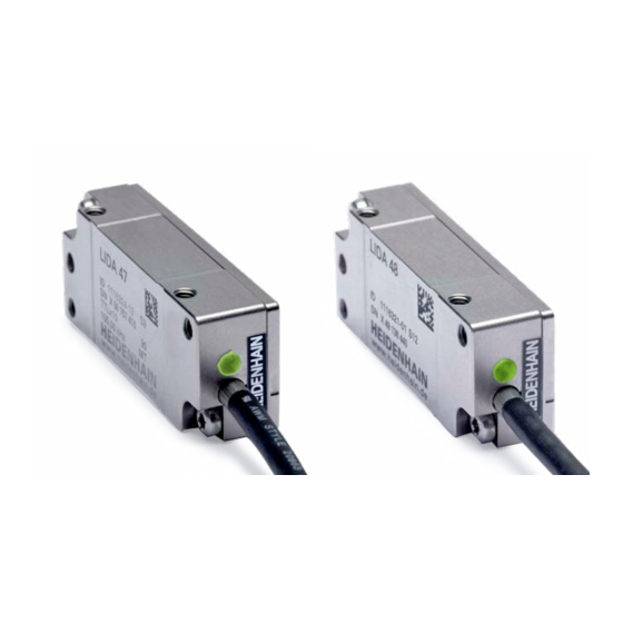
AK LIDA 47
AK LIDA 48
Scanning head
Abtastkopf
Tête captrice
Testina di scansione
Cabezal captador
03/2020
Publicité
Table des Matières

Manuels Connexes pour HEIDENHAIN AK LIDA 47


Sommaire des Matières pour HEIDENHAIN AK LIDA 47
- Page 1 Montageanleitung Instructions de montage Istruzioni di montaggio Instrucciones de montaje AK LIDA 47 AK LIDA 48 Scanning head For mounting the linear scale and scale tapes, please refer to the separate Mounting Instructions. Für Montage des Maßstabes und Maßbänder bitte separate Anleitung beachten.
- Page 2 Contents Page Seite Inhalt Warnings Warnhinweise Sommaire Mounting Options for the Scanning Head Montagemöglichkeiten des Abtastkopfes Indice Items Supplied Lieferumfang Mounting Montage Indice 10 Adjustment 10 Justage 15 Adjusting the position of the reference mark 15 Justage der Referenzmarkenlage 17 Checking the Status Display 17 Funktionsanzeige überprüfen 18 Mounting the Magnets for Limit Switches 18 Anbau der Magneten für Limitschalter...
-
Page 3: Avertissements
Warnings Warnhinweise Avertissements Avvertenze Advertencias Note: Mounting and commissioning is to be conducted by a qualified specialist under compliance with local safety regulations. Do not engage or disengage any connections while under power. The system must be disconnected from power. Achtung: Die Montage und Inbetriebnahme ist von einer qualifizierten Fachkraft unter Beachtung der örtlichen Sicherheitsvorschriften vorzunehmen. - Page 4 Mounting Options for the Scanning Head The scanning head must be rotatable for adjustment. Montagemöglichkeiten des Abtastkopfes Für die Justage muss der Abtastkopf drehbar sein. Possibilités de montage de la tête captrice Pour le réglage, il faut que la tête captrice soit pivotable. Varianti di montaggio della testina Per la taratura la testina deve essere libera di ruotare.
- Page 5 When you use mounting option , you can use the blind hole in the scanning head for adjusting the scanning head. Für die Justage des Abtastkopfes bei der Anbaumöglichkeit kann das Sackloch im Abtastkopf verwendet werden. Lors du réglage de la tête captrice selon l‘option de montage , il est possible d‘utiliser le trou borgne situé dans la tête captrice. Per la taratura della testina nella versione di montaggio ...
-
Page 6: Items Supplied
Items Supplied Lieferumfang Contenu de la livraison Standard di formitura Suministro LIDA 47/LIDA 48 scanning head, spacer foil Abtastkopf LIDA 47/LIDA 48, Abstandsfolie Tête captrice LIDA 47/LIDA 48, feuille d’écartement Testina LIDA 47/LIDA 48, pellicola distanziale Cabezal de captación LIDA47/LIDA 48, lámina espaciadora... -
Page 7: Montage
Mounting Montage Montage Montaggio Montaje Remove the protective cover! If necessary, clean the graduation and the scanning head with a lint-free cloth and isopropyl alcohol. Schutzkappe entfernen! Bei Bedarf Teilung und Abtastkopf mit fusselfreiem Tuch und Isopropylalkohol reinigen. Retirer le bouchon de protection! En cas de besoin, nettoyer la division et la tête captrice avec un chiffon sans peluches et de l’alcool isopropylique. - Page 8 Use the spacer foil to set the mounting clearance. Fasten the scanning head so that it can still be adjusted. Mit Abstandsfolie Montageabstand einstellen. Abtastkopf soweit festschrauben, dass er noch zu justieren ist. Utiliser la feuille d’écartement pour définir la distance de montage. Visser la tête captrice de telle sorte qu’elle puisse encore être ajustée.
- Page 9 Check the resistance between the connector housing and the machine. Desired value: < 1 Elektrischen Widerstand zwischen Steckergehäuse und Maschine prüfen. Sollwert: < 1 Vérifier la résistance électrique entre le boîtier du connecteur et la machine. Valeur nominale: < 1 Controllare la resistenza elettrica tra l’alloggiamento del connettore e la macchina.
-
Page 10: Adjustment
Adjustment Justage Réglage Taratura Ajuste Perform the adjustment using the PWT 100/PWT 101 encoder diagnostic set. Please refer to the PWT 100/PWT101 operating/installation instructions (included on CD), chapter “Diagnostics of the measuring devices. ” As an alternative, a PWM 20/PWM 21/PWM 9 encoder diagnostic set can be used. Justage mit Messgerät-Diagnoseset PWT 100/PWT 101 durchführen. - Page 11 Do not connect while powered! Steckverbindung nicht unter Spannung durchführen! Ne procéder à aucun branchement sous tension ! Non eseguire i collegamenti sotto tensione! ¡No efectuar las conexiones de enchufe bajo tensión! PWT 10x In the main menu of the PWT 10x, select “Automatic Diagnosis” Im Hauptmenü...
- Page 12 LIDA 48 (1 V The PWT display view makes it possible to use moving-bar graphics for the evaluation of incremental signals and reference mark signals. Die Ansicht PWT-Anzeige ermöglicht mit Balkendiagrammen eine Bewertung von Inkremental- und Referenzmarkensignalen. La vue «Affichage du PWT» permet d’évaluer les signaux incrémentaux et les signaux de référence à...
- Page 13 LIDA 47 (TTL) Swipe the „Level display“ screen to the right Bildschirm “Pegelanzeige” nach rechts wischen Effleurer l’écran «Affichage niveau» vers la droite Scorrere verso destra nella videata “Visualizzazione livello” Limpiar hacia la derecha la pantalla «Visualización Pegel» „HSP OFF“ when flashing: OK „HSP OFF“...
- Page 14 LIDA 47 (TTL) The black bar represents the current signal amplitude of the incremental signals. The farther the black bar moves to the right, the greater the signal amplitude is. Der schwarze Balken zeigt die aktuelle Signalamplitude der Inkrementalsignale an. Je weiter der schwarze Balken nach rechts wandert, umso größer ist die Signalamplitude La barre noire indique l’amplitude actuelle des signaux incrémentaux.
- Page 15 LIDA 48 (1 V ) & LIDA 47 (TTL) Adjusting the position of the reference mark Justage der Referenzmarkenlage Réglage de la position de la marque de référence Taratura della posizione dell’indice di riferimento Ajuste de la posición de la marca de referencia Traverse the reference mark with the scanning head.
- Page 16 Green = good Optimum Grün = gut, Optimal Vert = bien Optimal RM.Pos. Verde = ok Ottimale Verde = correcto Óptimo Tap lightly to rotate the scanning head a minimum distance. Ensure that the incremental signals do not decrease. Durch leichtes Klopfen den Abtastkopf minimal verdrehen. Darauf achten, dass Inkrementalsignale nicht kleiner werden.
- Page 17 Checking the Status Display Status Display Funktionsanzeige überprüfen Funktionsanzeige Contrôle du témoin fonctionnel Témoin fonctionnel Verifica della funzionalità Indicatore di funzionalità Comprobar el indicador de función Indicador de función If the LED blinks green after adjustment, check the mounting tolerance and repeat the adjustment. Wenn nach der Justage die LED grün blinkt, Anbautoleranz überprüfen und Justage neu durchführen.
-
Page 18: Mounting The Magnets For Limit Switches
Mounting the Magnets for Limit Switches Magnete anbauen für Limitschalter Montage des aimants pour commutateurs de fin de course Montaggio dei magneti per finecorsa Montaje de los imanes para el contacto final de carrera The limit switches can be used to indicate the end of the machine traversing range. - Page 19 Swipe to the “Switching signals“ screen Zum Bildschirm “Schaltsignale” wischen Passer à l’écran “Signaux de commutation“ par un effleurement du doigt A video, far scorrere il dito su “Segnali di commutazione” Borrar en la pantalla «Señales de palpación» Move the scanning head to the desired position and move the magnet until diode L1 or L2 lights up. Mark the position of the magnet (ensure that the mounting surface is clean), peel off the protective foil and apply the magnet.
- Page 20 DR. JOHANNES HEIDENHAIN GmbH Dr.-Johannes-Heidenhain-Straße 5 83301 Traunreut, Germany { +49 8669 31-0 | +49 8669 32-5061 E-mail: info@heidenhain.de Technical support | +49 8669 32-1000 Measuring systems { +49 8669 31-3104 E-mail: service.ms-support@heidenhain.de TNC support { +49 8669 31-3101 E-mail: service.nc-support@heidenhain.de...