Extel WECA 109057 Mode D'emploi Et D'installation

Extel WECA 109057 Mode D'emploi Et D'installation

Verrou autonome avec pene en applique
Masquer les pouces Voir aussi pour WECA 109057:

Publicité

Les langues disponibles
  • FR

Les langues disponibles

  • FRANÇAIS, page 1

Liens rapides

WECA 109057
08-08 V1
VERROU AUTONOME AVEC PENE EN APPLIQUE
Pour porte de 35 mm à 60 mm
Pour une ouverture à gauche ou à droite - Gabarit de pose
ZELFSTANDIG SLOT MET SCHOOT ALS OPLEGPLAAT
Voor deur van 35 tot 60 mm
Links openend of rechts openend - Installatiemodel (mal)
AUTONOMES TÜRSCHLOSS MIT FALLE UND SCHLIESSBLECH
ZUM AUF- ODER EINSETZEN
Türstärken von 35 mm bis 60 mm
Links oder rechts öffnend - Montageschablone
SURFACE-MOUNTED AUTONOMOUS BOLT
For door from 35 mm to 60 mm
For left or right hand opening - Installation template
SERRATURA A CODICE CON SCROCCO DA APPLICARE
Per porta da 35 mm a 60 mm
Per apertura mano destra o sinistra - Sagoma di montaggio
SISTEMA DE BLOQUEO AUTÓNOMO CON PESTILLO DE SOBREPONER
Para puertas de 35-60 mm
Para una apertura hacia la izquierda o hacia la derecha - Plantilla de montaje
FECHADURA AUTÓNOMA COM LINGUETA EM APLIQUE
Para porta de 35 mm a 60 mm
Para uma abertura à esquerda ou à direita - Modelo de instalação
M
'
'
ODE D
EMPLOI ET D
INSTALLATION
H
ANDLEIDING VOOR INSTALLATIE EN GEBRUIK
I
-
B
NSTALLATIONS
UND
EDIENUNGSANLEITUNG
I
NSTALLATION AND OPERATION MANUAL
I
STRUZIONI DI UTILIZZO E INSTALLAZIONE
I
NSTRUCCIONES DE USO E INSTALACIÓN
MODO DE EMPREGO E DE INSTALAÇÃO

Publicité

Table des Matières
loading

Sommaire des Matières pour Extel WECA 109057

  • Page 1 WECA 109057 08-08 V1 VERROU AUTONOME AVEC PENE EN APPLIQUE Pour porte de 35 mm à 60 mm Pour une ouverture à gauche ou à droite - Gabarit de pose ZELFSTANDIG SLOT MET SCHOOT ALS OPLEGPLAAT Voor deur van 35 tot 60 mm Links openend of rechts openend - Installatiemodel (mal) AUTONOMES TÜRSCHLOSS MIT FALLE UND SCHLIESSBLECH...
  • Page 2 60mm 60mm...
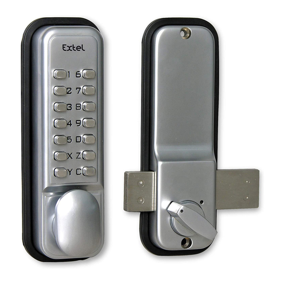
  • Page 3: Liste Des Pieces

    1. LISTE DES PIECES a) Bloc clavier. b) Bloc intérieur. c) 2 flasques néoprènes. d) Carré. e) Gâche à encastrer. f) Gâche en applique. g) Vis de fixation. h) Vis d’assemblage. 2. AVANT DE COMMENCER LA POSE a - Vérifier que toutes les pièces fonctionnent correctement ensemble. b - Choisir un code en suivant les instructions «modifications du code d’entrée».
  • Page 4: Modifications Du Code D'entrée

    Modifications du code d’entrée : Vous avez la possibilité d’utiliser une partie ou tous les fig. M poussoirs pour coder l’ouverture par la poignée. Aucun ordre dans la numérotation n’est demandé. Sur le dos du clavier “fig. M” on peut apercevoir les éléments qui prolongent les poussoirs du clavier.
  • Page 5: Configuration Du Verrou Pour Une Ouvertureà Gauche Ou À Droite

    4. CONFIGURATION DU VERROU POUR UNE OUVERTURE À GAUCHE OU À DROITE Si besoin vous avez la possibilité d’inverser le sens du déverrouillage. a - Pressez le bouton « C » pour remettre à zéro le mécanisme. b - Enlevez la plaque centrale du boîtier en retirant préalablement les 2 vis (repère Z). c - A l’aide d’une petite pince, retirez la goupille et la repositionner à...
  • Page 6: Positionnement Du Verrou

    5. POSITIONNEMENT DU VERROU IMPORTANT : Déterminez la gâche qu’il convient d’utiliser (encastrée ou en applique) et tracez sa position sur le cadre avant de percer la porte. ATTENTION : Le pêne sort de 35 mm par rapport au côté du verrou. Présentez le bloc intérieur avec la poignée en position verticale et tenez-le sur la porte avec une extrémité...
  • Page 7: Installation De La Gache

    7. INSTALLATION DE LA GACHE 8. 1 Gâche encastrée Gâche en applique En premier, choisir le type de gâche qui convient pour votre porte puis positionnez la gâche sur le cadre de telle sorte qu’elle soit alignée avec le pêne et marquer les trous correspondants. Si vous utilisez la gâche en applique, vissez la simplement (figure 8.1).
  • Page 8 1. LIJST VAN DE ONDERDELEN a) Toetsenpaneel b) Toetsenpaneel binnen. c) 2 zijpanelen van neopreen. d) Stift. e) In te bouwen schootplaat. f) Schootplaat als oplegplaat. g) Bevestigingsschroeven. h) Assemblageschroeven. 2. VOORDAT U DE INSTALLATIE BEGINT a - Controleer of alle onderdelen samen juist functioneren. b - Kies een code door de instructies “wijzigingen van de toegangscode”...
  • Page 9 Wijzigingen van de toegangscode: U hebt de mogelijkheid om een gedeelte, of alle fig. M knoppen te gebruiken om de toegang via de deurknop te coderen. Er wordt geen enkele volgorde in de nummering gevraagd. Aan de achterkant van het paneel “afb. M” kunnen we de elementen zien die de knoppen van het toetsenpaneel verlengen.
  • Page 10 4. CONFIGURATIE VAN HET SLOT VOOR EEN OPENING NAAR LINKS OF NAAR RECHTS Wanneer nodig, kunt u de richting van de ontgrendeling omdraaien. a – Druk op knop “C” om het mechanisme weer op nul te zetten. b – Haal de centrale plaat van het kastje weg, door vooraf de 2 schroeven weg te nemen (afb. Z). c –...
  • Page 11 5. POSITIONERING VAN HET SLOT BELANGRIJK: Bepaal de schootplaat die geschikt is voor gebruik (ingebouwd of als oplegplaat) en geef zijn positie aan op het kozijn voordat u Montage rechterhand in de deur gaat boren. ATTENTIE: De schoot steekt 35 mm uit met betrekking tot de zijkant van het slot.
  • Page 12 7. INSTALLATIE VAN DE SCHOOTPLAAT 8.2 - Ingebouwde schootplaat 8. 1 - Schootplaat als oplegplaat Als eerste kiest u het type schootplaat dat het beste bij uw deur past en zet u de schootplaat zo op het kozijn, dat deze in lijn ligt met de schoot. U markeert de overeenkomende gaten. Wanneer u de schootplaat als oplegplaat gebruikt, schroeft u deze eenvoudigweg vast (tekening 8.1).
  • Page 13: Vor Dem Einbau

    1. STÜCKLISTE a) Tastaturblock b) Innenblock c) 2 Neopren-Blenden d) Vierkant e) Schließblech zum Einsetzen f) Schließblech zum Aufsetzen g) Befestigungsschrauben h) Verbindungsschrauben 2. VOR DEM EINBAU a – Prüfen Sie, ob alle Teile korrekt zusammen funktionieren. b – Wählen Sie einen Code aus. Folgen Sie den Anweisungen „Änderungen des Eingangscodes“. c –...
  • Page 14 Änderungen des Eingangscodes: Sie haben die Möglichkeit, einen Teil der Tasten bzw. fig. M alle Tasten zu nutzen, um die Öffnung per Griff zu codieren. Die Zahlen können in beliebiger Reihenfolge eingegeben werden. Auf der Rückseite der Tastatur “fig. M” sieht man die Verlängerungselemente der entsprechenden Tasten der Tastatur.
  • Page 15 4. EINSTELLEN DES TÜRSCHLOSSES FÜR EINE ÖFFNUNG NACH LINKS ODER NACH RECHTS Falls erforderlich, können Sie die Richtung der Entriegelung ändern. a – Drücken Sie auf die Taste “C”, um den Mechanismus auf Null zurückzustellen. b – Entfernen Sie den Deckel in der Mitte des Gehäuses, nachdem Sie die 2 Schrauben entfernt haben (siehe Z).
  • Page 16 5. DAS TÜRSCHLOSS POSITIONIEREN WICHTIG: Wählen Sie das geeignete Schließblech (zum Ein- oder Aufsetzen) und zeichnen Sie seine Position am Rahmen an, bevor Sie die Löcher bohren. ACHTUNG: Die Falle muss im Verhältnis zur Seite des Schlosses 35 mm hervor stehen. Halten Sie den Innenblock mit dem Griff in der vertikalen Lage.
  • Page 17 7. EINBAU DES SCHLIESSBLECHS Schließblech zum Schließblech zum Einsetzen Aufsetzen Wählen Sie zunächst das für Ihre Tür geeignete Schließblech aus. Wählen Sie dann eine Position für Ihr Schließblech auf dem Rahmen, so dass es mit der Falle auf einer Linie liegt, und markieren Sie die entsprechenden Löcher für die Bohrung.
  • Page 18: List Of Parts

    1. LIST OF PARTS a) Keyboard. b) Internal block. c) 2 neoprene flanges. d) Square. e) Flush-mounted strike. f) Surface-mounted strike. g) Attachment screws. h) Assembly screws. 2. BEFORE STARTING THE INSTALLATION a – Check all pieces work properly together. b –...
  • Page 19 Modifications of the entry code : You can use part of or all the push-buttons to code the fig. M opening through the handle. No order in the numbering is requested. At the back of the keyboard “fig. M” we can see the elements extending the push-buttons of the keyboard.
  • Page 20 4. CONFIGURATION OF THE LOCK FOR LEFT HAND OR RIGHT HAND OPENING If needed, you can reverse the unlocking direction. a. Press the button “C” to reset the mechanism. b. Remove the central plate of the box by previously unscrewing the 2 screws (mark Z). c.
  • Page 21 5. POSITIONING THE LOCK IMPORTANT: Determine strike (flush-mounted or surface-mounted) and mark its position on the frame before drilling the door. CAUTION: The bolt is 35 mm taller regarding the side of the lock. Present the internal block with the handle in vertical position and hold it on the door with an end of the bolt aligned with the frame where the strike will be installed (see step 7).
  • Page 22: Installing The Strike

    7. INSTALLING THE STRIKE 8. 1 Flush-mounted strike Surface-mounted strike First, choose the relevant type of strike for your door and then place the strike on the frame so that it is aligned with the bolt and mark the corresponding holes. If you use the surface-mounted strike, only screw it (figure 8.1).
  • Page 23: Lista Dei Pezzi

    1. LISTA DEI PEZZI a) Blocco tastiera b) Blocco interno c) 2 flange neoprene d) Quadro e) Incontro a incasso f) Incontro da applicare g) Viti di fissaggio h) Viti di assemblaggio 2. PRIMA DI COMINCIARE LA POSA a – Verificare che tutti i pezzi funzionino correttamente insieme. b –...
  • Page 24 Modifica del codice di entrata: È possibile utilizzare tutti o solo una parte dei fig. M pulsanti per codificare l’apertura per mezzo della maniglia. Non è richiesto alcun ordine nella numerazione. Sul retro della tastiera “fig. M” si possono scorgere gli elementi che prolungano i pulsanti della tastiera.
  • Page 25 4. CONFIGURAZIONE DELLA SERRATURA PER APERTURA A DESTRA O A SINISTRA All’occorrenza è possibile invertire il senso di apertura. a – Premere il pulsante « C » per rimettere a zero il meccanismo. b – Togliere la mascherina centrale avendo in precedenza tolto le 2 viti (riferimento Z). c –...
  • Page 26 5. POSIZIONAMENTO DELLA SERRATURA IMPORTANTE: Definire l’incontro idoneo all’utilizzo (a incasso o da applicare) e tracciarne la posizione sul telaio prima di forare la porta. ATTENZIONE: Lo scrocco sporge di 35 mm rispetto al lato della serratura. Mantenere il blocco interno con la maniglia in posizione verticale e tenerlo sulla porta con un’estremità...
  • Page 27 7. INSTALLAZIONE DELL’INCONTRO 8. 1 Incontro a incasso. Incontro da applicare. Innanzitutto scegliere il tipo di incontro idoneo alla porta, poi posizionare l’incontro sul quadro in maniera tale che sia allineato con lo scrocco e segnare i fori corrispondenti. Se si utilizza l’incontro da applicare, avvitarlo semplicemente (figura 8.1). Utilizzare i pezzi forniti se necessario.
  • Page 28: Lista De Piezas

    1. LISTA DE PIEZAS a) Bloque teclado. b) Bloque interior. c) 2 placas de neopreno. d) Pasador cuadrado. e) Cerradero para encastrar. f) Cerradero de sobreponer. g) Tornillo de fijación. h) Tornillo de unión. 2. ANTES DE PROCEDER AL MONTAJE a –...
  • Page 29 Modificación del código de entrada: fig. M Puede utilizar todos o parte de los pulsadores para codificar la apertura por medio de la palanca. No es necesario respetar ningún orden. En la parte trasera del teclado (ver fig. M) se pueden ver elementos que prolongan los pulsadores del teclado.
  • Page 30 4. CONFIGURACIÓN DEL SISTEMA DE BLOQUEO PARA UNA APERTURA HACIA LA IZQUIERDA O HACIA LA DERECHA En caso de necesidad, puede invertir el sentido del desbloqueo. a – Pulse el botón “C” para reiniciar el mecanismo b – Retire la placa central de la caja sacando previamente los 2 tornillos (referencia Z). c –...
  • Page 31 5. INSTALACIÓN DEL SISTEMA DE BLOQUEO IMPORTANTE: Determine el cerradero que conviene utilizar (encastrado o de sobreponer) y trace su posición en el marco antes de perforar la puerta. ATENCIÓN: El pestillo sobresale 35 mm con respecto al lado del sistema de bloqueo. Presente el bloque interior con la palanca en posición vertical y sujételo contra la puerta con un extremo del pestillo alineado con el marco donde se instalará...
  • Page 32 7. INSTALACIÓN DEL CERRADERO 8. 1 Cerradero encastrado Cerradero de sobreponer En primer lugar, escoja el tipo de cerradero más adaptado a su puerta y luego, coloque el cerradero contra el marco de manera que quede alineado con el pestillo, y marque los agujeros correspondientes.
  • Page 33: Lista Das Peças

    1. LISTA DAS PEÇAS a) Bloco teclado. b) Bloco interior. c) 2 placas de neoprene. d) Quadro. e) Chapa-testa a encaixar. f) Chapa-testa em aplique. g) Parafusos de fixação. h) Parafusos de montagem. 2. ANTES DE COMEÇAR A INSTALAÇÃO a - Verificar se todas as peças funcionam juntas correctamente. b - Escolher um código seguindo as instruções “modificações do código de entrada”.
  • Page 34: Verifique O Sentido De Abertura Da Sua Porta

    Modificações do código de entrada: Tem a possibilidade de utilizar uma parte ou todos os fig. M botões para codificar a abertura através da pega. Nenhuma ordem na numeração é pedida. Nas costas do teclado “fig. M” pode-se ver os elementos que prolongam os botões do teclado.
  • Page 35 4. CONFIGURAÇÃO DA FECHADURA PARA UMA ABERTURA À ESQUERDA OU À DIREITA Se for necessário tem a possibilidade de inverter o sentido do desbloqueio. a - Pressione o botão “C” para colocar em zero o mecanismo. b - Retire a placa central da caixa retirando previamente os 2 parafusos (sinal Z). c - Com a ajuda de uma pinça pequena, retire a lingueta e reposicione no lado oposto (a lingueta deve entrar na parte inferior, para conseguir com êxito esta operação posicione os 2 orifícios horizontalmente.
  • Page 36 5. POSICIONAMENTO DA FECHADURA IMPORTANTE: Determine a chapa-testa que convém utilizar (encaixada ou em aplique) e trace a sua posiçãono quadro dianteiro antes de furar a porta. ATENÇÃO: A lingueta sai de 35 mm em relação ao lado da fechadura. Apresente o bloco interior com a pega em posição vertical e aguente-a sobre a porta com uma extremidade da lingueta alinhada com o quadro onde a chapa-testa será...
  • Page 37 7. INSTALAÇÃO DA CHAPA-TESTA 8. 1 Chapa-testa encaixada Chapa-testa em aplique Primeiramente, escolher o tipo de chapa-testa que convém para a sua porta em seguida posicione a chapa-testa sobre o quadro de modo que fique alinhada com a lingueta e marque os orifícios correspondentes.

Table des Matières