Table des Matières
Publicité
Liens rapides
Betriebs- und Installationsanleitung Anzeigegerät
Operating and Installation Instructions Display device
Instructions d'utilisation et d'installation Appareil d'affichage
D, CZ, E, F, GB, I, NL, P, PL, RUS, DK, EST, H, N, RO, S, SF, SK, SLO, TR
KERN IFB
Version 2.0
03/2012
KERN & Sohn GmbH
Ziegelei 1
D-72336 Balingen
E-Mail: info@kern-sohn.com
Tel: +49-[0]7433- 9933-0
Fax: +49-[0]7433-9933-149
Internet: www.kern-sohn.com
Artikel-Nr.
KK
gae
112 408
130 708
112 409
130 709
112 411
130 710
112 412
130 711
112 413
130 712
112 414
130 713
112 415
130 714
112 416
130 715
Publicité
Chapitres
Table des Matières

Sommaire des Matières pour KERN&SOHN KFB-TM
- Page 1 KERN & Sohn GmbH Ziegelei 1 Tel: +49-[0]7433- 9933-0 D-72336 Balingen Fax: +49-[0]7433-9933-149 E-Mail: info@kern-sohn.com Internet: www.kern-sohn.com Betriebs- und Installationsanleitung Anzeigegerät Operating and Installation Instructions Display device Instructions d’utilisation et d’installation Appareil d’affichage D, CZ, E, F, GB, I, NL, P, PL, RUS, DK, EST, H, N, RO, S, SF, SK, SLO, TR KERN IFB Version 2.0 03/2012...
-
Page 2: Table Des Matières
KERN KFB/KFN-TM Version 2.0 02/2012 Betriebs- und Installationsanleitung Anzeigegeräte Inhaltsverzeichnis Technische Daten ..................4 Geräteübersicht ..................... 5 Tastaturübersicht ........................7 2.1.1 Numerische Eingabe über Navigationstasten ................8 Anzeigenübersicht ........................8 Grundlegende Hinweise (Allgemeines) ............9 Bestimmungsgemäße Verwendung ................... 9 Sachwidrige Verwendung ......................9 Gewährleistung ........................... - Page 3 Betrieb ......................24 Einschalten ..........................24 Ausschalten ..........................24 Nullstellen ..........................24 Einfaches Wägen ........................24 Wägeeinheit umschalten (nur nicht eichfähige Wägesysteme) ..........25 Wägen mit Tara ........................26 Wägen mit Toleranzbereich ..................... 26 Manuelles Summieren ......................29 Automatisches Summieren ...................... 31 7.10 Stückzählen ..........................
-
Page 4: Technische Daten
1 Technische Daten KERN KFB-TM KFN-TM Anzeige 5 ½ - stellig Auflösung (geeicht) 6000 Single (Max.) 6.000 e Dual (Max.) 3.000 e Auflösung (nicht geeicht) 30.000 Wägebereiche Ziffernschritte 1,2,5,…10n Wägeeinheiten Funktionen Wägen mit Toleranzbereich, Summieren, Tierwägen Display LCD 52 mm Ziffern, hinterleuchtet 80-100 Ω. -
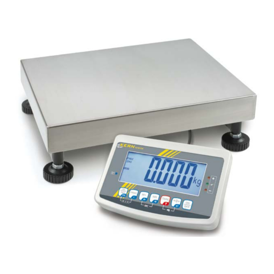
Page 5: Geräteübersicht
2 Geräteübersicht KFB-TM: Kunststoffausführung 1. Akkuzustand 2. Tastenfeld 3. Gewichtsanzeige 4. Toleranzmarke, s. Kap. 7.7 5. Wägeeinheit 6. RS-232 7. Eingang Anschluss Lastzellenkabel 8. Führungsschiene Tischfuß/Stativ 9. Anschlag Tischfuß/Stativ 10. Anschluss Netzadapter 11. Justierschalter KFB/KFN-TM-BA_IA-d-1220... - Page 6 KFN-TM: Edelstahlausführung 1. Akkuzustand 2. Tastenfeld 3. Gewichtsanzeige 4. Toleranzmake. S. Kap. 7.7 5. Wägeeinheit 6. Eingang Anschluss Lastzellenkabel 7. Anschluss Netzadapter KFB/KFN-TM-BA_IA-d-1220...
-
Page 7: Tastaturübersicht
2.1 Tastaturübersicht Taste Funktion • Ein-/Ausschalten • Nullstellen • Eingabe bestätigen Navigationstaste • Tarieren • Bei numerischer Eingabe blinkende Ziffer erhöhen Navigationstaste • Im Menü vorwärts blättern • Anzeige Gesamtsumme • Ziffernanwahl nach rechts Navigationstaste • Wägewert in Summenspeicher addieren •... -
Page 8: Numerische Eingabe Über Navigationstasten
2.1.1 Numerische Eingabe über Navigationstasten drücken, die aktuelle Einstellung wird angezeigt. Die erste Ziffer blinkt und kann jetzt geändert werden. Soll die erste Ziffer nicht geändert werden drücken, die zweite Ziffer be- ginnt zu blinken. Bei jedem Drücken von wechselt die Anzeige zur nachfolgenden Ziffer, nach der letzten Ziffer wechselt die Anzeige wieder zur ersten Ziffer. -
Page 9: Grundlegende Hinweise (Allgemeines)
3 Grundlegende Hinweise (Allgemeines) 3.1 Bestimmungsgemäße Verwendung Das von Ihnen erworbene Anzeigegerät in Kombination mit einer Wägeplatte dient zum Bestimmen des Wägewertes von Wägegut. Es ist zur Verwendung als „nicht- selbsttätiges Wägesystem“ vorgesehen, d.h. das Wägegut wird manuell, vorsichtig und mittig auf die Wägeplatte aufgebracht. Nach Erreichen eines stabilen Wägewertes kann der Wägewert abgelesen werden. -
Page 10: Prüfmittelüberwachung
3.4 Prüfmittelüberwachung Im Rahmen der Qualitätssicherung müssen die messtechnischen Eigenschaften des Anzeigegerätes und eines eventuell vorhandenen Prüfgewichtes in regelmäßigen Abständen überprüft werden. Der verantwortliche Benutzer hat hierfür ein geeignetes Intervall sowie die Art und den Umfang dieser Prüfung zu definieren. Informationen bezüglich der Prüfmittelüberwachung von Anzeigegeräten sowie der hierfür notwen- digen Prüfgewichte sind auf der KERN- Homepage (www.kern-sohn.com) verfügbar. -
Page 11: Auspacken Und Aufstellen
6 Auspacken und Aufstellen 6.1 Aufstellort, Einsatzort Die Anzeigegeräte sind so konstruiert, dass unter den üblichen Einsatzbedingungen zuverlässige Wägeergebnisse erzielt werden. Exakt und schnell arbeiten Sie, wenn Sie den richtigen Standort für Ihr Anzeigegerät und Ihre Wägeplatte wählen. Am Aufstellort folgendes beachten: •... -
Page 12: Transportsicherung (Abbildungsbeispiel)
6.4 Transportsicherung (Abbildungsbeispiel) Bitte Beachten, wenn Anzeigegerät in Verbindung mit einer Plattform mit Transport- sicherung verwendet wird, muss diese Transportsicherung vor Verwendung gelöst werden. Transportsicherung 6.5 Fehlermeldung Sobald in der Anzeige der Waage eine Fehlermeldung erscheint, darf die Waage nicht mehr eingesetzt werden. z. Bsp. Err 4 KFB/KFN-TM-BA_IA-d-1220... -
Page 13: Aufstellen
6.6 Aufstellen Das Anzeigegerät so aufstellen, dass es gut bedient und eingesehen werden kann. Verwendung mit Tischfuß (nur KFB-TM) Aufnahme Tischfuß in Führungsschiene [8] bis Anschlag [9] schieben, s. Kap. 2. Verwendung mit Wandhalterung (nur KFB-TM) Anzeigegerät mit der Wandhalterung an der Wand anbringen. -
Page 14: Netzanschluss
6.7 Netzanschluss Die Stromversorgung erfolgt über das externe Netzgerät. Der aufgedruckte Span- nungswert muss mit der örtlichen Spannung übereinstimmen. Verwenden Sie nur KERN- Originalnetzgeräte. Die Verwendung anderer Fabrikate bedarf der Zustimmung von KERN. 6.8 Akkubetrieb (Option) Der Akku sollte vor der ersten Benutzung mindestens 12 Stunden über das Netzteil geladen werden. -
Page 15: Justierung
• 6.9.1 Geeichte Wägesysteme Bei geeichten Wägesystemen ist der Menüpunkt für die Justierung „P2 mode“ gesperrt. KERN KFB-TM Um die Zugriffsperre aufzuheben, muss die Siegelmarke zerstört und der Jus- tierschalter betätigt werden. Position des Justierschalters siehe Kap. 6.11. KERN KFN-TM Um die Zugriffsperre aufzuheben, muss vor Menüaufruf die Siegelmarke zer-... - Page 16 Menü aufrufen: 1. Gerät einschalten und während des Selbsttests drücken. nacheinander drücken der erste Menüblock „PO CHK“ wird angezeigt.. wiederholt drücken, bis „P2 mode“ angezeigt wird. Bei Modell KFB-TM Justierschalter betätigen. drücken und mit eingestellten Waagentyp auswäh- len. = Einbereichswaage = Zweibereichswaage ...
- Page 17 Justierung durchführen: Menüeinstellung „noLin“ mit bestätigen. Darauf achten, dass sich keine Gegenstände auf der Wägeplatte befinden. Stabilitätsanzeige abwarten, dann drücken. Das aktuell eingestellte Justiergewicht wird angezeigt. Zum Ändern mit den Navigationstasten (s. Kap. 2.1.1) ge- wünschte Einstellung wählen, die jeweils aktive Stelle blinkt.
-
Page 18: Nicht Eichfähige Wägesysteme
6.9.2 Nicht eichfähige Wägesysteme Menü aufrufen: 1. Gerät einschalten und während des Selbsttests drücken. nacheinander drücken der erste Menüblock „PO CHK“ wird angezeigt.. wiederholt drücken, bis „P3 CAL“ angezeigt wird. 4. Mit bestätigen. wiederholt drücken, bis „CAL“ an- gezeigt wird. 5. -
Page 19: Linearisierung
6.10 Linearisierung Die Linearität gibt die größte Abweichung der Gewichtsanzeige einer Waage zum Wert des jeweiligen Prüfgewichts nach Plus und Minus über den gesamten Wägebereich an. Wird bei der Prüfmittelüberwachung eine Linearitätsabweichung festgestellt, kann diese durch eine Linearisierung verbessert werden. •... -
Page 20: Nicht Geeichte Wägesysteme
Nach erfolgreicher Linearisierung führt die Waage einen Selbsttest durch. Während des Selbsttests Justiergewicht abnehmen, die Waage kehrt automatisch in den Wägemodus zurück. 6.10.2 Nicht geeichte Wägesysteme Menüpunkt P3 CALCalLiner aufrufen, s. Kap. 6.9.1 Mit bestätigen, die Passwortabfrage „Pn“ wird ange- zeigt. -
Page 21: Eichung
6.11 Eichung Allgemeines: Nach der EU-Richtlinie 90/384/EWG müssen Waagen geeicht sein, wenn sie wie folgt verwendet werden (gesetzlich geregelter Bereich): a) Im geschäftlichen Verkehr, wenn der Preis einer Ware durch Wägung be- stimmt wird. b) Bei der Herstellung von Arzneimitteln in Apotheken sowie bei Analysen im medizinischen und pharmazeutischen Labor. - Page 22 Hinweise zu geeichten Wägesystemen KFB-TM: Zugang zur Leiterplatte: • Siegelmarke entfernen • Anzeigegerät öffnen • Bei Einsatz des Anzeigegerätes als eichfähiges Wägesystem müssen die Kontakte der Leiterplatte mit einem Jumper kurzgeschlossen [K1] werden. Bei nicht eichfähigen Wägesystemen den Jumper entfernen.
- Page 23 KFN-TM: Zugang zur Leiterplatte: • Siegelmarke entfernen • Anzeigegerät öffnen • Bei Einsatz des Anzeigegerätes als eichfähiges Wägesystem müssen die Kontakte der Leiterplatte mit einem Jumper kurzgeschlossen [K1] werden. Bei nicht eichfähigen Wägesystemen den Jumper entfernen. • Zur Justierung müssen die Kontakte der Leiterplatte mit einem Jumper kurz- geschlossen [K2] werden [K1] [K2]...
-
Page 24: Betrieb
7 Betrieb 7.1 Einschalten drücken, das Gerät führt einen Selbsttest durch. Sobald die Gewichtsanzei- ge erscheint, ist das Gerät wägebereit. 7.2 Ausschalten drücken, die Anzeige erlischt. 7.3 Nullstellen Nullstellen korrigiert den Einfluss leichter Verschmutzungen auf der Wägeplatte. Das Gerät verfügt über eine automatische Nullstellfunktion, bei Bedarf kann das Gerät aber jederzeit wie folgt auf Null zurückgesetzt werden. -
Page 25: Wägeeinheit Umschalten (Nur Nicht Eichfähige Wägesysteme)
7.5 Wägeeinheit umschalten (nur nicht eichfähige Wägesysteme) Wägeeinheiten aktivieren: Menüpunkt P5 Unt aufrufen, s. Kap. 8.1 drücken, die erste Wägeeinheit mit der aktuellen Ein- stellung wird angezeigt. Mit die angezeigte Wägeeinheit aktivieren [on] / deakti- vieren [off]. ... -
Page 26: Wägen Mit Tara
7.6 Wägen mit Tara Wägebehälter auflegen. Nach erfolgter Stillstandskontrolle drücken. Die Nullanzeige und der Indikator NE T erscheinen. Das Gewicht des Gefäßes ist nun intern gespeichert. Wägegut einwiegen, das Nettogewicht wird angezeigt. Nach Abnehmen des Wägebehälters erscheint das Gewicht des Wägebehälters als Minus-Anzeige. - Page 27 Optisches Signal: Drei farbige Signalleuchten zeigen an, ob das Wägegut sich innerhalb der zwei Tole- ranzgrenzen befindet. Die Signalleuchten liefern folgende Information: rote Signalleuchte Wägegut oberhalb oberer Toleranzgrenze leuchtet grüne Signalleuchte Wägegut im Toleranzbereich leuchtet rote Signalleuchte Wägegut unterhalb unterer Toleranzgrenze leuchtet Die Einstellungen zur Toleranzwägung können entweder durch Aufrufen des Menü- blocks „P0 CHK“...
- Page 28 drücken, die aktuelle Einstellung des oberen Grenzwer- tes wird angezeigt. Mit den Navigationstasten (s. Kap. 2.1.1) oberen Grenzwert z. B. 1.100 kg eingeben, die jeweils aktive Stelle blinkt. Eingabe mit bestätigen. Mit wählen drücken, die aktuelle Einstellung des akustischen Sig- nals wird angezeigt.
-
Page 29: Manuelles Summieren
7.8 Manuelles Summieren Mit dieser Funktion werden die einzelnen Wägewerte durch Drücken von den Summenspeicher addiert und bei Anschluss eines optionalen Druckers ausge- geben. • Menüeinstellung: „P1 COM“ bzw. „P2 COM“ „MODE“ „PR2““, s. Kap. 8 • Die Summierfunktion ist nicht aktiv, wenn das Gewicht unter 20d liegt. Summieren: ... - Page 30 Wägedaten löschen: gleichzeitig drücken. Die Daten im Summenspeicher werden ge- löscht. Ausdruckbeispiel KERN YKB-01N, geeichtes Wägesystem: Menüeinstellung Menüeinstellung „P1 COM“ bzw. „P2 COM“ „Lab 2“ / Prt 7“ „P1 COM“ bzw. „P2 COM“ „Lab 0“ / Prt 0“ Erste Wägung Zweite Wägung Dritte Wägung...
-
Page 31: Automatisches Summieren
7.9 Automatisches Summieren Mit dieser Funktion werden die einzelnen Wägewerte ohne Drücken von auto- matisch beim Entlasten der Waage in den Summenspeicher addiert und bei An- schluss eines optionalen Druckers ausgegeben. • Menüeinstellungen: „P1 COM“ bzw. „P2 COM „MODE“ „AUTO““, s. Kap. 8 Der Indikator wird angezeigt. -
Page 32: Stückzählen
7.10 Stückzählen Bevor die Waage Teile zählen kann, muss sie das durchschnittliche Stückgewicht, die so genannte Referenz kennen. Dazu muss eine bestimmte Anzahl der zu zäh- lenden Teile aufgelegt werden. Die Waage ermittelt das Gesamtgewicht und teilt es durch die Anzahl der Teile, die so genannte Referenzstückzahl. Auf Basis des be- rechneten durchschnittlichen Stückgewichts wird anschließend die Zählung durchge- führt. -
Page 33: Tierwägen
7.11 Tierwägen Die Tierwägefunktion eignet sich im Wägen von unruhigen Wägegütern. Das Wägesystem bildet von mehreren Wägewerten einen stabilen Mittelwert und zeigt diesen an. Das Tierwägeprogramm kann entweder durch Aufrufen des Menüblocks „P3 OTH“ bzw. „P4 OTH“ „ANM“ „ON“ (s. Kap. 8) aktiviert werden, oder schnel- ler über die Tastenkombination Bei aktiver Tierwägefunktion wird der Indikator angezeigt. -
Page 34: Tastatursperre
7.12 Tastatursperre Im Menüpunkt „P3 OTH“ bzw. „P4 OTH“ „LOCK“ s. Kap. 8 kann die Tastatursper- re aktiviert/deaktiviert werden. Bei aktivierter Funktion wird nach 10 Minuten ohne Tastendruck die Tastatur ge- sperrt. Bei Tastendruck wird „K-LCK“ angezeigt. Zum Aufheben der Sperre gleichzeitig gedrückt halten (2 s) bis „U LCK“... -
Page 35: Automatische Abschaltfunktion „ Auto Off
7.14 Automatische Abschaltfunktion „ “ AUTO OFF Das Gerät wird automatisch in der eingestellten Zeit ausgeschaltet, wenn das Anzei- gegerät oder die Wägebrücke nicht bedient werden. gedrückt halten (3s) bis „setbl“ angezeigt wird. Mit - Funktion aufrufen AUTO OFF ... -
Page 36: Menü
8 Menü Bei Einsatz des Anzeigegerätes als geeichtes Wägesystem müssen die beiden Kon- takte [K1] der Leiterplatte mit einem Jumper kurzgeschlossen werden. Dementspre- chend steht das Menü für geeichte Wägesysteme zur Verfügung, Menübelegung s. Kap. 8.2. Bei nicht eichfähigen Wägesystemen ist der Jumpe entfernt. Dementsprechend steht das Menü... -
Page 37: Übersicht Nicht Eichfähige Wägesysteme (Kontakte Der Leiterplatte [K1] Nicht Kurzgeschlossen)
8.1 Übersicht nicht eichfähige Wägesysteme (Kontakte der Leiterplatte [K1] nicht kurzgeschlossen) Menüblock Menüpunkt Verfügbare Einstellungen / Erklärung Hauptmenü Untermenü PO CHK SET H Oberer Grenzwert, Eingabe s. Kap. 7.7 SET LO Unterer Grenzwert, Eingabe s. Kap. 7.7 Wägen mit Toleranzbereich, PCS H Nicht dokumentiert s. - Page 38 7 bits, gerade Parität 7 bits, ungerade Parität 8n1* 8 bits, keine Parität PTYPE tPUP* Standarddruckereinstellung LP50 Nicht dokumentiert Lab x (Lab 0*) Datenausgabeformat, s. Kap.8.2, Tab. 1 Prt x (Prt 0*) LAnG eng* Standardeinstellung Englisch P3 CAL COUNT Anzeige Interne Auflösung DECI Position des Dezimalpunktes Konfigurations-...
-
Page 39: Übersicht Geeichte Wägesysteme (Kontakte Der Leiterplatte [K1] Mit Einem Jumper Kurzgeschlossen)
(Kontakte der Leiterplatte [K1] mit einem Jumper kurzgeschlossen) Bei geeichten Wägesystemen ist der Zugang zu „P2 mode und „P4 tAr“ gesperrt. KERN KFB-TM: Um die Zugriffsperre aufzuheben, muss die Siegelmarke zerstört und der Justier- schalter betätigt werden. Position des Justierschalters siehe Kap. 6.11. - Page 40 P1 COM MODE Fortlaufende Datenausgabe CONT Ein Ausgabe bei stabilem Wägewert Schnittstellen- Ständige Datenausgabe stabiler Parameter Wägewerte Eine Ausgabe nach Drücken von Manuelles Summieren, s. Kap. 7.8 Nach Drücken von wird der Wägewert in den Summenspeicher addiert und ausgege- ben. AUTO Automatisches Summieren, s.
- Page 41 P2 mode SiGr Einbereichswaage COUNT Anzeige Interne Auflösung DECI Position des Dezimalpunktes Konfigurations- Ablesbarkeit [d] / Eichwert [e] daten Waagenkapazität [Max] noLin Justierung, s. Kap. 6.9 LinEr Linearisierung, s. Kap. 6.10 Nicht dokumentiert dUAL 1 Zweibereichswaage Waage mit zwei Wägebereichen mit verschiedenen Höchstlasten und Teilungswerten, aber nur einem Lastaufnehmer, wobei sich jeder Bereich von Null bis zur jeweiligen Höchstlast erstreckt.
- Page 42 Tab. 1. Ausdruckbeispiele 0.666 kg 0.222 kg 0.222 kg 0.222 kg TOTAL: 0.222 kg 0.666 kg 0.888 kg 0.888 kg 0.888 kg TOTAL: 0.222 kg 0.666 kg 0.222 kg 0.222 kg 0.222 kg TOTAL: 0.444 kg 0.666 kg 0.888 kg GW:: 0.888 kg 0.888 kg...
-
Page 43: Wartung, Instandhaltung, Entsorgung
9 Wartung, Instandhaltung, Entsorgung 9.1 Reinigen • Vor der Reinigung das Gerät bitte von der Betriebsspannung trennen. • Keine aggressiven Reinigungsmittel (Lösungsmittel o.Ä.) benutzen. 9.2 Wartung, Instandhaltung Das Gerät darf nur von geschulten und von KERN autorisierten Servicetechnikern geöffnet werden. Vor dem Öffnen vom Netz trennen. - Page 44 • Keine Daten Err 10 Kommunikationsfehler • Bereich 0.9 ~ 1.0 Err 15 Gravitationsfehler • Last verringern Err 17 Tarierbereich überschritten Fai l h / • Justierung wiederholen Justierfehler Fai l l • Kommunikationsparameter prüfen Err P Druckerfehler Ba lo / Kapazität des Akkus bald er- •...
-
Page 45: Datenausgang Rs 232C
10 Datenausgang RS 232C Mit der RS 232C Schnittstelle können Wägedaten je nach Einstellung im Menü au- tomatisch oder durch Drücken von über die Schnittstelle ausgegeben werden. Die Datenübertragung erfolgt asynchron im ASCII - Code. Für die Kommunikation zwischen Wägesystem und Drucker müssen folgende Be- dingungen erfüllt sein: •... -
Page 46: Drucker Betrieb
10.2 Drucker Betrieb Ausdruckbeispiele (KERN YKB-01N) • Wägen ST, GS 1.000kg Stabiler Wert Instabiler Wert Bruttogwicht Nettogewicht <lf> Leerzeile <lf> Leerzeile • Zählen **************************** **************************** 10.3 Ausgabeprotokoll Wägemodus HEADER1: ST=STABLE, US=UNSTABLE HEADER2: NT=NET, GS=GROSS 10.4 Fernsteuerbefehle Befehl Bedeutung T <CR><LF> Tarieren Z <CR><LF>... -
Page 47: Kleine Pannenhilfe
11 Kleine Pannenhilfe Bei einer Störung im Programmablauf sollte das Anzeigegerät kurz ausgeschaltet und vom Netz getrennt werden. Der Wägevorgang muss dann wieder von vorne be- gonnen werden. Hilfe: Störung Mögliche Ursache Die Gewichtsanzeige • Das Anzeigegerät ist nicht eingeschaltet. leuchtet nicht. -
Page 48: Installation Anzeigegerät / Wägebrücke
12 Installation Anzeigegerät / Wägebrücke • Die Installation / Konfiguration eines Wägesystems darf nur von einer Fachkraft mit fundierten Kenntnissen im Umgang mit Waagen durchge- führt werden. 12.1 Technische Daten Versorgungsspannung 5 V/150mA Max. Signalspannung 0-10 mV Nullstellbereich 0-2 mV Empfindlichkeit 2-3 mV/V 80 - 100 Ω, Max. -
Page 49: Plattform Anschließen
12.3 Plattform anschließen Anzeigegerät vom Netz trennen. Die einzelnen Leitungen des Lastzellenkabels an der Platine anlöten, siehe nach- folgende Abbildung. Die Steckerbelegung nachfolgender Abbildung entnehmen. Plattform und Anzeigegerät über das Anschusskabel verbinden, s. Kap. 2, Punkt [7]. Überwurfmutter festziehen. KFB/KFN-TM-BA_IA-d-1220... -
Page 50: Anzeigegerät Konfigurieren
Gerät einschalten und während des Selbsttests drücken. nacheinander drücken der erste Menüblock „PO CHK“ wird angezeigt.. wiederholt drücken, bis „P2 mode“ angezeigt wird. Justierschalter betätigen (Modelle KFB-TM). drücken und mit Waagentyp auswählen. = Einbereichswaage = Zweibereichswaage = Mehrteilungswaage ... - Page 51 Beispiel Einbereichswaage (d = 10 g, Max. 30 kg) Ausgewählten Waagentyp mit bestätigen, der erste Menüpunkt „COUNT“ wird angezeigt. 1. Anzeige Interne Auflösung drücken, die interne Auflösung wird angezeigt. Mit zurück ins Menü. Mit nächsten Menüpunkt anwählen. 2.
- Page 52 4. Kapazität drücken, die aktuelle Einstellung wird angezeigt. Mit den Navigationstasten (s. Kap. 2.1.1) gewünschte Ein- stellung wählen, die jeweils aktive Stelle blinkt. Eingabe mit bestätigen. Mit nächsten Menüpunkt anwählen. 5. Justierung /Linearisierung Nach Eingabe der Konfigurationsdaten ist eine Justierung oder Linearisierung durchzuführen.
- Page 53 Beispiel Zweibereichswaage (d = 2 / 5 g, Max. 6 / 15 kg) Ausgewählten Waagentyp mit bestätigen, der erste Menüpunkt „COUNT“ wird angezeigt. 1. Anzeige Interne Auflösung drücken, die interne Auflösung wird angezeigt. Mit zurück ins Menü. ...
- Page 54 3. Ablesbarkeit drücken, die Anzeige zur Eingabe der Ablesbar- keit/Eichwert des ersten Wägebereichs erscheint. drücken, die aktuelle Einstellung wird angezeigt. Mit gewünschte Einstellung wählen und mit bestätigen. Mit nächsten Menüpunkt zur Eingabe der Ablesbar- keit/Eichwert des zweiten Wägebereichs wählen. ...
- Page 55 4. Kapazität drücken, die Anzeige zur Eingabe der Kapazität des ersten Wägebereichs erscheint. drücken, die aktuelle Einstellung wird angezeigt. Mit gewünschte Einstellung wählen und mit bestätigen. Mit nächsten Menüpunkt zur Eingabe der Kapazität des zweiten Wägebereichs anwählen. ...
-
Page 56: Nicht Eichfähige Wägesysteme (Kontakte Der Leiterplatte [K1] Nicht Kurzgeschlossen)
12.4.2 Nicht eichfähige Wägesysteme (Kontakte der Leiterplatte [K1] nicht kurzgeschlossen) + Menü-Übersicht, s. Kap. 8.1 Menü aufrufen Gerät einschalten und während des Selbsttests drücken. nacheinander drücken der erste Menüblock „PO CHK“ wird angezeigt.. wiederholt drücken, bis „P3 CAL“ angezeigt wird. ... - Page 57 Parameterauswahl Anzeige Interne Auflösung drücken, die interne Auflösung wird angezeigt. Mit zurück ins Menü. Mit weiteren Menüpunkt anwählen. Position Dezimalpunkt drücken, die aktuell eingestellte Position des Dezimal- punktes wird angezeigt. Zum Ändern mit den Navigationstasten (s. Kap. 2.1.1) ge- wünschte Einstellung wählen.
- Page 58 Mit gewünschte Einstellung wählen und mit bestätigen. drücken, die Anzeige zur Eingabe der Kapazität er- scheint (bei Zweibereichswaage für ersten Bereich) drücken, die aktuelle Einstellung (z.B. Max = 2000kg) wird angezeigt. Mit den Navigationstasten (s. Kap. 2.1.1) gewünschte Ein- stellung wählen, die jeweils aktive Stelle blinkt.
- Page 59 drücken, die Anzeige zur Eingabe der Ablesbarkeit des zweiten Wägebereichs erscheint. drücken, die aktuelle Einstellung wird angezeigt. Mit gewünschte Einstellung wählen und mit bestätigen. drücken, das Gerät kehrt zurück ins Menü. Mit nächsten Menüpunkt aufrufen. Justierung oder Linearisierung Nach Eingabe der Konfigurationsdaten ist eine Justierung oder Linearisierung durchzuführen.
-
Page 60: Konformitätserklärung / Bauartzulassung / Prüfschein
Заявление о Мы заявляем, что продукт, к которому относится данная декларация, соответствии соответствует перечисленным ниже нормам. Electronic Balances: KERN KFB-TM, KFN-TM, BFB, BFN, IFB, NFB, SFB, UFA, UFB, UFN EU Directive Standards 2004/108/EC EN55022: 2006 A1:2007 EN61000-3-3:1995+A1:2001+A2:2005... - Page 61 Dieses Dokument beinhaltet eine unverbindliche deutsche Übersetzung. Verbindlich ist das Originaldokument. EG- Bauartzulassung Nr. DK 0199.202 Revision 1 KFN-TM / KFB-TM / BFB / IFB / SFB / UFB / UFN / NFB / BFN / NFN NICHTAUTOMATISCHE WAAGE Issued by DELTA Danish Electronics, Light &...
- Page 62 Anlage Seite 1 von 14 Zertifikat der EU Typzulassung Nr. DK 0199.202 Anhang mit Beschreibung Inhalt Seite Name und Typ des Gerätes und der Module Beschreibung des Aufbaus und der Funktion Bauausführung Functions Technische Daten: Anzeige Die Lastaufnehmer, Lastzellen und die Träger der Lastaufnehmer Modulzusammenbau Dokumente Schnittstellen und Peripheriegeräte...
-
Page 63: Name Und Typ Des Gerätes Und Der Module
Name und Typ des Gerätes und der Module Die Waage trägt die Bezeichnung KFN-TM / KFB-TM / BFB / IFB / SFB / UFB / UFN / NFB / BFN / NFN. Es handelt sich hierbei um ein Modulsystem bestehend aus einer elektronischen Anzeige, angeschlossen an eine getrennte Lastaufnahme und Peripheriegeräte wie Drucker oder andere dafür... - Page 64 Anlage Seite 3 von 14 Zertifikat der EU Typzulassung Nr. DK 0199.202 Funktionen Bei den Gewichtsanzeigegeräten handelt es sich um elektronische Gewichtsanzeigen auf der Basis von Mikroreglern, die den externen Anschluss von DehnungsmessLastzelle/n benötigen. Die Gewichtsangabe erfolgt auf der digitalen Anzeige am vorderen Bedienfeld und kann an ein Peripheriegerät zur Speicherung, Bearbeitung oder Anzeige weitergegeben werden.
-
Page 65: Technische Daten
Die Anzeige kann mit einem eingebauten Akku betrieben werden, wenn diese Option vorhanden ist. Technische Daten: Die Waagen KFN-TM / KFB-TM / BFB / IFB / SFB / UFB / UFN / NFB / BFN / NFN bestehen aus extra Modulen, wie folgt:... -
Page 66: Die Lastaufnehmer, Lastzellen Und Die Träger Der Lastaufnehmer
Anlage Seite 5 von 14 Zertifikat der EU Typzulassung Nr. DK 0199.202 3.1.1 Verbindungskabel zwischen Anzeige und Lastzelle/Abzweigkasten für Lastzelle/n 3.1.1.1 4-adriges System Kabel zwischen Anzeige und Lastzelle/n: 4-adrig (ohne Abtastung), abgeschirmt Max. Länge: die zugelassene Länge des Lastzellenkabels, das direkt an der Anzeige angeschlossen wird. 3.1.1.2 6-adriges System Darf nur für das Anzeigenmodell mit 7-poligem Stecker für Lastzelle verwendet werden. -
Page 67: Modulzusammenbau
Anlage Seite 6 von 14 Zertifikat der EU Typzulassung Nr. DK 0199.202 Modulzusammenbau Beim Zusammenbau der Module muss EN 45501 Absatz 3.5 und 4.12 eingehalten werden. Dokumente Die bei DELTA (Ref. Nr. A530648) eingereichten Dokumente gelten für die hier beschriebenen Waagen. -
Page 68: Kompatibilität Der Module
Anlage Seite 7 von 14 Zertifikat der EU Typzulassung Nr. DK 0199.202 Kompatibilität der Module Beim Modulzusammenbau muss WELMEC 2 (Ausgabe 5) 2009, Absatz 11 beachtet werden. Besondere Prüfbedingungen Modulzusammenbau Klimabedingungen müssen beim Modulzusammenbau einer kompletten Waage in Betracht gezogen werden, z.B. -
Page 69: Anbringung Des Ce Zeichens Und Der Beschriftungen
Anlage Seite 8 von 14 Zertifikat der EU Typzulassung Nr. DK 0199.202 7.2.2 Drucker die für gesetzliche Vorgänge verwendet werden Drucker, die unter diese Typzulassung fallen und andere Drucker gemäß Abschnitt 4.2, die dem Übereinstimmungsprüfverfahren unterzogen wurden, müssen keinen separaten grünen M-Aufkleber haben, um für gesetzliche Vorgänge eingesetzt zu werden. -
Page 70: Bilder
Anlage Seite 9 von 14 Zertifikat der EU Typzulassung Nr. DK 0199.202 Bilder Abb. 1a KFN-TM / SFB / UFN / BFN / NFN Anzeige ohne Vorderaufbau. Abb. 1b Vorderaufbau der KFN-TM Anzeige. erstellt von DELTA... - Page 71 Anlage Seite 10 von 14 Zertifikat der EU Typzulassung Nr. DK 0199.202 Abb. 2a KFB-TM / BFB / IFB / UFB / NFB Anzeige ohne Vorderaufbau. Abb. 2b Vorderaufbau der KFB-TM Anzeige. erstellt von DELTA...
- Page 72 Anlage Seite 11 von 14 Zertifikat der EU Typzulassung Nr. DK 0199.202 Abb. 3 Verplombung von KFN-TM / SFB / UFN / BFN / NFN. (Methode A) erstellt von DELTA...
- Page 73 Anlage Seite 12 von 14 Zertifikat der EU Typzulassung Nr. DK 0199.202 Abb. 4 Verplombung von KFN-TM / SFB / UFN / BFN / NFN. (Methode B) erstellt von DELTA...
- Page 74 Anlage Seite 13 von 14 Zertifikat der EU Typzulassung Nr. DK 0199.202 Abb. 5 Verplombung von KFB-TM / BFB / IFB / UFB / NFB. erstellt von DELTA...
-
Page 75: Modulzusammenbau - Abbildung
Anlage Seite 14 von 14 Zertifikat der EU Typzulassung Nr. DK 0199.202 Modulzusammenbau - Abbildung erstellt von DELTA... - Page 76 PRÜFZERTIFIKAT Nr. DK0199-R76-11.04 KFN-TM / KFB-TM Instrument Typ Prüfgegenstand Nicht-automatische Wiegeanzeige Issued by DELTA Danish Electronics, Light & Acoustics (Licht und Akustik) EU – eingetragene Stelle Nr. 0199 in Übereinstimmung mit Paragraph 8.1 der Europäischen Norm der metrologischen Gesichtspunkte nicht-automatischer Wiegegeräte EN 45501:1992.
- Page 77 Anlage Seite 1 von 7 Anhang des Testzertifikats Nr. DK0199-R76-11.04 Name und Typ des Geräts Die Anzeigegeräte KFN-TM / KFB-TM sind eine Familie von Wiegeanzeigen, die sich für den Einbau in nicht-automatische Wiegegeräte Klasse III oder IIII bei Einzelintervall, Mehrfachintervall oder Mehrbereich eignen.
-
Page 78: Technische Daten
Wirkung auf grössere Fehler • Wiegen unstabiler Muster • Echtzeituhr (Option) • Technische Daten Anzeigegerät Type : KFN-TM / KFB-TM Genauigkeitsklasse III oder IIII Wägebereich Einzelintervall, Mehrfachintervall oder Mehrbereich Maximale Anzahl der Prüfskalenintervalle (n) 6000 bei Einzelintervall 2×3000 bei Mehrfachintervall und Mehrbereich, dies ist jedoch beschränkt auf... - Page 79 Anlage Seite 3 von 7 Anhang des Testzertifikats Nr. DK0199-R76-11.04 maximale Länge die zugelassene Länge des Lastzellenkabels, das direkt an der Anzeige angeschlossen wird. 3.1.1.2 6-adriges System Zeile 6 Kabel, abgeschirmt maximale Länge 227 m/mm Höchstwiderstand pro Kabel 3,8 Ohm Schnittstellen Ladezellen-Schnittstelle Refer to section 3.1.1.
- Page 80 Anlage Seite 4 von 7 Anhang des Testzertifikats Nr. DK0199-R76-11.04 Anbringen von Siegel und Beschriftung Die Siegel müssen die Prüfzeichen der Prüfstelle oder das alternative Zeichen des Herstellers entsprechend ANHANG II, Abschnitt 2.3 der Richtlinie 2009/23/EG tragen. Die Siegel müssen so angebracht werden, dass das Gehäuse nicht geöffnet werden kann.
-
Page 81: Produktspezifikation
Anlage Seite 5 von 7 Anhang des Testzertifikats Nr. DK0199-R76-11.04 Dokumentation Der Inhalt der technischen Dokumentation liegt bei der eingetragenen Stelle vor. Produktspezifikation Handbücher und Beschreibungen • Zeichnungen • usw.. • Testbericht OIML R76 Bericht Nr. DANAK-1910568, DANAK-1910388 und NMi 709226. Prüfergebnisse Bericht Nr. - Page 82 Anlage Seite 6 von 7 Anhang des Testzertifikats Nr. DK0199-R76-11.04 Bilder Abb. 1 Versiegelung von KFN-TM. erstellt von DELTA...
- Page 83 Anlage Seite 7 von 7 Anhang des Testzertifikats Nr. DK0199-R76-11.04 Abb. 2 Versiegelung von KFB-TM. erstellt von DELTA...
- Page 84 Anlage Seite 8 von 7 Anhang des Testzertifikats Nr. DK0199-R76-11.04 Legenden: After calibration, assemble the seal cover (ABS) on the hole, then fix the seal film (self destroyed type), if you want to enter the calibration mode, the calibration switch must be pressed, so the sealing must be destroyed.
- Page 85 Dieses Dokument beinhaltet eine unverbindliche deutsche Übersetzung. Verbindlich ist das Originaldokument. EG- Bauartzulassung Nr. DK 0199.202 Revision 1 KFN-TM / KFB-TM / BFB / IFB / SFB / UFB / UFN / NFB / BFN / NFN NICHTAUTOMATISCHE WAAGE Issued by DELTA Danish Electronics, Light &...
- Page 86 Anlage Seite 1 von 14 Zertifikat der EU Typzulassung Nr. DK 0199.202 Anhang mit Beschreibung Inhalt Seite Name und Typ des Gerätes und der Module Beschreibung des Aufbaus und der Funktion Bauausführung Functions Technische Daten: Anzeige Die Lastaufnehmer, Lastzellen und die Träger der Lastaufnehmer Modulzusammenbau Dokumente Schnittstellen und Peripheriegeräte...
-
Page 87: Name Und Typ Des Gerätes Und Der Module
Name und Typ des Gerätes und der Module Die Waage trägt die Bezeichnung KFN-TM / KFB-TM / BFB / IFB / SFB / UFB / UFN / NFB / BFN / NFN. Es handelt sich hierbei um ein Modulsystem bestehend aus einer elektronischen Anzeige, angeschlossen an eine getrennte Lastaufnahme und Peripheriegeräte wie Drucker oder andere dafür... - Page 88 Anlage Seite 3 von 14 Zertifikat der EU Typzulassung Nr. DK 0199.202 Funktionen Bei den Gewichtsanzeigegeräten handelt es sich um elektronische Gewichtsanzeigen auf der Basis von Mikroreglern, die den externen Anschluss von DehnungsmessLastzelle/n benötigen. Die Gewichtsangabe erfolgt auf der digitalen Anzeige am vorderen Bedienfeld und kann an ein Peripheriegerät zur Speicherung, Bearbeitung oder Anzeige weitergegeben werden.
-
Page 89: Technische Daten
Die Anzeige kann mit einem eingebauten Akku betrieben werden, wenn diese Option vorhanden ist. Technische Daten: Die Waagen KFN-TM / KFB-TM / BFB / IFB / SFB / UFB / UFN / NFB / BFN / NFN bestehen aus extra Modulen, wie folgt:... -
Page 90: Die Lastaufnehmer, Lastzellen Und Die Träger Der Lastaufnehmer
Anlage Seite 5 von 14 Zertifikat der EU Typzulassung Nr. DK 0199.202 3.1.1 Verbindungskabel zwischen Anzeige und Lastzelle/Abzweigkasten für Lastzelle/n 3.1.1.1 4-adriges System Kabel zwischen Anzeige und Lastzelle/n: 4-adrig (ohne Abtastung), abgeschirmt Max. Länge: die zugelassene Länge des Lastzellenkabels, das direkt an der Anzeige angeschlossen wird. 3.1.1.2 6-adriges System Darf nur für das Anzeigenmodell mit 7-poligem Stecker für Lastzelle verwendet werden. -
Page 91: Modulzusammenbau
Anlage Seite 6 von 14 Zertifikat der EU Typzulassung Nr. DK 0199.202 Modulzusammenbau Beim Zusammenbau der Module muss EN 45501 Absatz 3.5 und 4.12 eingehalten werden. Dokumente Die bei DELTA (Ref. Nr. A530648) eingereichten Dokumente gelten für die hier beschriebenen Waagen. -
Page 92: Kompatibilität Der Module
Anlage Seite 7 von 14 Zertifikat der EU Typzulassung Nr. DK 0199.202 Kompatibilität der Module Beim Modulzusammenbau muss WELMEC 2 (Ausgabe 5) 2009, Absatz 11 beachtet werden. Besondere Prüfbedingungen Modulzusammenbau Klimabedingungen müssen beim Modulzusammenbau einer kompletten Waage in Betracht gezogen werden, z.B. -
Page 93: Anbringung Des Ce Zeichens Und Der Beschriftungen
Anlage Seite 8 von 14 Zertifikat der EU Typzulassung Nr. DK 0199.202 7.2.2 Drucker die für gesetzliche Vorgänge verwendet werden Drucker, die unter diese Typzulassung fallen und andere Drucker gemäß Abschnitt 4.2, die dem Übereinstimmungsprüfverfahren unterzogen wurden, müssen keinen separaten grünen M-Aufkleber haben, um für gesetzliche Vorgänge eingesetzt zu werden. -
Page 94: Bilder
Anlage Seite 9 von 14 Zertifikat der EU Typzulassung Nr. DK 0199.202 Bilder Abb. 1a KFN-TM / SFB / UFN / BFN / NFN Anzeige ohne Vorderaufbau. Abb. 1b Vorderaufbau der KFN-TM Anzeige. erstellt von DELTA... - Page 95 Anlage Seite 10 von 14 Zertifikat der EU Typzulassung Nr. DK 0199.202 Abb. 2a KFB-TM / BFB / IFB / UFB / NFB Anzeige ohne Vorderaufbau. Abb. 2b Vorderaufbau der KFB-TM Anzeige. erstellt von DELTA...
- Page 96 Anlage Seite 11 von 14 Zertifikat der EU Typzulassung Nr. DK 0199.202 Abb. 3 Verplombung von KFN-TM / SFB / UFN / BFN / NFN. (Methode A) erstellt von DELTA...
- Page 97 Anlage Seite 12 von 14 Zertifikat der EU Typzulassung Nr. DK 0199.202 Abb. 4 Verplombung von KFN-TM / SFB / UFN / BFN / NFN. (Methode B) erstellt von DELTA...
- Page 98 Anlage Seite 13 von 14 Zertifikat der EU Typzulassung Nr. DK 0199.202 Abb. 5 Verplombung von KFB-TM / BFB / IFB / UFB / NFB. erstellt von DELTA...
-
Page 99: Modulzusammenbau - Abbildung
Anlage Seite 14 von 14 Zertifikat der EU Typzulassung Nr. DK 0199.202 Modulzusammenbau - Abbildung erstellt von DELTA... - Page 100 KERN & Sohn GmbH Ziegelei 1 Tel.: +49-[0]7433- 9933-0 D-72336 Balingen Fax: +49-[0]7433-9933-149 E-mail: info@kern-sohn.com Internet: www.kern-sohn.com Instrukce pro obsluhu a instalaci Displeje KERN KFB/KFN-TM Verze 2.0 02/2012 KFB/KFN-TM-BA_IA-cz-1220...
- Page 101 KERN KFB/KFN-TM Verze 2.0 02/2012 Instrukce pro obsluhu a instalaci — Displeje Obsah Technické údaje ..................... 4 Přehled zařízení ..................... 5 Přehled klávesnice........................7 Numerické nastavení pomocí navigačních tlačítek ..............8 2.1.1 Přehled ukazatelů ........................8 Základní instrukce (obecné informace ) ............9 Použití...
- Page 102 Provoz ......................24 Zapnutí ............................24 Vypnutí ............................24 Nulování ............................ 24 Zjednodušené vážení ....................... 24 Přepínání jednotek váhy (pro necejchované vážní systémy) ..........25 Vážení z tarą ..........................26 Vážení s tolerancí ........................26 Ruční vytváření součtů ......................29 Automatické...
-
Page 103: Technické Údaje
1 Technické údaje KERN KFB-TM KFN-TM Ukazatel 5½-poziční 6000 Rozlišení (cejchované zařízení) Jednorozsahový režim (max.) 6.000 e Dvourozsahový režim (max.) 3.000 e Rozlišení 30.000 Rozsahy vážení Číslicové kroky 1, 2, 5, … 10n Jednotky váhy vážení s tolerancí, provádění součtů, vážení zvířat Funkce LCD, velikost číslic 52 mm, podsvětlení... -
Page 104: Přehled Zařízení
2 Přehled zařízení KFB-TM: zhotoveno z umělé hmoty 1. Stav nabíjení akumulátoru 2. Pole tlačítek 3. Ukazatel hmotnosti 4. Znaménka tolerance, viz kapitola 7.7 5. Jednotka váhy 6. RS-232 7. Vstup — připojení vážních buněk 8. Kolejnicové vedení podložky na stůl / stativu 9. - Page 105 KFN-TM: zhotoveno ze zušlechtěné oceli 1. Stav nabíjení akumulátoru 2. Pole tlačítek 3. Ukazatel hmotnosti 4. Znaménka tolerance, viz kapitola 7.7 5. Jednotka váhy 6. Vstup — připojení vážních buněk 7. Zásuvka síťového adaptéru KFB/KFN-TM-BA_IA-cz-1220...
-
Page 106: Přehled Klávesnice
2.1 Přehled klávesnice Tlačítko Funkce • Zapnutí/vypnutí • Nulování Navigační tlačítko • Potvrzení nastavených údajů • Tárování • V průběhu numerického vstupe zvětšení hodnoty blikající číslice Navigační tlačítko • V menu postup vpřed • Ukazatel celkového součtu Navigační tlačítko • Volba číslice zprava •... -
Page 107: Numerické Nastavení Pomocí Navigačních Tlačítek
2.1.1 Numerické nastavení pomocí navigačních tlačítek Zmáčknout tlačítko , zobrazí se aktuální nastavení. První číslice bliká a je možno ji nyní změnit. Pokud ke změně první číslice nemá dojít, zmáčknout tlačítko — začne blikat druhá číslice. Každé zmáčknutí tlačítka způsobí... -
Page 108: Základní Instrukce (Obecné Informace )
3 Základní instrukce (obecné informace ) 3.1 Použití v souladu s předurčením Předmětný displej ve spojení s deskou váhy slouží k určení hmotnosti (hodnoty vážení) váženého materiálu. Displej není provozován v automatickém režimu, vážené předměty nutno opatrně ručně umístit do středu desky váhy. Hodnotu vážení odečteme po dosažení... -
Page 109: Dohled Nad Kontrolními Prostředky
3.4 Dohled nad kontrolními prostředky V rámci systému zajištění kvality vážení je nutno pravidelně kontrolovat technické parametry zařízení a případně dostupné kontrolní závaží. Z toho důvodu je nutné, aby zodpovědný uživatel určil přiměřený časový harmonogram, druh a rozsah kontroly. Informace týkající se dohledu nad kontrolními prostředky a kontrolními závažími jsou dostupné... -
Page 110: Rozbalení A Umístění
6 Rozbalení a umístění 6.1 Místo pro provoz Displeje byly zkonstruovány tak, aby v normálních provozních podmínkách byly docilovány věrohodné výsledky vážení. Volba správného místa displeje a desky váhy zajistí přesné a rychlé vážení. Kritéria výběru provozního místa: • umístit displej a desku váhy na stabilním plochém povrchu; •... -
Page 111: Přepravní Pojistka (Příklad Na Obrázku)
6.4 Přepravní pojistka (příklad na obrázku) V případě použití displeje ve spojení s plošinou vy bavenou přepravní pojistkou, je nutno před použitím tuto pojistku odblokovat. Přepravní pojistka 6.5 Chybové hlášení Jakmile se na displeji váhy objeví chybové hlášení, nesmí se váha již... -
Page 112: Umístění
Použití s podstavcem (pouze KFB-TM) Vsunout úchyt podstavce do kolejnicového vedení [8] až po omezovač [9], viz kapitola 2. Použití se stěnovým úchytem (pouze KFB-TM) Umístit displej se stěnovým úchytem na stěně. Použití se stativem (opce) Za účelem zvednutí je možno připevnit displej opčně na stativ (KERN BFS-07). -
Page 113: Síťové Adaptér
6.7 Síťové adaptér Napájení zajišťuje vnější síťový adaptér. Štítkové napětí musí být v souladu s lokálním napětím. Je nutno používat pouze originální síťové adaptéry firmy KERN. Použití jiných výrobků vyžaduje souhlas firmy KERN. 6.8 Provoz na akumulátor (opce) Před prvním použitím je nutné nabíjet akumulátor pomocí síťového adaptéru po dobu minimálně... -
Page 114: Kalibrace
6.9.1 Cejchované vážní systémy Kalibraci cejchovaných vážních systémů možno provést po odblokování („P2mode“). KERN KFB-TM Před kalibrací nutno odstranit plombu a zmáčknout tlačítko kalibrace, viz kapitola 6.11. KERN KFN-TM Před kalibrací nutno odstranit plombu a spojit oba kontakty tištěného spoje, viz kapitola 6.11. - Page 115 2. Postupně mačkat tlačítka zobrazí se první blok menu „PO CHK”. 3. Vícenásobně zmáčknout tlačítko , až se zobrazí bod menu „P2 mode”. V případě modelu KFB-TM zmáčknout tlačítko kalibrace. 4. Zmáčknout tlačítko a pomocí tlačítka volit nastavený typ váhy: ...
- Page 116 Provedení kalibrace: Potvrdit volbu nastavení menu „noLin” zmáčknutím tlačítka Na desce váhy se nesmí nacházet žádné předměty. Počkat na zobrazení ukazatele stability, poté zmáčknout tlačítko Zobrazí se aktuálně nastavená kalibrační hmotnost. Změnu volíme pomocí navigačních tlačítek (viz kapitola 2.1.1), aktivní...
-
Page 117: Necejchované Vážní Systémy
6.9.2 Necejchované vážní systémy Vyvolávání menu: 1. Zapnout zařízení a v průběhu samodiagnózy zmáčknout tlačítko 2. Postupně mačkat tlačítka zobrazí se první blok menu „PO CHK”. 3. Vícenásobně zmáčknout tlačítko , až se zobrazí menu „P3 CAL”. 4. Potvrdit zmáčknutím tlačítka . -
Page 118: Linearizace
6.10 Linearizace Linearizace udává největší odchylku znázornění hmotnosti váhy vůči příslušnému kontrolnímu závaží v plusovém nebo minusovém rozsahu v celém rozmezí vážení. V případě, když se zjistí kontrolním měřením rozdíl, je možno pomocí linearizace tuto chybu opravit • V případě použití vážních systémů s rozlišením > 15 000 bodů se doporučuje linearizace. -
Page 119: Necejchované Vážní Systémy
Po úspěšné linearizaci se spustí samodiagnóza váhy. V průběhu samodiagnózy sejmout kalibrační hmotnost, váha se automaticky přepne zpět do režimu vážení. 6.10.2 Necejchované vážní systémy Vyvolat bod menu „P3 CAL”„Cal”„Liner”, viz kapitola 6.9.1 Potvrdit zmáčknutím tlačítka , zobrazí se dotaz na heslo „Pn”. -
Page 120: Cejchování
6.11 Cejchování Obecné informace : Váhy musí být v souladu se směrnicí EU 90/384/EU úředně cejchovány v těchto zákonem vymezených oblastech: a) v obchodním styku, pokud cena zboží je určována na základě jeho zvážení , b) při výrobě léků v lékárnách, pro účely analýzy v nemocničních a farmaceutických laboratořích, c) pro úřední... - Page 121 Instrukce pro cejchované vážní systémy KFB-TM: Přístup k tištěnému spoji : • Odstranit plombu. • Otevřít displej. • V případě použití displeje jako cejchovaného vážního systému, je nutno pomocí spojky [K1] spojit kontakty tištěného spoje. V případě použití necejchovaného vážního systému je nutno spojku odstranit.
- Page 122 KFN-TM: Přístup k tištěnému spoji: • Odstranit plombu. • Otevřít displej. • V případě použití displeje jako cejchovaného vážního systému, je nutno pomocí spojky spojit kontakty [K1] tištěného spoje. V případě necejchovaného vážního systému je nutno spojku odstranit. • Před kalibrací je nutno pomocí spojky spojit kontakty [K2] tištěného spoje. [K1] [K2] KFB/KFN-TM-BA_IA-cz-1220...
-
Page 123: Provoz
7 Provoz 7.1 Zapnutí Zmáčknout tlačítko , spustí se samodiagnóza zařízení. Zařízení je připraveno k vážení ihned po zobrazení symbolu hmotnosti. 7.2 Vypnutí Zmáčknout tlačítko , zobrazení zhasne. 7.3 Nulování Nulování koriguje vliv nevelkých znečištění na desku váhy. Zařízení má funkci automatického nulování, kterou můžeme použít kdykoliv. -
Page 124: Přepínání Jednotek Váhy (Pro Necejchované Vážní Systémy)
7.5 Přepínání jednotek váhy (pro necejchované vážní systémy) Aktivace jednotek váhy: Vyvolat bod menu P5 Unt, viz kapitola 8.1. Zmáčknout tlačítko , zobrazí se první jednotka váhy s aktuálním nastavením. Pomocí tlačítka aktivovat [on] nebo deaktivovat [off] zobrazenou jednotku váhy. -
Page 125: Vážení Z Tarą
7.6 Vážení z tarą Položit nádoba váhy. Po úspěšné kontrole stabilizace zmáčknout tlačítko Zobrazí se nula a ukazatel NE T Hmotnost nádoby se ukládá do paměti váhy. Zvážit materiál , zobrazí se hmotnost netto. Po sejmutí nádoby váhy se její hmotnost zobrazuje se záporným znaménkem. ... - Page 126 Optický signál: Tři barevné signalizační lampičky indikují, zda se vážený materiál nachází v mezích tolerance. Signalizační lampičky poskytují následující informace: Svítí červená Vážený materiál se nachází nad horní mezí signalizační tolerance. lampička. Svítí zelená Vážený materiál se nachází v mezích ...
- Page 127 Zmáčknout tlačítko , zobrazí se aktuální nastavení hodnoty horní meze. Pomocí navigačních tlačítek (viz kapitola 2.1.1) nastavit hodnotu horní meze, kupř. 1.100 kg, aktivní pozice vždy bliká. Potvrdit nastavené údaje zmáčknutím tlačítka Pomocí tlačítka volit bod menu ...
-
Page 128: Ruční Vytváření Součtů
7.8 Ruční vytváření součtů Tato funkce umožňuje přičítání jednotlivých hodnot vážení k součtu pomocí zmáčknutí tlačítka a rovněž umožňuje jejich tisk po zapojení opční tiskárny . • Nastavení menu: „P1 COM” nebo„P2 COM” „MODE” „PR2”, viz kapitola 8. •... - Page 129 Vymazávání údajů vážení: Současně e zmáčknout tlačítka . Údaje uložené do paměti se vymažou. Příklad výtisku, KERN YKB-01N, cejchovaný vážní systém: Nastavení menu Nastavení menu „P1 COM” nebo„P2 COM” „Lab 2” / „Prt 7” „P1 COM” nebo„P2 COM” „Lab 0” / „Prt 0” První...
-
Page 130: Automatické Vytváření Součtů
7.9 Automatické vytváření součtů Tato funkce umožňuje automatické přičítávání jednotlivých hodnot vážení k paměti součtu po odtížení váhy bez zmáčknutí tlačítka a jejich výtisk po zapojení opční tiskárny. • Nastavení menu: „P1 COM” nebo„P2 COM” „MODE” „AUTO”, viz kapitola 8. AUTO Zobrazí... -
Page 131: Počítání Kusů
7.10 Počítání kusů Nejdřív je nutno určit průměrnou hmotnost kusu, tzv. referenční hodnotu. Na váhu nutno položit určitý počet kusů. Následuje vážení celkové hmotnosti vážených kusů a dělení jejich počtem (tzv.referenční počet kusů). Poté následuje na bázi vypočtené průměrné hmotnosti výpočet celkového počtu vážených kusů. Čím větší... -
Page 132: Vážení Zvířat
7.11 Vážení zvířat Funkce vážení zvířat je určena k vážení nestabilních předmětů vážení. Vážní systém spočítá průměrnou hodnotu z několika hodnoty vážení. Program vážení zvířat možno aktivovat buď pomocí bloku menu „P3 OTH” nebo„P4 OTH” „ANM” „ON” (viz kapitola 8), nebo rychleji pomocí kombinací tlačítek Při aktivní... -
Page 133: Blokáda Klávesnice
7.12 Blokáda klávesnice V bodu menu „P3 OTH” nebo„P4 OTH” „LOCK” (viz kapitola 8) možno aktivovat/deaktivovat blokádu klávesnice. Při aktivované funkci klávesnice se zablokuje po 10 minutách bez zmáčknutí tlačítka. Po zmáčknutí tlačítka se zobrazuje oznámení „K-LCK”. Blokádu odstraníme současným zmáčknutím a podržením zmáčknutého (2 s) tlačítka , až... -
Page 134: Funkce Automatického Vypínání „ Auto Off
7.14 Funkce automatického vypínání „ ” AUTO OFF V případě, když nebudou displej ani deska váhy používány, po určitém nastaveném čase se zařízení automaticky vypne. Zmáčknout a podržet zmáčknuté (3 s) tlačítko , až se zobrazí parametr „setbl”. Pomocí tlačítka AUTO OFF vyvolat funkci ... -
Page 135: Menu
8 Menu V případě použití cejchovaného vážního systému je nutno pomocí spojky spojit oba kontakty [K1] tištěného spoje. Přístupné menu, viz kapitola 8.2. V případě použití cejchovaného vážního systému je nutno spojku odstranit. Přístupné menu, viz kapitola 8.1. Navigace v menu: Vyvolávání... -
Page 136: Přehled Necejchovaného Vážního Systému (Kontakty [K1] Tištěného Spoje Rozpojeny)
8.1 Přehled necejchovaného vážního systému (kontakty [K1] tištěného spoje rozpojeny) Blok Dostupná nastavení / vysvětlivky hlavního menu podmenu PO CHK SET H Horní mez tolerance, nastavení, viz kapitola 7.7 SET LO Dolní horní mez tolerance, nastavení, viz kapitola 7.7 Vážení s tolerancí, PCS H Není... - Page 137 8 bitů, bez parity 8n1* PTYPE tPUP* Standardní nastavení tiskárny LP50 Není dokumentováno Lab x Formát výstupu údajů, viz kapitola 8.2, (Lab 0*) Prt x tab. 1 (Prt 0*) Standardní nastavení — angličtina LAnG eng* Zobrazení vnitřního rozlišení P3 CAL COUNT DECI Pozice desetinného bodu...
-
Page 138: Přehled Cejchovaného Vážního Systému (Kontakty [K1] Tištěného Spoje Spojeny)
8.2 Přehled cejchovaného vážního systému (kontakty [K1] tištěného spoje spojeny) Cejchované vážní systémy mají zablokovaný přístup k „P2 mode” „P4 tAr” . KERN KFB-TM: Odblokování se provede odstraněním plomby a spuštěním kalibrace pomocí přepínače. Pozice přepínače kalibrace viz kapitola 6.11. - Page 139 Kontinuální výstup údajů P1 COM MODE CONT Výstup údajů při stabilní hodnotě vážení Kontinuální výstup údajů stabilní hodnoty Parametry rozhraní vážení Výstup údajů po zmáčknutí tlačítka Ruční provádění součtů, viz kapitola 7.8 Po zmáčknutí tlačítka se hodnota vážení přičte k paměti součtu a vytiskne. AUTO Automatické...
- Page 140 Jednorozsahová váha P2 mode SiGr Zobrazení vnitřního rozlišení COUNT DECI Pozice desetinného bodu Přesnost vážení [d] / kalibrační hodnota [e] konfigurační Rozsah vážení váhy (Max.) parametry noLin Kalibrace, viz kapitola 6.9 LinEr Linearizace, viz kapitola 6.10 Není dokumentováno Dvourozsahová váha dUAL 1 Váha s 2 rozsahy vážení...
- Page 141 Tab. 1. Příklad výtisku 0.666 kg 0.222 kg 0.222 kg 0.222 kg TOTAL: 0.222 kg 0.666 kg 0.888 kg 0.888 kg 0.888 kg TOTAL: 0.222 kg 0.666 kg 0.222 kg 0.222 kg 0.222 kg TOTAL: 0.444 kg 0.666 kg 0.888 kg 0.888 kg 0.888 kg TOTAL:...
-
Page 142: Údržba, Utilizace
9 Údržba, utilizace 9.1 Čištění • Před zahájením čištění musí být váha odpojena od zdroje napájení. • K čištění nelze použít agresivní čisticí prostředky (rozpouštědla atd.). 9.2 Udržování provozního stavu Zařízení mohou obsluhovat a udržovat v provozu pouze pracovníci zaškolení a autorizováni firmou KERN. -
Page 143: Výstup Údajů Pomocí Rs 232C
• Scházejí údaje Err 10 Chyba komunikace • Rozsah 0.9 ~ 1.0 Err 15 Chyba gravitace • Zmenšit zatížení Err 17 Překročení rozsahu táry Fai l h / • Zopakovat kalibraci Chyba kalibrace Fai l l • Ověřit parametry komunikace Err P Chyba tiskárny Ba lo /... -
Page 144: Režim Tiskárny
10.2 Režim tiskárny Příklady výtisků (KERN YKB-01N) • Vážení ST, GS 1.000 kg Stabilní hodnota Nestabilní hodnota Hmotnost brutto Hmotnost netto Prázdný řádek <lf> Prázdný řádek <lf> • Sčítání **************************** **************************** 10.3 Výstupní protokol Režim vážení HEADER1: ST=STABILNA, US=NIESTABILNA HEADER2: NT=NETTO, GS=BRUTTO 10.4 Instrukce dálkového řízení... -
Page 145: Pomoc V Případě Drobných Poruch
11 Pomoc v případě drobných poruch V případě poruchy je nutno displej na chvíli vypnout a odpojit od sítě, poté je možné znovu vážit od začátku. Pomoc: Možná příčina Porucha • Displej není zapnut. Nesvítí zobrazení hmotnosti. • Přerušení spojení se sítí (poškozen napájecí kabel). -
Page 146: Instalace Displeje / Vážního Můstku Váhy
12 Instalace displeje / vážního můstku váhy • Instalaci / nastavení konfigurace vážního systému musí provést fundovaný odborník na váhy 12.1 Technické údaje Napájecí napětí 5 V / 150 mA Max. napětí signálu 0–10 mV Rozsah nulování 0–2 mV Citlivost 2–3 mV/V 80–100 Ω, max. -
Page 147: Zapojení Vážního Můstku
Cejchované vážní systémy (kontakty [K1] tištěného spoje spojeny) Přehled menu, viz kapitola 8.2. Cejchované vážní systémy mají přístup k bodu menu týkajícího se konfigurace „P2 mode” zablokovaný. KERN KFB-TM: Odblokování se provede odstraněním plomby a zmáčknutím tlačítka kalibrace . Pozice tlačítka kalibrace viz kapitola 6.11. KFB/KFN-TM-BA_IA-cz-1220... - Page 148 Postupně mačkat tlačítka , zobrazí se první blok menu „PO CHK”. Vícenásobně zmáčknout tlačítko , až se zobrazí bod menu „P2 mode”. Zmáčknout tlačítko kalibrace (modele KFB-TM). Zmáčknout tlačítko a pomocí tlačítka volit typ váhy: ...
- Page 149 Příklad – váha jednorozsahová (d = 10 g, Max. 30 kg) Potvrdit volený typ váhy zmáčknutím tlačítka , zobrazí se první bod menu „COUNT”. 1. Zobrazení vnitřního rozlišení Zmáčknout tlačítko , zobrazí se vnitřní rozlišení. Návrat do menu pomocí tlačítka ...
- Page 150 4. Rozsah vážení Zmáčknout tlačítko , zobrazí se aktuální nastavení. Pomocí navigačních tlačítek (viz kapitola 2.1.1) volit požadované nastavení, aktivní pozice vždy bliká. Potvrdit nastavené údaje, zmáčknutím tlačítka Volit další bod menu zmáčknutím tlačítka 5. Kalibrace/linearizace Po nastavení konfiguračních údajů nutno provést kalibraci nebo linearizaci.
- Page 151 Příklad – dvourozsahová váha (d = 2/5 g, Max. 6/15 kg) Potvrdit volený typ váhy zmáčknutím tlačítka , zobrazí se první bod menu „COUNT”. 1. Zobrazení vnitřního rozlišení Zmáčknout tlačítko , zobrazí se vnitřní rozlišení. Návrat do menu pomocí tlačítka ...
- Page 152 3. Přesnost vážení Zmáčknout tlačítko , zobrazí se pobídka ke vstupu přesnosti vážení / kalibrační hodnoty pro první rozsah vážení. Zmáčknout tlačítko , zobrazí se aktuální nastavení. Volit požadované nastavení zmáčknutím tlačítka potvrdit zmáčknutím tlačítka Pomocí tlačítka volit další...
- Page 153 4. Rozsah vážení Zmáčknout tlačítko , zobrazí se pobídka ke vstupu prvního rozsahu vážení. Zmáčknout tlačítko , zobrazí se aktuální nastavení. Volit požadované nastavení zmáčknutím tlačítka potvrdit zmáčknutím tlačítka Pomocí tlačítka volit další bod menu ke vstupu druhého rozsahu vážení.
-
Page 154: Necejchované Vážní Systémy (Kontakty [K1] Tištěného Spoje Rozpojeny)
12.4.2 Necejchované vážní systémy (kontakty [K1] tištěného spoje rozpojeny) + Přehled menu, viz kapitola 8.1. Vyvolávání menu Zapnout zařízení a v průběhu samodiagnózy zmáčknout tlačítko Postupně mačkat tlačítka , zobrazí se první blok menu „PO CHK”. Vícenásobně zmáčknout tlačítko , až... - Page 155 Volba parametrů Zobrazení vnitřního rozlišení Zmáčknout tlačítko , zobrazí se vnitřní rozlišení. Návrat do menu pomocí tlačítka Volit další bod menu zmáčknutím tlačítka Pozice desetinného bodu Zmáčknout tlačítko , zobrazí se aktuálně nastavená pozice desetinného bodu. Změnu provedeme volit požadované...
- Page 156 Volit požadované nastavení zmáčknutím tlačítka potvrdit zmáčknutím tlačítka Zmáčknout tlačítko , zobrazí se pobídka ke vstupu rozsahu vážení váhy (v případě dvourozsahové váhy pro první rozsah). Zmáčknout tlačítko , zobrazí se aktuální nastavení (kupř. max. = 2000 kg). ...
- Page 157 Zmáčknout tlačítko , zobrazí se pobídka ke vstupu přesnosti vážení druhého rozsahu vážení. Zmáčknout tlačítko , zobrazí se aktuální nastavení. Volit požadované nastavení zmáčknutím tlačítka potvrdit zmáčknutím tlačítka Zmáčknout tlačítko , zařízení se přepne zpět do menu. ...
-
Page 158: Prohlášení O Shodě / Povolení Typu / Atest
Заявление о Мы заявляем, что продукт, к которому относится данная декларация, соответствии соответствует перечисленным ниже нормам. Elektronické váhy: KERN KFB-TM, KFN-TM, BFB, BFN, IFB, NFB, SFB, UFA, UFB, UFN Směrnice EU Normy 2004/108/EC EN55022: 2006 A1:2007 EN61000-3-3:1995+A1:2001+A2:2005... - Page 159 EC Type-Approval Certificate No. DK 0199.202 Revision 1 KFN-TM / KFB-TM / BFB / IFB / SFB / UFB / UFN / NFB / BFN / NFN NON-AUTOMATIC WEIGHING INSTRUMENT Issued by DELTA Danish Electronics, Light & Acoustics EU - Notified Body No. 0199 In accordance with the requirements for the non-automatic weighing instrument of EC Council Directive 2009/23/EC.
- Page 160 Annex page 1 of 14 Certificate of EU type-approval no. DK 0199.202 rev.1 Descriptive annex Contents Page Name and type of instrument and modules Description of the construction and function Construction Functions Technical data Indicator Load receptors, load cells and load receptor supports Composition of modules Documents Interfaces and peripheral equipment...
-
Page 161: Name And Type Of Instrument And Modules
Name and type of instrument and modules The weighing instrument is designated KFN-TM / KFB-TM / BFB / IFB / SFB / UFB / UFN / NFB / BFN / NFN. It is a system of modules consisting of an electronic indicator, connected to a separate load receptor and peripheral equipment such as printers or other devices, as appropriate. -
Page 162: Functions
Annex page 3 of 14 Certificate of EU type-approval no. DK 0199.202 rev.1 Functions The weight indicating instruments are microcontroller based electronic weight indicators that require the external connection of strain gauge load cell(s). The weight information appears in the digital dis- play located on the front panel and may be transmitted to peripheral equipment for recording, process- ing or display. -
Page 163: Software Version
The indicator can be operated from an internal rechargeable battery, if this option is installed. Technical data The KFN-TM / KFB-TM / BFB / IFB / SFB / UFB / UFN / NFB / BFN / NFN weighing instruments are composed of separate modules, which are set out as follows:... -
Page 164: Load Receptors, Load Cells And Load Receptor Supports
Annex page 5 of 14 Certificate of EU type-approval no. DK 0199.202 rev.1 Peripheral interface: Set out in section 4 3.1.1 Connecting cable between the indicator and load cell / junction box for load cell(s) 3.1.1.1 4-wire system Cable between indicator and load cell(s): 4 wires (no sense), shielded Maximum length: the certified length of the load cell cable, which... -
Page 165: Composition Of Modules
Annex page 6 of 14 Certificate of EU type-approval no. DK 0199.202 rev.1 Drawings Various Composition of modules In case of composition of modules, EN 45501 paragraph 3.5 and 4.12 shall be satisfied. Documents The documents filed at DELTA (reference No. A530648) are valid for the weighing instruments de- scribed here. -
Page 166: Compatibility Of Modules
Annex page 7 of 14 Certificate of EU type-approval no. DK 0199.202 rev.1 Compatibility of modules In case of composition of modules, WELMEC 2 (Issue 5) 2009, paragraph 11 shall be satisfied. Special conditions for verification Composition of modules The environmental conditions should be taken into consideration by the composition of modules for a complete weighing instrument, for example instruments with load receptors placed outdoors and hav- ing no special protection against the weather. -
Page 167: Location Of Ce Mark Of Conformity And Inscriptions
Annex page 8 of 14 Certificate of EU type-approval no. DK 0199.202 rev.1 7.2.2 Printers used for legal transactions Printers covered by this type approval and other printers according to section 4.2, which have been subject to the conformity assessment procedure, shall not bear a separate green M-sticker in order to be used for legal transactions. -
Page 168: Pictures
Annex page 9 of 14 Certificate of EU type-approval no. DK 0199.202 rev.1 Pictures Figure 1a KFN-TM / SFB / UFN / BFN / NFN indicator without front layout. Figure 1b Front layout of KFN-TM indicator. Issued by DELTA... - Page 169 Annex page 10 of 14 Certificate of EU type-approval no. DK 0199.202 rev.1 Figure 2a KFB-TM / BFB / IFB / UFB / NFB indicator without front layout. Figure 2b Front layout of KFB-TM indicator. Issued by DELTA...
- Page 170 Annex page 11 of 14 Certificate of EU type-approval no. DK 0199.202 rev.1 Figure 3 Sealing of KFN-TM / SFB / UFN / BFN / NFN. (method A) Issued by DELTA...
- Page 171 Annex page 12 of 14 Certificate of EU type-approval no. DK 0199.202 rev.1 Figure 4 Sealing of KFN-TM / SFB / UFN / BFN / NFN. (method B) Issued by DELTA...
- Page 172 Annex page 13 of 14 Certificate of EU type-approval no. DK 0199.202 rev.1 Figure 5 Sealing of KFB-TM / BFB / IFB / UFB / NFB. Issued by DELTA...
-
Page 173: Test Certificate
TEST CERTIFICATE No. DK0199-R76-11.04 KFN-TM / KFB-TM Instrument type Test item device Non-automatic Weighing Indicator Issued by DELTA Danish Electronics, Light & Acoustics EU - Notified Body No. 0199 In accordance with Paragraph 8.1 of the European Standard on metrological aspects of non-automatic weighing instruments EN 45501:1992. -
Page 174: Description Of The Construction And Function
52 mm. The enclosure is made of stainless steel for the KFN-TM indicator or of ABS plastics for KFB-TM. The front of the enclosure has an on/off key plus 6 keys for operating the functions of the indicator. - Page 175 Weighing unstable samples • Real time clock (optional) • Technical data Indicator Type KFN-TM / KFB-TM Accuracy class III or IIII Weighing range Single-interval, multi-interval or multi-range Maximum number of verification scale intervals (n) 6000 for single-interval 2×3000 for multi-interval and multi-range,...
-
Page 176: Interfaces
Annex page 3 of 7 Annex to Test Certificate No. DK0199-R76-11.04 Interfaces Load cell interface Refer to section 3.1.1. Any load cell(s) can be used for instruments under this certificate provided the following conditions are met: There is a respective test certificate (EN 45501) or an OIML Certificate of Conformity (R60) •... - Page 177 Annex page 4 of 7 Annex to Test Certificate No. DK0199-R76-11.04 Location of seals and inscriptions Seals shall bear the verification mark of a notified body or alternative mark of the manufacturer ac- cording to ANNEX II, section 2.3 of the Directive 2009/23/EC. The seals shall be placed so that the enclosure can not be opened.
-
Page 178: Product Specification
Annex page 5 of 7 Annex to Test Certificate No. DK0199-R76-11.04 Documentation Contents of the technical documentation held by the notified body: Product specification Manuals and descriptions • Drawings • Etc. • Examination report OIML R76 report no. DANAK-1910568, DANAK-1910388 and NMi 709226. Test results Report no. - Page 179 Annex page 6 of 7 Annex to Test Certificate No. DK0199-R76-11.04 Pictures Figure 1 Sealing of KFN-TM. Issued by DELTA...
- Page 180 Annex page 7 of 7 Annex to Test Certificate No. DK0199-R76-11.04 Figure 2 Sealing of KFB-TM. Issued by DELTA...
-
Page 181: Composition Of Modules - Illustrated
Annex page 14 of 14 Certificate of EU type-approval no. DK 0199.202 rev.1 Composition of modules - illustrated Issued by DELTA... - Page 182 KERN & Sohn GmbH Ziegelei 1 Tlfn.: +49-[0]7433- 9933-0 D-72336 Balingen Fax.: +49-[0]7433-9933-149 E-mail: info@kern-sohn.com Web: www.kern-sohn.com Manual de instrucciones e instalación Paneles de manejo KERN KFB/KFN-TM Versión 2.0 02/2012 KFB/KFN-TM-BA_IA-s-1220...
- Page 183 KERN KFB/KFN-TM Versión 2.0 02/2012 Manual de instrucciones y de instalación paneles de manejo Índice Datos técnicos ....................4 Descripción del aparato ................5 Descripción del teclado....................... 7 2.1.1 Introducir el valor numérico mediante las teclas de navegación..........8 Indicaciones posibles........................
- Page 184 Pesaje simplificado ........................25 Cambiar la unidad de pesaje (únicamente los dispositivos de pesaje que no aceptan verificación) ............................26 Pesaje con tara ......................... 27 Pesaje con rango de tolerancia ....................27 Suma manual ........................... 30 Suma automática ........................32 7.10 Conteo de piezas ........................
-
Page 185: Datos Técnicos
1 Datos técnicos KERN KFB-TM KFN-TM Indicador 5½-dígitos Resolución (verificadas) 6000 Modo de rango único (máx. de 6.000 e Modo de doble rango (máx. 3.000 e Resolución (sin verificación) 30.000 Rangos de pesaje Graduación de cifras 1, 2, 5, … 10n... -
Page 186: Descripción Del Aparato
2 Descripción del aparato KFB-TM: en plástico 1. Estado de carga de la pila 2. Teclado 3. Indicación del peso 4. Símbolos de tolerancia, ver el capítulo 7.7 5. Unidad de peso 6. RS-232 7. Entrada – conexión del circuito de las células de carga 8. - Page 187 KFN-TM: Diseño en acero inoxidable 1. Estado de carga de la pila 2. Teclado 3. Indicación del peso 4. Símbolos de tolerancia, ver el capítulo 7.7 5. Unidad de peso 6. Entrada – conexión del circuito de las células de carga 7.
-
Page 188: Descripción Del Teclado
2.1 Descripción del teclado Tecla Función • Encender / apagar • Poner a cero Tecla de navegación • Validación de los datos introducidos • Tarar • Durante la introducción de datos numéricos – Tecla de navegación incrementa el dígito que parpadea ... -
Page 189: Introducir El Valor Numérico Mediante Las Teclas De Navegación
2.1.1 Introducir el valor numérico mediante las teclas de navegación. Presionar la tecla y aparecerá el ajuste actual. El primer número estará parpadeando y se le puede cambiar. Si el primer número ha sido modificado, presionar la tecla y empezará... -
Page 190: Indicaciones Básicas (Informaciones Generales)
3 Indicaciones básicas (informaciones generales) 3.1 Uso previsto El panel de control con plato de balanza que usted acaba de adquirir sirve para definir la masa (el valor de pesaje) del material pesado. Está previsto para el uso como "dispositivo de pesaje no autónomo", es decir, el material a pesar ha de ser colocado manualmente en el centro del platillo de la balanza. -
Page 191: Supervisión De Los Medios De Control
3.4 Supervisión de los medios de control En el marco del sistema de garantía de calidad es necesario verificar habitualmente las propiedades técnicas de medición del panel de control así como, si existe, de la pesa accesible de control . A este fin, el usuario responsable tiene que definir la periodicidad adecuada así... -
Page 192: Desembalaje Y Emplazamiento
6 Desembalaje y emplazamiento 6.1 Lugar de emplazamiento y lugar de explotación Los paneles de manejo están construidos de forma que indiquen resultados de medición fiables en condiciones normales de explotación. Elegir un emplazamiento adecuado para el panel de control y el plato de la balanza para asegurar su trabajo preciso y rápido. -
Page 193: Protecciones De Transporte (Imagen De Ejemplo)
6.4 Protecciones de transporte (imagen de ejemplo) Recordar que en el caso de usar la pantalla con la plataforma equipada de protecciones de transporte es necesario desbloquearlos antes del uso del aparato. Protecciones de transporte 6.5 Mensaje de error mensaje de error apareciendo inmediatamente después de haber indicado el peso, por ejemplo Err 4 - la balanza ha de ser inmediatamente retirado del uso. -
Page 194: Montaje
La fijación de la base de mesa ha de entrar en los carriles [8] hasta el tope [9], ver el capítulo 2. Uso de la base con fijación al muro (únicamente KFB-TM) Colocar el panel de manejo con su fijación a la pared Uso con soporte (opcional) Para colocar el panel de manejo en una posición elevada, colocarlo en el... -
Page 195: Enchufe A La Red
6.7 Enchufe a la red La alimentación eléctrica funciona mediante un adaptador de red. El valor de tensión impreso tiene que ser el adecuado a la tensión local. Usar únicamente los adaptadores de red originales, entregados por KERN. El uso de otro producto requiere un acuerdo otorgado por KERN. -
Page 196: Ajuste
En el caso de los dispositivos de pesaje verificados, el acceso al bloque del menú “P2 mode” está bloqueado. KERN KFB-TM Para quitar el bloqueo de acceso es necesario romper el precinto y accionar la tecla de ajuste. Ubicación de la tecla de ajuste, ver el capítulo 6.11. - Page 197 Aparecerá el primer bloque del menú “PO CHK”. 3. Presionar repetidamente la tecla hasta que aparezca el punto del menú “P2 mode”. En el caso del modelo KFB-TM a presionar la tecla de ajuste. 4. Presionar la tecla y mediante la tecla...
- Page 198 Proceso de ajuste: Validar la elección del ajuste “noLin” mediante la tecla Asegurarse que el plato de la balanza este libre de objetos. Esperar la aparición del índice de estabilización y presionar la tecla Aparecerá la masa de calibrado ajustada actualmente. ...
-
Page 199: Dispositivos De Pesaje Que No Aceptan Verificación
6.9.2 Dispositivos de pesaje que no aceptan verificación Edición del menú: 1. Encender el aparato y durante el autodiagnóstico presionar la tecla 2. Pulsar de forma secuencial las teclas Aparecerá el primer bloque del menú “PO CHK”. 3. Presionar repetidamente la tecla hasta que aparezca el menú... -
Page 200: Linealización
6.10 Linealización La linealidad significa la mayor desviación en la indicación de la masa con respecto a la masa de la pesa de referencia, en más o en menos, en la totalidad del rango de pesaje. Una vez constatada la desviación de linealidad a través de la supervisión de los medios de control, es posible corregirla mediante la linealización. - Page 201 Tras obtener la indicación “Ld 2” colocar con cuidado la segunda pesa de calibración (2/3 del máx.) en el centro del plato. Esperar la aparición del índice de estabilización y presionar la tecla Tras obtener la indicación „Ld 3” colocar con cuidado la tercera pesa de calibración (máx.) en el centro del plato.
-
Page 202: Sistemas De Pesaje Sin Verificar
6.10.2 Sistemas de pesaje sin verificar En el Menú “P3 CAL””Cal””Liner”, ver el capítulo 6.9.1. Presionar la tecla hasta que aparezca la pregunta por la contraseña “Pn”. Presionar seguidamente las teclas Asegurarse que el plato de la balanza este libre de objetos. ... -
Page 203: Verificación
6.11 Verificación Informaciones generales: Conforme a la directiva 90/384/EEC, las balanzas han de pasar una verificación oficial si su uso es el siguiente (límites definidos por la ley): a) en comercios, si el precio de la mercancía depende de su peso; b) en la composición de las medicinas en farmacias, así... - Page 204 Indicaciones sobre los dispositivos de pesaje verificados. KFB-TM: Acceso a la placa de circuito impreso: • Quitar el precinto. • Abrir el panel de manejo • en el caso de usar el panel de manejo adaptado al dispositivo de pesaje verificado, acoplar los empalmes [K1] mediante el Jumper a la placa de circuito impreso.
- Page 205 KFN-TM: Acceso a la placa de circuito impreso: • Quitar el precinto. • Abrir el panel de manejo • En el caso de usar el panel de manejo adaptado al dispositivo de pesaje verificado, acoplar los empalmes [K1] mediante el Jumper a la placa de circuito impreso.
-
Page 206: Explotación
7 Explotación 7.1 Encender Presionar la tecla . El aparato procede al autodiagnóstico. El aparato está listo para el pesaje tras la aparición de la indicación de la masa. 7.2 Apagar Presionar la tecla , la indicación desaparecerá. 7.3 Poner a cero La puesta a cero corrige las distorsiones de peso que pueda producir por la ligera suciedad del plato de la balanza. -
Page 207: Cambiar La Unidad De Pesaje (Únicamente Los Dispositivos De Pesaje Que No Aceptan Verificación)
7.5 Cambiar la unidad de pesaje (únicamente los dispositivos de pesaje que no aceptan verificación) Activación de unidades de pesaje: Editar el punto del menú P5 Unt, ver el capítulo 8.1. Presionar la tecla y aparecerá la primera unidad de pesaje con su ajuste actual. -
Page 208: Pesaje Con Tara
7.6 Pesaje con tara Colocar el recipiente en la balanza. Después de un correcto control de estabilización, volver a presionar la tecla . El display presentará la indicación de cero así como el símbolo NE T La masa del recipiente está grabada en la memoria de la balanza. ... - Page 209 Señal óptica: Tres luces de colores indican si el material pesado se encuentra entre los dos límites de tolerancia. Las luces informan de: El material pesado se encuentra fuera del el testigo rojo está límite superior de tolerancia encendido. El material pesado se encuentra dentro del el testigo verde está...
- Page 210 Validar los datos introducidos mediante la tecla Mediante la tecla elegir el punto de menú Presionar la tecla y aparecerá el ajuste actual de la señal acústica. Mediante la tecla elegir el ajuste deseado (no, ok, ng). ...
-
Page 211: Suma Manual
7.8 Suma manual Esta función permite sumar los valores de pesajes en la memoria mediante el uso de la tecla y listarlos después de conectar la impresora opcional. • Ajuste del menú: “P1 COM” o “P2 COM” “MODE” “PR2”, ver el capítulo 8. •... - Page 212 Suprimir los datos de pesaje: Presionar al mismo tiempo las teclas . Los datos serán suprimidos de la memoria. Ejemplo del listado KERN YKB-01N, dispositivo de pesaje verificado: Ajuste del menú Ajuste del menú “P1 COM” o “P2 COM” “Lab 2” / “Prt 7” “P1 COM”...
-
Page 213: Suma Automática
7.9 Suma automática Esta función permite sumar automáticamente los valores de cada pesaje en la memoria después de haber descargado la balanza, sin usar la tecla y listarlos después de conectar la impresora opcional. • Ajuste del menú: “P1 COM” o “P2 COM” “MODE” “AUTO”, ver el capítulo 8. Aparece la indicación AUTO Sumar:... -
Page 214: Conteo De Piezas
7.10 Conteo de piezas Antes de proceder a contar las unidades mediante la balanza, es necesario definir la masa media de la unidad, denominada, valor de referencia. Para ello es preciso colocar un número determinado de las unidades a ser contadas. La masa total está definida y se divide por el número de las unidades, llamado número de las unidades de referencia. -
Page 215: Pesaje De Animales
7.11 Pesaje de animales La función de pesaje de animales está adaptada para realizar un pesaje de materiales a pesar inestables. La balanza crea y enseña un valor estable, establecido a partir de la media de varios resultados de pesaje. El programa de pesaje de animales se activa mediante el bloque del menú... -
Page 216: Bloqueo Del Teclado
7.12 Bloqueo del teclado En el punto del menú “P3 OTH” o “P4 OTH” “LOCK” (ver el capítulo 8) , existe la posibilidad de activar/desactivar el bloqueo del teclado. El teclado se bloquea, mediante está función, 10 minutos después de su último uso. Si alguna de las teclas está... -
Page 217: Función Del Apagado Automático "Auto Off
7.14 Función del apagado automático “AUTO OFF” Si, ni el panel de manejo ni el puente de pesaje están trabajando, el aparato se apagará automáticamente después de haber transcurrido un cierto tiempo. Mantener presionada la tecla (3 s) hasta la aparición del parámetro “setbl”. ... -
Page 218: Menú
8 Menú En el caso de usar el panel de manejo adaptado al dispositivo de pesaje verificado, acoplar los empalmes [K1] mediante el Jumper a la placa de circuito impreso. En los dispositivos de pesaje verificados aparece el menú especial, estructura del menú - ver el capítulo 8.2. -
Page 219: Análisis Del Dispositivo De Pesaje No Apto Para Verificación (Jumpers [K1] De La Placa Impresa No Están Conectados)
8.1 Análisis del dispositivo de pesaje no apto para verificación (Jumpers [K1] de la placa impresa no están conectados) Bloque de menú punto de Ajuste accesible / explicación principal submenú SET H Limite superior, introducción, ver el capítulo 7.7. PO CHK SET LO Limite inferior, introducción, ver el capítulo 7.7. - Page 220 7 bits, paridad sencilla 7 bits, paridad opuesta 8n1* 8 bits, falta de paridad PTYPE tPUP* Configuración estándar de la impresora LP50 Sin documentar Lab x (Lab 0*) formato de salida de datos, ver el capítulo 8.2, Prt x cuadro1 (Prt 0*) eng* LAnG...
-
Page 221: Análisis Del Dispositivo De Pesaje Verificado (Jumpers [K1] De La Placa Impresa No Están Conectados)
En el caso de los dispositivos de pesaje verificados, el acceso al bloque del menú “P2 mode” y “P4 tAr” está bloqueado. KERN KFB-TM: Para quitar el bloqueo de acceso es necesario romper el precinto y accionar la tecla de ajuste. Ubicación de la tecla de ajuste, ver el capítulo 6.11. - Page 222 P1 COM MODE Edición continua de datos CONT Edición de datos con el valor de pesaje estable. Parámetros del interfaz Edición continua con el valor de pesaje estable. Introducción de datos mediante la tecla Suma manual, ver el capítulo 7.8 Tras el uso de la tecla el valor del pesaje se añade en la memoria de la suma y es...
- Page 223 P2 mode SiGr Balanza con un rango de pesaje COUNT Visualizar la definición interna. DECI Posición del punto decimal Datos de Precisión de lectura [d] / valor de verificación [e] configuración Rango de pesaje (máx.) noLin Ajustes, ver el capítulo 6.9 LinEr Linealización, ver el capítulo 6.10 Sin documentar...
- Page 224 Cuadro 1. Ejemplos de impresión 0.666 kg 0.222 kg 0.222 kg 0.222 kg TOTAL: 0.222 kg 0.666 kg 0.888 kg 0.888 kg 0.888 kg TOTAL: 0.222 kg 0.666 kg 0.222 kg 0.222 kg 0.222 kg TOTAL: 0.444 kg 0.666 kg 0.888 kg 0.888 kg 0.888 kg...
-
Page 225: Mantenimiento, Conservación En Estado De Correcto Funcionamiento, Tratamiento De Residuos
9 Mantenimiento, conservación en estado de correcto funcionamiento, tratamiento de residuos 9.1 Limpieza • Antes de empezar a limpiar el aparato es necesario desconectarlo de la fuente de alimentación. • No usar agentes de limpieza agresivos (disolvente, etc.). 9.2 Mantenimiento, conservación en correcto estado de funcionamiento El aparato puede ser manejado y mantenido únicamente por el personal técnico formado y autorizado por KERN. -
Page 226: Mensajes De Error
9.4 Mensajes de error Mensaje de Descripción Causas posibles error - - - - - • Descargar el dispositivo de pesaje Se ha superado la carga límite o disminuir la carga inicial. - - ol - - • Utilizar el formato “aa.mm.dd” Err 1 Introducción incorrecta de fecha... -
Page 227: Salida De Datos Rs 232C
10 Salida de datos RS 232C Mediante el interfaz RS 232C, según los ajustes del menú los datos de pesaje pueden transmitirse por el interfaz automáticamente o si se presiona la tecla La transmisión de los datos se realiza asincrónicamente en código ASCII. Para asegurar la comunicación entre el dispositivo de pesaje y la impresora, es necesario cumplir con las siguientes condiciones: •... -
Page 228: Modo De Impresora
10.2 Modo de impresora Ejemplos de impresión (KERN YKB-01N) • Pesaje ST, GS 1.000 kg Valor estable Valor inestable Masa bruta Masa neta <lf> En blanco <lf> En blanco • Conteo **************************** **************************** 10.3 Informe de salida Modo de pesaje HEADER1: ST=ESTABLE,... -
Page 229: Ayuda En Caso De Averías Menores
11 Ayuda en caso de averías menores En el caso de alteración del funcionamiento del programa del panel de control es suficiente tenerlo apagado y desconectado de la fuente de alimentación durante un breve espacio de tiempo. Posteriormente, el proceso de pesaje puede empezarse de nuevo. -
Page 230: Instalación Del Panel De Control / Puente De Pesaje
12 Instalación del panel de control / puente de pesaje • La instalación / configuración del dispositivo de pesaje ha de efectuarse únicamente por un especialista que disponga de un profundo conocimiento sobre el manejo de este tipo de balanzas. 12.1 Datos técnicos Corriente de alimentación 5 V / 150 mA... -
Page 231: Conexión A La Plataforma
12.3 Conexión a la plataforma Desconectar el panel de manejo de la fuente de alimentación. Soldar los cables de la célula de carga al chip impreso, ver el dibujo abajo. La disposición de los conectores está presentada en el dibujo abajo: ... -
Page 232: Configuración Del Panel De Control
Aparecerá el primer bloque del menú “PO CHK”. Presionar repetidamente la tecla hasta que aparezca el punto del menú “P2 mode”. Presionar la tecla de ajuste (modelos KFB-TM). Presionar la tecla y mediante la tecla elegir el tipo de la balanza ajustado: ... - Page 233 Ejemplo – balanza con un rango de pesaje (d = 10 g, un máximo de 30 kg) Confirmar el tipo de la balanza elegido mediante la tecla . Aparecerá el primer punto del menú: “COUNT”. 1. Visualizar la definición interna. ...
- Page 234 4. Rango de pesaje Presionar la tecla y aparecerá el ajuste actual. Mediante las teclas de navegación (ver el capítulo 2.1.1) elegir el ajuste deseado. El dígito activo parpadea. Validar los datos introducidos mediante la tecla Entrar en el siguiente punto del menú presionando la tecla 5.
- Page 235 Ejemplo – balanza con un doble rango (d = 2/5 g, un máximo de 6/15 kg) Confirmar el tipo de la balanza elegido mediante la tecla . Aparecerá el primer punto del menú: “COUNT”. 1. Visualizar la definición interna. ...
- Page 236 3. Exactitud de lectura Presionar la tecla . Aparece una indicación que sirve para introducir la precisión de lectura / el valor de verificación para el primer rango de pesaje. Presionar la tecla y aparecerá el ajuste actual. ...
- Page 237 4. Rango de pesaje Presionar la tecla . Aparece una indicación que sirve para introducir el rango del primer rango de pesaje de la balanza. Presionar la tecla y aparecerá el ajuste actual. Validar el ajuste deseado mediante la tecla y validar mediante la tecla ...
-
Page 238: Dispositivos De Pesaje Que No Aceptan Verificación (Los Jumpers [K1] De La Placa Impresa No Están Conectados)
12.4.2 Dispositivos de pesaje que no aceptan verificación (los Jumpers [K1] de la placa impresa no están conectados) + Análisis del menú, ver el capítulo 8.1. Edición del menú Encender el aparato y durante el autodiagnóstico presionar la tecla ... - Page 239 Elección de parámetros Visualizar la definición interna. Presionar la tecla y aparecerá la definición interna. Volver al menú mediante la tecla Elegir siguiente punto de menú mediante la tecla Posición del punto decimal Presionar la tecla y en el display aparecerá...
- Page 240 Validar el ajuste deseado mediante la tecla y validar mediante la tecla Presionar la tecla . Aparece una indicación que sirve para introducir el rango de pesaje de la balanza (en el caso de la balanza de dos rangos - para el primer rango). ...
- Page 241 Presionar la tecla . Aparece una indicación que sirve para introducir la precisión de lectura para el segundo rango de pesaje. Presionar la tecla y aparecerá el ajuste actual. Validar el ajuste deseado mediante la tecla y validar mediante la tecla ...
-
Page 242: Certificado De Conformidad / Homologación / Certificado
Заявление о Мы заявляем, что продукт, к которому относится данная декларация, соответствии соответствует перечисленным ниже нормам. Balanzas electrónicas: KERN KFB-TM, KFN-TM, BFB, BFN, IFB, NFB, SFB, UFA, UFB, UFN Directiva de CE Normas 2004/108/CE EN55022: 2006 A1:2007 EN61000-3-3:1995+A1:2001+A2:2005... - Page 243 EC Type-Approval Certificate No. DK 0199.202 Revision 1 KFN-TM / KFB-TM / BFB / IFB / SFB / UFB / UFN / NFB / BFN / NFN NON-AUTOMATIC WEIGHING INSTRUMENT Issued by DELTA Danish Electronics, Light & Acoustics EU - Notified Body No. 0199 In accordance with the requirements for the non-automatic weighing instrument of EC Council Directive 2009/23/EC.
- Page 244 Annex page 1 of 14 Certificate of EU type-approval no. DK 0199.202 rev.1 Descriptive annex Contents Page Name and type of instrument and modules Description of the construction and function Construction Functions Technical data Indicator Load receptors, load cells and load receptor supports Composition of modules Documents Interfaces and peripheral equipment...
-
Page 245: Name And Type Of Instrument And Modules
Name and type of instrument and modules The weighing instrument is designated KFN-TM / KFB-TM / BFB / IFB / SFB / UFB / UFN / NFB / BFN / NFN. It is a system of modules consisting of an electronic indicator, connected to a separate load receptor and peripheral equipment such as printers or other devices, as appropriate. -
Page 246: Functions
Annex page 3 of 14 Certificate of EU type-approval no. DK 0199.202 rev.1 Functions The weight indicating instruments are microcontroller based electronic weight indicators that require the external connection of strain gauge load cell(s). The weight information appears in the digital dis- play located on the front panel and may be transmitted to peripheral equipment for recording, process- ing or display. -
Page 247: Software Version
The indicator can be operated from an internal rechargeable battery, if this option is installed. Technical data The KFN-TM / KFB-TM / BFB / IFB / SFB / UFB / UFN / NFB / BFN / NFN weighing instruments are composed of separate modules, which are set out as follows:... -
Page 248: Load Receptors, Load Cells And Load Receptor Supports
Annex page 5 of 14 Certificate of EU type-approval no. DK 0199.202 rev.1 Peripheral interface: Set out in section 4 3.1.1 Connecting cable between the indicator and load cell / junction box for load cell(s) 3.1.1.1 4-wire system Cable between indicator and load cell(s): 4 wires (no sense), shielded Maximum length: the certified length of the load cell cable, which... -
Page 249: Composition Of Modules
Annex page 6 of 14 Certificate of EU type-approval no. DK 0199.202 rev.1 Drawings Various Composition of modules In case of composition of modules, EN 45501 paragraph 3.5 and 4.12 shall be satisfied. Documents The documents filed at DELTA (reference No. A530648) are valid for the weighing instruments de- scribed here. -
Page 250: Compatibility Of Modules
Annex page 7 of 14 Certificate of EU type-approval no. DK 0199.202 rev.1 Compatibility of modules In case of composition of modules, WELMEC 2 (Issue 5) 2009, paragraph 11 shall be satisfied. Special conditions for verification Composition of modules The environmental conditions should be taken into consideration by the composition of modules for a complete weighing instrument, for example instruments with load receptors placed outdoors and hav- ing no special protection against the weather. -
Page 251: Location Of Ce Mark Of Conformity And Inscriptions
Annex page 8 of 14 Certificate of EU type-approval no. DK 0199.202 rev.1 7.2.2 Printers used for legal transactions Printers covered by this type approval and other printers according to section 4.2, which have been subject to the conformity assessment procedure, shall not bear a separate green M-sticker in order to be used for legal transactions. -
Page 252: Pictures
Annex page 9 of 14 Certificate of EU type-approval no. DK 0199.202 rev.1 Pictures Figure 1a KFN-TM / SFB / UFN / BFN / NFN indicator without front layout. Figure 1b Front layout of KFN-TM indicator. Issued by DELTA... - Page 253 Annex page 10 of 14 Certificate of EU type-approval no. DK 0199.202 rev.1 Figure 2a KFB-TM / BFB / IFB / UFB / NFB indicator without front layout. Figure 2b Front layout of KFB-TM indicator. Issued by DELTA...
- Page 254 Annex page 11 of 14 Certificate of EU type-approval no. DK 0199.202 rev.1 Figure 3 Sealing of KFN-TM / SFB / UFN / BFN / NFN. (method A) Issued by DELTA...
- Page 255 Annex page 12 of 14 Certificate of EU type-approval no. DK 0199.202 rev.1 Figure 4 Sealing of KFN-TM / SFB / UFN / BFN / NFN. (method B) Issued by DELTA...
- Page 256 Annex page 13 of 14 Certificate of EU type-approval no. DK 0199.202 rev.1 Figure 5 Sealing of KFB-TM / BFB / IFB / UFB / NFB. Issued by DELTA...
-
Page 257: Test Certificate
TEST CERTIFICATE No. DK0199-R76-11.04 KFN-TM / KFB-TM Instrument type Test item device Non-automatic Weighing Indicator Issued by DELTA Danish Electronics, Light & Acoustics EU - Notified Body No. 0199 In accordance with Paragraph 8.1 of the European Standard on metrological aspects of non-automatic weighing instruments EN 45501:1992. -
Page 258: Description Of The Construction And Function
52 mm. The enclosure is made of stainless steel for the KFN-TM indicator or of ABS plastics for KFB-TM. The front of the enclosure has an on/off key plus 6 keys for operating the functions of the indicator. - Page 259 Weighing unstable samples • Real time clock (optional) • Technical data Indicator Type KFN-TM / KFB-TM Accuracy class III or IIII Weighing range Single-interval, multi-interval or multi-range Maximum number of verification scale intervals (n) 6000 for single-interval 2×3000 for multi-interval and multi-range,...
-
Page 260: Interfaces
Annex page 3 of 7 Annex to Test Certificate No. DK0199-R76-11.04 Interfaces Load cell interface Refer to section 3.1.1. Any load cell(s) can be used for instruments under this certificate provided the following conditions are met: There is a respective test certificate (EN 45501) or an OIML Certificate of Conformity (R60) •... - Page 261 Annex page 4 of 7 Annex to Test Certificate No. DK0199-R76-11.04 Location of seals and inscriptions Seals shall bear the verification mark of a notified body or alternative mark of the manufacturer ac- cording to ANNEX II, section 2.3 of the Directive 2009/23/EC. The seals shall be placed so that the enclosure can not be opened.
-
Page 262: Product Specification
Annex page 5 of 7 Annex to Test Certificate No. DK0199-R76-11.04 Documentation Contents of the technical documentation held by the notified body: Product specification Manuals and descriptions • Drawings • Etc. • Examination report OIML R76 report no. DANAK-1910568, DANAK-1910388 and NMi 709226. Test results Report no. - Page 263 Annex page 6 of 7 Annex to Test Certificate No. DK0199-R76-11.04 Pictures Figure 1 Sealing of KFN-TM. Issued by DELTA...
- Page 264 Annex page 7 of 7 Annex to Test Certificate No. DK0199-R76-11.04 Figure 2 Sealing of KFB-TM. Issued by DELTA...
-
Page 265: Composition Of Modules - Illustrated
Annex page 14 of 14 Certificate of EU type-approval no. DK 0199.202 rev.1 Composition of modules - illustrated Issued by DELTA... - Page 266 KERN & Sohn GmbH Ziegelei 1 Tél.: +49-[0]7433- 9933-0 D-72336 Balingen Télécopie: +49-[0]7433-9933-149 E-Mail: info@kern-sohn.com Internet: www.kern-sohn.com Instructions d'utilisation et d’installation Appareils d'affichage KERN KFB/KFN-TM Version 2.0 02/2012 KFB/KFN-TM-BA_IA-f-1220...
- Page 267 KERN KFB/KFN-TM Version 2.0 02/2012 Mode d’emploi et notice d’installation Appareils d’affichage Sommaire Caractéristiques techniques ................. 4 Aperçu de l'appareil ..................5 Vue d'ensemble du clavier ......................7 2.1.1 Saisie numérique par les touches de navigation ................ 8 Vue d’ensemble des affichages ....................8 Indications fondamentales (généralités) .............
- Page 268 Commutation de l'unité de pesage (systèmes de pesage non étalonnables uniquement) ..25 Pesée avec tare ........................26 Pesée avec gamme de tolérance ..................... 26 Totalisation manuelle........................ 29 Totalisation automatique ......................31 7.10 Comptage de pièces ......................... 32 7.11 Pesée d'animaux ........................33 7.12 Verrouillage du clavier ......................
-
Page 269: Caractéristiques Techniques
1 Caractéristiques techniques KERN KFB-TM KFN-TM Affichage 5 ½ - positions Résolution (étalonnée) 6000 Single (Max.) 6.000 e Dual (Max.) 3.000 e Résolution (non étalonnée) 30.000 Plages de pesée Intervalles de chiffres 1,2,5,…10n Unités de pesage Pesage avec rangée de tolérance, totaliser, pesée... -
Page 270: Aperçu De L'appareil
2 Aperçu de l'appareil KFB-TM: Version en matière plastique 1. Etat de l‘accu 2. Panneau à touches 3. Affichage du poids 4. Marque de tolérance, voir au chap. 7.7 5. Commutation de 6. RS-232 7. Entrée connexion du câble de cellule de charge 8. - Page 271 KFN-TM: Version acier inox 1. Etat de l‘accu 2. Panneau à touches 3. Affichage du poids 4. Marque de tolérance, voir au chap. 7.7 5. Unité de pesage 6. Entrée connexion du câble de cellule de charge 7. Raccord adaptateur secteur KFB/KFN-TM-BA_IA-f-1220...
-
Page 272: Vue D'ensemble Du Clavier
2.1 Vue d'ensemble du clavier Touche Fonction • Mise en marche / arrêt • Remise à zéro Touche de navigation • Valider l'entrée • Tarage • En saisie numérique augmentez les chiffres clignotants Touche de navigation • Feuilletez en avant dans le menu •... -
Page 273: Saisie Numérique Par Les Touches De Navigation
2.1.1 Saisie numérique par les touches de navigation Appuyer sur , le réglage actuel est affiché. Le premier chiffre clignote et alors peut être modifié. Si le premier chiffre ne doit pas être changé, appuyer sur , le deuxième chiffre commence à... -
Page 274: Indications Fondamentales (Généralités)
3 Indications fondamentales (généralités) 3.1 Utilisation conforme aux prescriptions L'appareil d'affichage que vous avez acquis combiné à un plateau de balance sert à la détermination de la valeur de pesée des matières à peser. Il est conçu pour être utilisé comme „système de pesée non automatique“, c´à d. que les matières à peser seront posées manuellement et avec précaution au milieu du plateau de pesée. -
Page 275: Vérification Des Moyens De Contrôle
3.4 Vérification des moyens de contrôle Les propriétés techniques de mesure de l'appareil d'affichage et du poids de contrôle éventuellement utilisé doivent être contrôlées à intervalles réguliers dans le cadre des contrôles d´assurance qualité. A cette fin, l´utilisateur responsable doit définir un intervalle de temps approprié... -
Page 276: Déballage Et Installation
6 Déballage et installation 6.1 Lieu d´installation, lieu d´utilisation Les appareils d'affichage ont été construits de manière à pouvoir obtenir des résultats de pesée fiables dans les conditions d´utilisation d´usage. Vous pouvez travailler rapidement et avec précision à condition d´installer votre appareil d'affichage et votre plateau de balance sur un site approprié. -
Page 277: Sécurité De Transport (Exemple D'illustration)
6.4 Sécurité de transport (exemple d’illustration) Notez s.v.p. si l'appareil d’affichage est utilisé en connexion avec une plateforme avec sécurité de transport, cette sécurité de transport doit être desserrée avant l'usage: Cale de transport 6.5 Message d'erreur Dès que dans l'affichage de la balance apparaît un message d'erreur, la balance ne doit plus être utilisée, p.ex. -
Page 278: Implantation
Disposez l'appareil d'affichage de manière à ce qu'il puisse être commandé et vu dans de bonnes conditions. Utilisation avec pied de table (seulement KFB-TM) Pousser le support pied de table dans le rail de guidage [8] jusqu'à la butée [9], voir chap. -
Page 279: Branchement Secteur
6.7 Branchement secteur L´alimentation en courant s´effectue au moyen du bloc externe d´alimentation secteur. La valeur de tension imprimée sur l´appareil doit concorder avec la tension locale. N´utilisez que des blocs d´alimentation secteur livrés par KERN. L´utilisation d´autres marques n´est possible qu´avec l´autorisation de KERN. 6.8 Fonctionnement sur accu (en option) Avant sa première utilisation, la pile devrait être chargée au moins pendant 12 heures à... -
Page 280: Ajustage
Dans les systèmes de pesage étalonnés, le point de menu pour l’ajustage „P2 mode“ est bloqué. KERN KFB-TM Afin d'enlever le blocage de l'accès, il faut briser le cachet et actionner l'interrupteur d'ajustage. Position de l’interrupteur d’ajustage voir chap. 6.11. - Page 281 , le premier bloc de menu „PO CHK“ est affiché. 3. Appuyer plusieurs fois sur jusqu’à ce que „P2 mode“ est affiché. Dans le modèle KFB-TM actionner l’interrupteur d’ajustage. 4. Appuyer sur et sélectionner le type de balance réglé à l’aide de ...
- Page 282 Effectuer l’ajustage Confirmer le réglage de menu „noLin“ sur . Observer qu’aucun objet ne se trouve sur le plateau de pesage. Attendez l’affichage de la stabilité puis appuyez sur la touche Le poids d'ajustage actuellement établi est affiché. ...
-
Page 283: Systèmes De Pesage Non Étalonnables
6.9.2 Systèmes de pesage non étalonnables Appel du menu : 1. Mettre en marche l’appareil et pendant le test automatique tenir enfoncé 2. Appuyer successivement sur , le premier bloc de menu „PO CHK“ est affiché. 3. Appuyer plusieurs fois sur jusqu’à... -
Page 284: Linéarisation
6.10 Linéarisation La linéarité indique le plus grand écart possible pour l'affichage du poids sur une balance par rapport à la valeur du poids de contrôle respectif tant en valeurs positives que négatives sur toute l'étendue de pesage. Si un écart de linéarité est constaté... -
Page 285: Systèmes De Pesage Non Étalonnés
La balance effectue à la suite de la linéarisation un contrôle automatique. Retirez le poids d’ajustage en cours de contrôle automatique, la balance revient automatiquement en mode de pesée. 6.10.2 Systèmes de pesage non étalonnés Appeler le point de menu P3 CALCalLiner, voir chap. -
Page 286: Etalonnage
6.11 Etalonnage Généralités: D´après la directive UE 90/384/CEE, les balances doivent faire l´objet d´un étalonnage lorsqu´elles sont utilisées tel qu´indiqué ci-dessous (domaine régi par la loi): a) Dans le cadre de relations commerciales, lorsque le prix d´une marchandise est déterminé par pesée. b) Dans le cas de la fabrication de médicaments dans les pharmacies ainsi que pour les analyses effectuées dans les laboratoires médicaux et pharmaceutiques. - Page 287 Remarques aux systèmes de pesée étalonnés KFB-TM: Accès au circuit imprimé: • Oter le sigle • Ouvrir appareil d'affichage • En utilisant l’appareil d’affichage comme système de pesage étalonnable, il faut court-circuiter les contacts de la platine de circuits imprimés avec un cavalier [K1].
- Page 288 KFN-TM: Accès au circuit imprimé: • Oter le sigle • Ouvrir appareil d'affichage • En utilisant l’appareil d’affichage comme système de pesage étalonnable, il faut court-circuiter les contacts de la platine de circuits imprimés avec un cavalier [K1]. Dans les systèmes de pesage non étalonnables, enlever le cavalier. •...
-
Page 289: Fonctionnement
7 Fonctionnement 7.1 Mise en route Appeler , l'appareil effectue un contrôle automatique. Dès que l’affichage du poids apparaît l’appareil est prêt à peser. 7.2 Mettre à l’arrêt Appuyer sur , l'affichage s'éteint. 7.3 Remise à zéro La calage à zéro permet de corriger l’influence de petits encrassements sur le plateau de la balance. -
Page 290: Commutation De L'unité De Pesage (Systèmes De Pesage Non Étalonnables Uniquement)
7.5 Commutation de l'unité de pesage (systèmes de pesage non étalonnables uniquement) Activer les unités de pesée : Appeler le point de menu P5 Unt, voir chap. 8.1 Appuyer sur , la première unité de pesage avec le réglage actuel est affichée. -
Page 291: Pesée Avec Tare
7.6 Pesée avec tare Déposer le récipient de pesée. Après contrôle de la stabilité, appuyez sur la touche . L’affichage du zéro et l’indicateur apparaissent. Ceci indique que l'enregistrement interne du poids du récipient a eu lieu. Peser les matières à peser, le poids net est affiché. ... - Page 292 Signal visuel: Trois voyants lumineux en couleurs indiquent si le produit pesé est dans les deux limites de tolérance. Les voyants lumineux fournissent l'information suivante: Le produit pesé est au-delà du seuil de Le voyant lumineux tolérance supérieur rouge est allumé Produit pesé...
- Page 293 Appuyer sur , le réglage actuel de la valeur limite supérieure est affiché. A l'aide des touches de navigation (voir au chap. 2.1.1) saisir la valeur limite supérieure, p.ex. 1100 kg, l'endroit resp. actif clignote. Confirmez la saisie sur ...
-
Page 294: Totalisation Manuelle
7.8 Totalisation manuelle Par cette fonction sont additionnées les valeurs de pesées individuelles par appel de dans la mémoire totalisatrice et éditées sur une imprimante raccordée en option. • Réglage du menu: „P1 COM“ ou „P2 COM“ „MODE“ „PR2“, voir chap. 8 •... - Page 295 Effacer les données de pesée: Appuyer sur au même temps Toutes les données dans la mémoire de totalisation sont effacées. Exemple d'édition KERN YKB-01N, système de pesage étalonné: Réglage du menu Réglage du menu „P1 COM“ ou „P2 COM“ „Lab 2“ / Prt 7“ „P1 COM“...
-
Page 296: Totalisation Automatique
7.9 Totalisation automatique Par cette fonction sont automatiquement additionnées les valeurs de pesées individuelles sans appel de dans la mémoire totalisatrice lors du délestage de la balance et éditées sur une imprimante raccordée en option. • Réglages du menu: „P1 COM“ ou „P2 COM „MODE“ „AUTO““, voir chap. 8 L’indicateur est affiché. -
Page 297: Comptage De Pièces
7.10 Comptage de pièces La balance, avant de pouvoir compter les pièces, doit connaître le poids unitaire moyen ce qu’il est convenu d’appeler la référence. A cet effet il faut mettre en chantier une certaine quantité des pièces à compter. La balance détermine le poids total et le divise par le nombre de pièces ce qu’il est convenu d’appeler la quantité... -
Page 298: Pesée D'animaux
7.11 Pesée d'animaux La fonction de pesée d'animaux se prête à la pesée d'objets à peser remuants. Le système de pesée forme des plusieurs valeurs pondérales une valeur moyenne stable et l'affiche. Le programme de pesée d’animaux peut être activé ou par appel du bloc menu “P3 OTH“... -
Page 299: Verrouillage Du Clavier
7.12 Verrouillage du clavier Dans le point de menu „P3 OTH“ ou „P4 OTH“ „LOCK" voir chap. 8, le verrouillage du clavier peut être activé / désactivé. Si la fonction activée après 10 minutes reste sans actionner une touche, le clavier sera verrouillé. -
Page 300: Fonction De Coupure Automatique „Auto Off
7.14 Fonction de coupure automatique „AUTO OFF“ L'appareil est mis à l'arrêt automatiquement dans le temps réglé, si l'appareil d'affichage ou le pont de pesée ne sont pas actionnés. Tenir enfoncé (3s) jusqu'à ce que "setbl" s'affiche. Appeler la fonction à l'aide de AUTO OFF sur ... -
Page 301: Menu
8 Menu En utilisant l’appareil d’affichage comme système de pesage étalonné, il faut court- circuiter les contacts [K1] de la platine de circuits imprimés avec un cavalier. Selon ces données est disponible le menu pour les systèmes de pesée étalonnés, affectation de menu voir chapitre 8.2. -
Page 302: Aperçu Des Systèmes De Pesée Non Étalonnables (Contacts De La Platine De Circuits Imprimés [K1] Non Court-Circuités)
8.1 Aperçu des systèmes de pesée non étalonnables (contacts de la platine de circuits imprimés [K1] non court-circuités) Bloc de menu Point de menu Réglages disponibles / explication subsidiaire Menu princ. PO CHK SET H Valeur limite supérieure, saisie voir au chap. 7.7 SET LO Valeur limite inférieure, saisie voir au chap. - Page 303 7 bits, parité paire 7 bits, parité impaire 8 bits, pas de parité PTYPE tPUP Réglage standard de l'imprimante LP50 Non documenté Lab x Format édition de données, voir chapitre.8.2, (Lab 0*) Prt x Tab. 1 (Prt 0*) LAnG eng* Réglage standard Anglais P3 CAL COUNT...
-
Page 304: Aperçu Systèmes De Pesée Étalonnés (Contacts De La Platine De Circuits Imprimés [K1] Court-Circuités Avec Un Cavalier)
[K1] court-circuités avec un cavalier) Sur les systèmes de pesages étalonnés l’accès à „P2 mode et „P4 tAr“ est bloqué. KERN KFB-TM: Afin d'enlever le blocage de l'accès, il faut briser le cachet et actionner l'interrupteur d'ajustage. Position de l'interrupteur d'ajustage voir au chap. 6,11. - Page 305 P1 COM MODE Edition de données continue CONT Une émission lors d'une valeur stable de pesée Paramètres Emission permanente de valeurs stables de d'interface pesée Edition après appel de Totalisation automatique, voir au chap. 7.8 Après appel de la valeur pondérale est mémorisée dans la mémoire totalisatrice et éditée.
- Page 306 P2 mode SiGr Balance à une gamme de mesure COUNT Affichage définition interne DECI Position du point décimal Données de Lisibilité [d] / Valeurs d’étalonnage [e] configuration Capacité de balance [Max] noLin Ajustage, voir chapitre 0 LinEr Linéarisation, voir chap. 6.10 Non documenté...
- Page 307 Tab. 1. Exemples d’édition 0.666 kg 0.222 kg 0.888 0.222 kg TOTAL: 0.222 kg 0.888 kg TOTAL: 0.666 kg 0.222 kg 0.888 0.222 kg TOTAL: 0.444 kg GW:: 0.888 kg TOTAL: 11/11/1 0.666 kg 0.222 kg 0.222 kg TOTAL: 0.666 kg 0.888 GW:: 0.888 kg...
-
Page 308: Maintenance, Entretien, Élimination
9 Maintenance, entretien, élimination 9.1 Nettoyage • Avant le nettoyage, coupez l´appareil de la tension de service. • N´utiliser pas de produits de nettoyage agressifs (dissolvants ou produits similaires). 9.2 Maintenance, entretien L´appareil ne doit être ouvert que par des dépanneurs formés à cette fin et ayant reçu l´autorisation de KERN. - Page 309 Err10 Erreur de communication • Pas de données Err15 Erreur de gravitation • Plage 0.9 ~ 1.0 Err17 Gamme d’étalonnage • Diminuer la charge dépassée Fai l h / Erreur d’ajustage • Répétez l’ajustage Fai l l Err P • Contrôler paramètres de Erreur d'imprimante communication Ba lo /...
-
Page 310: Sortie De Données Rs 232C
10 Sortie de données RS 232C Les données de pesée peuvent être éditées via l’interface RS 232C en fonction du réglage dans le menu soit automatiquement soit via l’interface par appel de la touche Le transfert des données est asynchrone et sous forme de codification ASCII. Les conditions suivantes doivent être réunies pour la communication entre la balance et l'imprimante: •... -
Page 311: Fonctionnement De L'imprimante
10.2 Fonctionnement de l'imprimante Exemples d’éditions (KERN YKB-01N) • Pesage ST, GS 1.000kg Valeur stable Valeur instable Poids brut Poids net <lf> Interligne <lf> Interligne • Comptage **************************** **************************** 10.3 Procès-verbal imprimé Mode de pesage HEADER1: ST=STABLE, US=UNSTABLE HEADER2: NT=NET, GS=GROSS 10.4 Commandes à... -
Page 312: Aide Succincte En Cas De Panne
11 Aide succincte en cas de panne En cas d´anomalie dans le déroulement du programme, l'appareil d'affichage doit être arrêté pendant un court laps de temps et coupée du secteur. Le processus de pesée doit alors être recommencé depuis le début. Aide: Panne Cause possible... -
Page 313: Installation Appareil D'affichage / Pont De Pesée
12 Installation appareil d'affichage / pont de pesée • Seul un professionnel chevronné ayant des connaissances approfondies dans le maniement de systèmes de pesée est habilité à réaliser l'installation / la configuration. 12.1 Caractéristiques techniques Tension d'alimentation 5 V/150mA Tension de signal max. 0-10 mV Plage de remise à... -
Page 314: Brancher La Plateforme
12.3 Brancher la plateforme Débrancher l'appareil d'affichage du secteur. Souder les fils du câble de la cellule de pesée à la platine, voir l'illustration suivante. Voir l'affectation des fiches sur l'illustration suivante. Relier la plateforme et l'appareil d'affichage par le câble de connexion, voir chap. 2, point [7]. -
Page 315: Configurer L'appareil D'affichage
Appuyer successivement sur , le premier bloc de menu „PO CHK“ est affiché. Appuyer plusieurs fois sur jusqu’à ce que „P2 mode“ est affiché. Actionner l’interrupteur d’ajustage (modèles KFB-TM). Appuyer sur et sur sélectionner le type de balance. ... - Page 316 Exemple balance à une gamme de mesure (d = 10 g, Max. 30 kg) Confirmer le type de balance sélectionné sur , le premier point de menu „COUNT“ est affiché. 1. Affichage définition interne Appuyer sur , la résolution interne est affichée. ...
- Page 317 4. Capacité Appuyer sur , le réglage actuel est affiché. A l'aide des touches de navigation (voir chap. 2.1.1) choisir le réglage voulu, l'endroit resp. actif clignote. Confirmez la saisie sur Sélectionner le point de menu suivant sur 5.
- Page 318 Exemple balance à deux gammes (d = 2 / 5 g, Max. 6 / 15 kg) Confirmer le type de balance sélectionné sur le premier point de menu „COUNT“ est affiché. 1. Affichage définition interne Appuyer sur , la résolution interne est affichée. ...
-
Page 319: Lisibilité
3. Lisibilité Appuyer sur , l'affichage pour saisir la lisibilité / valeur d'étalonnage de la première gamme de pesée apparaît. Appuyer sur , le réglage actuel est affiché. Sélectionner sur le réglage voulu et valider sur Sélectionner prochain point de menu sur pour la saisie de la lisibilité/valeur d’étalonnage de la deuxième gamme de pesée. - Page 320 4. Capacité Appuyer sur , l'affichage pour saisir la capacité de la première gamme de pesée apparaît. Appuyer sur , le réglage actuel est affiché. Sélectionner sur le réglage voulu et valider sur Sélectionner prochain point de menu sur pour la saisie de la capacité...
-
Page 321: Systèmes De Pesage Non Étalonnables (Contacts De La Plaque De Circuits Imprimés [K1] Non Court-Circuités)
12.4.2 Systèmes de pesage non étalonnables (contacts de la plaque de circuits imprimés [K1] non court-circuités) + Aperçu de menu, voir chapitre 8.1. Appel du menu Mettre en marche l’appareil et pendant le test automatique tenir enfoncé Appuyer successivement sur , le premier bloc de menu „PO CHK“... - Page 322 Sélection des paramètres Affichage définition interne Appuyer sur , la résolution interne est affichée. Retour au menu sur Appeler autre point de menu sur Position du point décimal Appeler , la positon actuellement réglée du point décimal s'affiche.
- Page 323 Sélectionner sur le réglage voulu et valider sur Appuyer sur , l'affichage pour la saisie de la capacité apparaît (dans la balance à deux gammes pour la première gamme) Appuyer sur , le réglage actuel (p.ex. max = 2000kg) est affiché.
- Page 324 Appuyer sur , l'affichage pour saisir la lisibilité de la deuxième gamme de pesée apparaît. Appuyer sur , le réglage actuel est affiché. Sélectionner le réglage voulu sur et valider sur Appuyer sur , l'appareil retourne au menu. ...
-
Page 325: Déclaration De Conformité / Homologation De Type / Bulletin De Vérification
Заявление о Мы заявляем, что продукт, к которому относится данная декларация, соответствии соответствует перечисленным ниже нормам. Electronic Balances: KERN KFB-TM, KFN-TM, BFB, BFN, IFB, NFB, SFB, UFA, UFB, UFN Directive UE Standards 2004/108/EC EN55022: 2006 A1:2007 EN61000-3-3:1995+A1:2001+A2:2005... - Page 326 EC Type-Approval Certificate No. DK 0199.202 Revision 1 KFN-TM / KFB-TM / BFB / IFB / SFB / UFB / UFN / NFB / BFN / NFN NON-AUTOMATIC WEIGHING INSTRUMENT Issued by DELTA Danish Electronics, Light & Acoustics EU - Notified Body No. 0199 In accordance with the requirements for the non-automatic weighing instrument of EC Council Directive 2009/23/EC.
- Page 327 Annex page 1 of 14 Certificate of EU type-approval no. DK 0199.202 rev.1 Descriptive annex Contents Page Name and type of instrument and modules Description of the construction and function Construction Functions Technical data Indicator Load receptors, load cells and load receptor supports Composition of modules Documents Interfaces and peripheral equipment...
-
Page 328: Name And Type Of Instrument And Modules
Name and type of instrument and modules The weighing instrument is designated KFN-TM / KFB-TM / BFB / IFB / SFB / UFB / UFN / NFB / BFN / NFN. It is a system of modules consisting of an electronic indicator, connected to a separate load receptor and peripheral equipment such as printers or other devices, as appropriate. -
Page 329: Functions
Annex page 3 of 14 Certificate of EU type-approval no. DK 0199.202 rev.1 Functions The weight indicating instruments are microcontroller based electronic weight indicators that require the external connection of strain gauge load cell(s). The weight information appears in the digital dis- play located on the front panel and may be transmitted to peripheral equipment for recording, process- ing or display. -
Page 330: Software Version
The indicator can be operated from an internal rechargeable battery, if this option is installed. Technical data The KFN-TM / KFB-TM / BFB / IFB / SFB / UFB / UFN / NFB / BFN / NFN weighing instruments are composed of separate modules, which are set out as follows:... -
Page 331: Load Receptors, Load Cells And Load Receptor Supports
Annex page 5 of 14 Certificate of EU type-approval no. DK 0199.202 rev.1 Peripheral interface: Set out in section 4 3.1.1 Connecting cable between the indicator and load cell / junction box for load cell(s) 3.1.1.1 4-wire system Cable between indicator and load cell(s): 4 wires (no sense), shielded Maximum length: the certified length of the load cell cable, which... -
Page 332: Composition Of Modules
Annex page 6 of 14 Certificate of EU type-approval no. DK 0199.202 rev.1 Drawings Various Composition of modules In case of composition of modules, EN 45501 paragraph 3.5 and 4.12 shall be satisfied. Documents The documents filed at DELTA (reference No. A530648) are valid for the weighing instruments de- scribed here. -
Page 333: Compatibility Of Modules
Annex page 7 of 14 Certificate of EU type-approval no. DK 0199.202 rev.1 Compatibility of modules In case of composition of modules, WELMEC 2 (Issue 5) 2009, paragraph 11 shall be satisfied. Special conditions for verification Composition of modules The environmental conditions should be taken into consideration by the composition of modules for a complete weighing instrument, for example instruments with load receptors placed outdoors and hav- ing no special protection against the weather. -
Page 334: Location Of Ce Mark Of Conformity And Inscriptions
Annex page 8 of 14 Certificate of EU type-approval no. DK 0199.202 rev.1 7.2.2 Printers used for legal transactions Printers covered by this type approval and other printers according to section 4.2, which have been subject to the conformity assessment procedure, shall not bear a separate green M-sticker in order to be used for legal transactions. -
Page 335: Pictures
Annex page 9 of 14 Certificate of EU type-approval no. DK 0199.202 rev.1 Pictures Figure 1a KFN-TM / SFB / UFN / BFN / NFN indicator without front layout. Figure 1b Front layout of KFN-TM indicator. Issued by DELTA... - Page 336 Annex page 10 of 14 Certificate of EU type-approval no. DK 0199.202 rev.1 Figure 2a KFB-TM / BFB / IFB / UFB / NFB indicator without front layout. Figure 2b Front layout of KFB-TM indicator. Issued by DELTA...
- Page 337 Annex page 11 of 14 Certificate of EU type-approval no. DK 0199.202 rev.1 Figure 3 Sealing of KFN-TM / SFB / UFN / BFN / NFN. (method A) Issued by DELTA...
- Page 338 Annex page 12 of 14 Certificate of EU type-approval no. DK 0199.202 rev.1 Figure 4 Sealing of KFN-TM / SFB / UFN / BFN / NFN. (method B) Issued by DELTA...
- Page 339 Annex page 13 of 14 Certificate of EU type-approval no. DK 0199.202 rev.1 Figure 5 Sealing of KFB-TM / BFB / IFB / UFB / NFB. Issued by DELTA...
-
Page 340: Composition Of Modules - Illustrated
Annex page 14 of 14 Certificate of EU type-approval no. DK 0199.202 rev.1 Composition of modules - illustrated Issued by DELTA... -
Page 341: Test Certificate
TEST CERTIFICATE No. DK0199-R76-11.04 KFN-TM / KFB-TM Instrument type Test item device Non-automatic Weighing Indicator Issued by DELTA Danish Electronics, Light & Acoustics EU - Notified Body No. 0199 In accordance with Paragraph 8.1 of the European Standard on metrological aspects of non-automatic weighing instruments EN 45501:1992. -
Page 342: Description Of The Construction And Function
52 mm. The enclosure is made of stainless steel for the KFN-TM indicator or of ABS plastics for KFB-TM. The front of the enclosure has an on/off key plus 6 keys for operating the functions of the indicator. - Page 343 Weighing unstable samples • Real time clock (optional) • Technical data Indicator Type KFN-TM / KFB-TM Accuracy class III or IIII Weighing range Single-interval, multi-interval or multi-range Maximum number of verification scale intervals (n) 6000 for single-interval 2×3000 for multi-interval and multi-range,...
-
Page 344: Interfaces
Annex page 3 of 7 Annex to Test Certificate No. DK0199-R76-11.04 Interfaces Load cell interface Refer to section 3.1.1. Any load cell(s) can be used for instruments under this certificate provided the following conditions are met: There is a respective test certificate (EN 45501) or an OIML Certificate of Conformity (R60) •... - Page 345 Annex page 4 of 7 Annex to Test Certificate No. DK0199-R76-11.04 Location of seals and inscriptions Seals shall bear the verification mark of a notified body or alternative mark of the manufacturer ac- cording to ANNEX II, section 2.3 of the Directive 2009/23/EC. The seals shall be placed so that the enclosure can not be opened.
-
Page 346: Product Specification
Annex page 5 of 7 Annex to Test Certificate No. DK0199-R76-11.04 Documentation Contents of the technical documentation held by the notified body: Product specification Manuals and descriptions • Drawings • Etc. • Examination report OIML R76 report no. DANAK-1910568, DANAK-1910388 and NMi 709226. Test results Report no. - Page 347 Annex page 6 of 7 Annex to Test Certificate No. DK0199-R76-11.04 Pictures Figure 1 Sealing of KFN-TM. Issued by DELTA...
- Page 348 Annex page 7 of 7 Annex to Test Certificate No. DK0199-R76-11.04 Figure 2 Sealing of KFB-TM. Issued by DELTA...
- Page 349 KERN & Sohn GmbH Ziegelei 1 Phone: +49-[0]7433- 9933-0 D-72336 Balingen Fax: +49-[0]7433-9933-149 E-Mail: info@kern-sohn.com Internet: www.kern-sohn.com Operating and Installation Instructions Display devices KERN KFB/KFN-TM Version 2.0 02/2012 KFB/KFN-TM-BA_IA-e-1220...
- Page 350 KERN KFB/KFN-TM Version 2.0 02/2012 Operating and installation instructions Display units Contents Technical data ....................4 Appliance overview ..................5 Keyboard overview ........................7 2.1.1 Numerical input via the navigation buttons................. 8 Overview of display ........................8 Basic Information (General) ................9 Proper use ..........................
- Page 351 Operation ...................... 24 Start-up ............................. 24 Switching Off ..........................24 Zeroing ............................. 24 Simple weighing ........................24 Switch-over weighing unit (only not verifiable weighing systems) ........... 25 Weighing with tare ........................26 Weighing with tolerance range ....................26 Manual totalizing ........................29 Automatic adding-up .........................
-
Page 352: Technical Data
1 Technical data KERN KFB-TM KFN-TM Display 5 ½ - digit Resolution (verified) 6000 Single (Max.) 6.000 e Dual (Max.) 3.000 e Resolution (non-verified) 30.000 Weighing ranges Divisions 1,2,5,…10n Weighing Units Weighing with tolerance range, Totalizing, Animal Functions weighing Display LCD 52 mm digits with back lighting 80-100 Ω. -
Page 353: Appliance Overview
2 Appliance overview KFB-TM: Synthetic finish 1. Status of rechargeable battery 2. Keyboard 3. Weight display 4. Tolerance margin, see chap. 7.7 5. Weighing unit 6. RS-232 7. Input connection load cell cable 8. Guide rail support base / stand 9. - Page 354 KFN-TM: Stainless steel finish 1. Status of rechargeable battery 2. Keyboard 3. Weight display 4. For tolerance mark see chap. 7.7 5. Weighing unit 6. Input connection load cell cable 7. Mains adapter connection KFB/KFN-TM-BA_IA-e-1220...
-
Page 355: Keyboard Overview
2.1 Keyboard overview Function • Turn on/off • Zeroing Navigation button • Confirm entry • Taring • At numeric input increase flashing digit Navigation key • Scroll forward in menu • Display sum total Navigation key • Digit selection to the right •... -
Page 356: Numerical Input Via The Navigation Buttons
2.1.1 Numerical input via the navigation buttons Press and current setting will be displayed. The first digit will be flashing and is ready for changing. If you do not wish to change the first digit, press and the second digit will start flashing. -
Page 357: Basic Information (General)
3 Basic Information (General) 3.1 Proper use The display unit acquired by you is used in combination with a weighing plate and serves to determine the weighing value of material to be weighed. It is intended to be used as a “non-automatic weighing system”, i.e. the material to be weighed is manually and carefully placed in the centre of the weighing plate. -
Page 358: Monitoring Of Test Resources
3.4 Monitoring of Test Resources In the framework of quality assurance the measuring-related properties of the display unit and, if applicable, the testing weight, must be checked regularly. The responsible user must define a suitable interval as well as type and scope of this test. Information is available on KERN’s home page (www.kern-sohn.com with regard to the monitoring of display units’... -
Page 359: Unpacking And Placing
6 Unpacking and placing 6.1 Installation Site, Location of Use The display units are designed in a way that reliable weighing results are achieved in common conditions of use. Precise and fast work is achieved by selecting the right place for your display unit and your weighing plate. -
Page 360: Transportation Lock (Illustration Example)
6.4 Transportation lock (illustration example) Please note: if the display unit is used together with platform with transportation lock, this transportation lock must be released prior to use: Transport Securing 6.5 Error message As soon as an error message appears in the balance display, the balance must not more be used, e.g. -
Page 361: Placing
6.6 Placing Mount the display unit in a way that facilitates operation and where it is easy to see. Usage with support base (KFB-TM only) Push support base holder in guide rail [8] up to end stop [9], see chpt 2. -
Page 362: Mains Connection
6.7 Mains connection Power is supplied via the external mains adapter. The stated voltage value must be the same as the local voltage. Only use original KERN mains adapters. Using other makes requires consent by KERN. 6.8 Storage battery operation (optional) Before the first use, the battery should be charged by connecting it to the mains power supply for at least 12 hours. -
Page 363: Adjustment
6.9.1 Verified weighing systems In verified weighing systems the menu item for adjustment „P2 mode“ is blocked. KERN KFB-TM To disable the access lock, destroy the seal and actuate the adjustment switch. Position of the adjustment switch see chap. 6.11... - Page 364 „PO CHK“ will be displayed. 3. Press repeatedly until „P2 mode“ will be displayed. For the KFB-TM model operate the adjustment switch. 4. Press and select the set weighing scales type by = Single-range balance = Dual range balance ...
- Page 365 How to carry out an adjustment: Confirm menu setting „noLin“ by Ensure that there are no objects on the weighing plate. Wait for stability display, then press The currently set adjustment weight will be displayed. To change by using the navigation buttons (see chap.
-
Page 366: Not Verifiable Weighing Systems
6.9.2 Non verifiable weighing systems Call up menu: 1. Switch-on balance and during the selftest press 2. Press subsequently the first menu block „PO CHK“ will be displayed. 3. Press repeatedly until „P3 CAL“ will be displayed. 4. Confirm with ;... -
Page 367: Linearization
6.10 Linearization Linearity shows the greatest deviation of a weight display on the scale to the value of the respective test weight according to plus and minus over the entire weighing range. If linearity deviation is discovered during a testing instrument control, you can improve this by means of linearization. -
Page 368: Non-Verified Weighing Systems
After linearisation the balance will carry out a self-test. Remove adjusting weight during selftest, balance will return into weighing mode automatically. 6.10.2 Non-verified weighing systems Call-up menu item P3 CALCalLiner, see chap. 6.9.1 Confirm by , the password query „Pn“ will be displayed. ... -
Page 369: Verification
6.11 Verification General introduction: According to EU directive 90/384/EEC balances must be officially verified if they are used as follows (legally controlled area): a) For commercial transactions if the price of goods is determined by weighing. b) For the production of medicines in pharmacies as well as for analyses in the medical and pharmaceutical laboratory. - Page 370 Notes on verified weighing systems KFB-TM: Access to conductor plate: • Remove seal • Open display unit • The application of the display unit as a weighing system able to be verified requires that the contacts of the circuit board are short-circuited with the help of a jumper [K1].
- Page 371 KFN-TM: Access to conductor plate: • Remove seal • Open display unit • The application of the display unit as a weighing system able to be verified requires that the contacts of the circuit board are short-circuited with the help of a jumper [K1].
-
Page 372: Operation
7 Operation 7.1 Start-up Press and the instrument will carry out a self-test. As soon as the weight display appears, the instrument will be ready to weigh. 7.2 Switching Off Press and the display will disappear. 7.3 Zeroing Resetting to zero corrects the influence of light soiling on the weighing plate. -
Page 373: Switch-Over Weighing Unit (Only Not Verifiable Weighing Systems)
7.5 Switch-over weighing unit (only not verifiable weighing systems) How to enable weighing units: Call-up menu item P5 Unt, see chap. 8.1 Press and the first weighing unit with the current setting will be displayed. To enable [on] / disable [off] the displayed weighing unit, press ... -
Page 374: Weighing With Tare
7.6 Weighing with tare Deposit weighing vessel. After successful standstill control press the button. Zero display and indicator appear. NE T The weight of the container is now internally saved. Weigh the material, the net weight will be indicated. ... - Page 375 Optical signal: Three colour signal lights indicate whether the load is within the two tolerance limits. The signal lights provide the following information: Red signal light Goods to be weighed above tolerance limit glowing Green signal light Goods to be weighed within tolerance range glowing Red signal light Goods to be weighed below tolerance limit...
- Page 376 Press and the current setting for the upper limit will be displayed. Press the navigation keys (See chap. 2.1.1) to enter the upper limit, e.g. 1,100 kg; the currently enabled digit will be flashing. Confirm input by ...
-
Page 377: Manual Totalizing
7.8 Manual totalizing With this function the individual weighing values are added into the summation memory by pressing and edited, when an optional printer is connected. • Menu setting: „P1 COM“ or „P2 COM“ „MODE“ „PR2““, see chap. 8 •... - Page 378 Delete weighing data: Press at the same time The data in the summation memory are deleted. Printout example KERN YKB-01N, verified weighing system: Menu setting Menu setting „P1 COM“ or „P2 COM“ „Lab 2“ / Prt 7“ „P1 COM“ or „P2 COM“ „Lab 0“ / Prt 0“ First weighing Second weighing Third weighing...
-
Page 379: Automatic Adding-Up
7.9 Automatic adding-up With this function the individual weighing values are automatically added into the summation memory when the balance is unloaded without pressing and edited, when an optional printer is connected. • Menu settings: „P1 COM“ or „P2 COM „MODE“ „AUTO““, see chap. 8 Der Indikator wird angezeigt. -
Page 380: Parts Counting
7.10 Parts counting Before the balance can count parts, it must know the average part weight (i.e. reference). Proceed by putting on a certain number of the parts to be counted. The balance determines the total weight and divides it by the number of parts, the so- called reference quantity. -
Page 381: Animal Weighing
7.11 Animal weighing The animal weighing function is suitable for weighing restless loads. The weighing system will display a mean value derived from several weighing results. The animal weighing program can be enabled by either calling up menu block „P3 OTH“ or „P4 OTH“ „ANM“ „ON“ (See chap. 8) or faster via key combination. The indicator shows as long as the animal weighing function remains enabled. -
Page 382: Lock Keyboard
7.12 Lock keyboard To enable/disable the keyboard lock go to menu item „P3 OTH“ or „P4 OTH“ „LOCK“, see chap.8. Whilst the function is enabled the keyboard will self-lock after no key has been pressed for 10 minutes. „K-LCK“ will be displayed as soon as a key is pressed. To disable the lock, press hold plus (2 s) until „U LCK“... -
Page 383: Automatic Switch-Off Function „Auto Off
7.14 Automatic switch-off function „AUTO OFF“ The unit is automatically switched off within the preset time when the display unit or the weighing bridge are not operated. Keep pressed (3s) until „setbl“ appears. Press to call up -function AUTO OFF ... -
Page 384: Menu
8 Menu The application of the display unit as a verified weighing system requires that you short-circuit the two contacts [K1] of the circuit board, using a jumper. To that effect, a menu for verified weighing systems is available. For menu layout see chap. 8.2. There is no jumper for weighing systems that cannot be verified. -
Page 385: Overview Non Verifiable Weighing Systems (Contacts Of Circuit Board [K1] Not Short-Circuited)
8.1 Overview non verifiable weighing systems (contacts of circuit board [K1] not short-circuited) Menu block Menu item Available settings / explanation Main menu Submenu PO CHK SET H Upper limit value, input see chap. 7.7 SET LO Lower limit value, input see chap. 7.7 Weighing with tolerance range, PCS H... - Page 386 7 bits, even parity 7 bits, odd parity 8n1* 8 bits, no parity PTYPE tPUP* Standard printer setting LP50 Not documented Lab x (Lab 0*) For data output format, see chap.8.2, tab. 1 Prt x (Prt 0*) LAnG eng* Standard settings English P3 CAL COUNT Display internal resolution...
-
Page 387: Overview Verified Weighing Systems (Contacts Of Circuit Board [K1] Short-Circuited By Means Of Jumper)
(contacts of circuit board [K1] short-circuited by means of jumper) In verified weighing systems the access to „P2 mode and „P4 tAr“ is locked. KERN KFB-TM: To disable the access lock, destroy the seal and actuate the adjustment switch. Position of the adjustment switch see chap. 6.11. - Page 388 P1 COM MODE Continuous data output CONT One output for stable weighing value Interface Continuous data output of stable weighing parameter values Output after pressing Manual totalizing, see chap. 7.8 Press and the weighing value will be added to the summation memory and issued. AUTO For automatic totalizing see chap.
- Page 389 P2 mode SiGr Single-range balance COUNT Display internal resolution DECI Position of the decimal dot Konfigurations- Div. Readability [d] / verification value[s] daten Balance capacity [Max] noLin Adjustment, see chap. 6.9 LinEr Linearisation, see chap. 6.10 Not documented dUAL 1 Dual range balance Balance with two weighing ranges and different maximum load and weighing ranges and interval sizes but only one load-...
- Page 390 Tab. 1. Printout examples 0.666 kg 0.222 kg 0.222 kg 0.222 kg TOTAL: 0.222 kg 0.666 kg 0.888 kg 0.888 kg 0.888 kg TOTAL: 0.222 kg 0.666 kg 0.222 kg 0.222 kg 0.222 kg TOTAL: 0.444 kg 0.666 kg 0.888 kg GW:: 0.888 kg 0.888 kg...
-
Page 391: Service, Maintenance, Disposal
9 Service, maintenance, disposal 9.1 Clean • Before cleaning, disconnect the appliance from the operating voltage. • Do not use aggressive detergents (solvents or similar). 9.2 Service, maintenance The appliance may only be opened by trained service technicians who are authorized by KERN. - Page 392 Err 10 Communication error • No data Err 15 Gravitation error • Range 0.9 ~ 1.0 Err 17 Taring range exceeded • Reduce load Fai l h / Adjustment error • Repeat adjustment. Fai l l Err P Printer error •...
-
Page 393: Data Output Rs 232C
10 Data output RS 232C You can print weighing data automatically via the RS 232C interface or manually by pressing via the interface according to the setting in the menu. This data exchange is asynchronous using ASCII - Code. The following conditions must be met to provide successful communication between the weighing system and the printer. -
Page 394: Printer Mode
10.2 Printer mode Printout examples (KERN YKB-01N): • Weighing ST, GS 1.000kg Stable value Instable value Gross weight Net weight <lf> Space line <lf> Space line • Counting **************************** **************************** 10.3 Output log Weighing mode HEADER1: ST=STABLE, US=UNSTABLE HEADER2: NT=NET, GS=GROSS 10.4 Remote control instructions Command Significance... -
Page 395: Instant Help
11 Instant help In case of an error in the program process, briefly turn off the display unit and disconnect from power supply. The weighing process must then be restarted from the beginning. Help: Fault Possible cause The displayed weight does •... -
Page 396: Installing Display Unit / Weighing Bridge
12 Installing display unit / weighing bridge • Installation / configuration of a weighing system must be carried out by a well acquainted specialist with the workings of weighing balances. 12.1 Technical data Supply voltage: 5 V/150mA Max. signal voltage 0-10 mV Zeroing range 0-2 mV... -
Page 397: How To Connect The Platform
12.3 How to connect the platform Disconnect the display unit from the power supply. Solder the individual leads of the load cell cable onto the circuit board. See diagram below. Please see diagram below for plug allocation. ... -
Page 398: Configure Display Unit
Press subsequently, the first menu block „PO CHK“ will be displayed. Press repeatedly until „P2 mode“ will be displayed. Operate the adjustment switch (models KFB-TM). Press and use to select the weighing scales type. Single-range balance Dual range balance ... - Page 399 Example single range scales (d = 10 g, max. 30 kg) Confirm selected weighing scales type by pressing ; the first menu item „COUNT“ will be shown. 1. Display internal resolution Press , the internal resolution will be shown. ...
- Page 400 4. Capacity Press , the current setting will be displayed. Using the navigation buttons (see chap. 2.1.1) select the desired setting, the active digit is flashing. Confirm input by Press to select the next menu item. 5. Adjustment / linearization Adjustment or linearization is required after entering configuration data.
- Page 401 Example dual range scales (d = 2 / 5 g, max. 6 / 15 kg) Confirm selected weighing scales type by ; the first menu item „COUNT“ will be shown. 1. Display internal resolution Press , the internal resolution will be shown. ...
- Page 402 3. Readability Press , the display used to enter readability/verification value for first weighing range will appear. Press , the current setting will be displayed. Select desired setting with and acknowledge by Press to enter the next menu item for readability/verification value for second weighing range.
- Page 403 4. Capacity Press and the display for entering the capacity for the first weighing range will appear. Press and current setting will be displayed. Select desired setting with and acknowledge by Press to select the next menu item used to enter the capacity for the second weighing range.
-
Page 404: Non Verifiable Weighing Systems (Contacts Of Circuit Board [K1] Not Short-Circuited )
12.4.2 Non verifiable weighing systems (contacts of circuit board [K1] not short-circuited ) + For menu overview see chap. 8.1. Call up menu Switch-on balance and during the selftest press Press subsequently , the first menu block „PO CHK“ will be displayed. ... - Page 405 Parameter selection Display internal resolution Press , the internal resolution will be shown. Return to menu by to select another menu item. Position decimal point Press , the currently set position of the decimal dot is displayed.
- Page 406 Select desired setting with and acknowledge by Press , the display for entering capacity will appear (at dual range balance for the first range). Press , the current setting will be shown (such as max. = 2000kg). ...
- Page 407 Press , the display for entering the readability of the second weighing range will appear. Press , the current setting will be displayed. Select desired setting with and acknowledge by Press , the unit will return to the menu ...
-
Page 408: Declaration Of Conformity / Type Approval Certificate / Test Certificate
Заявление о Мы заявляем, что продукт, к которому относится данная декларация, соответствии соответствует перечисленным ниже нормам. Electronic Balance: KERN KFB-TM, KFN-TM, BFB, BFN, IFB, NFB, SFB, UFA, UFB, UFN EU Directive Standards 2004/108/EC EN55022: 2006 A1:2007 EN61000-3-3:1995+A1:2001+A2:2005... - Page 409 EC Type-Approval Certificate No. DK 0199.202 Revision 1 KFN-TM / KFB-TM / BFB / IFB / SFB / UFB / UFN / NFB / BFN / NFN NON-AUTOMATIC WEIGHING INSTRUMENT Issued by DELTA Danish Electronics, Light & Acoustics EU - Notified Body No. 0199 In accordance with the requirements for the non-automatic weighing instrument of EC Council Directive 2009/23/EC.
- Page 410 Annex page 1 of 14 Certificate of EU type-approval no. DK 0199.202 rev.1 Descriptive annex Contents Page Name and type of instrument and modules Description of the construction and function Construction Functions Technical data Indicator Load receptors, load cells and load receptor supports Composition of modules Documents Interfaces and peripheral equipment...
-
Page 411: Name And Type Of Instrument And Modules
Name and type of instrument and modules The weighing instrument is designated KFN-TM / KFB-TM / BFB / IFB / SFB / UFB / UFN / NFB / BFN / NFN. It is a system of modules consisting of an electronic indicator, connected to a separate load receptor and peripheral equipment such as printers or other devices, as appropriate. -
Page 412: Functions
Annex page 3 of 14 Certificate of EU type-approval no. DK 0199.202 rev.1 Functions The weight indicating instruments are microcontroller based electronic weight indicators that require the external connection of strain gauge load cell(s). The weight information appears in the digital dis- play located on the front panel and may be transmitted to peripheral equipment for recording, process- ing or display. -
Page 413: Software Version
The indicator can be operated from an internal rechargeable battery, if this option is installed. Technical data The KFN-TM / KFB-TM / BFB / IFB / SFB / UFB / UFN / NFB / BFN / NFN weighing instruments are composed of separate modules, which are set out as follows:... -
Page 414: Load Receptors, Load Cells And Load Receptor Supports
Annex page 5 of 14 Certificate of EU type-approval no. DK 0199.202 rev.1 Peripheral interface: Set out in section 4 3.1.1 Connecting cable between the indicator and load cell / junction box for load cell(s) 3.1.1.1 4-wire system Cable between indicator and load cell(s): 4 wires (no sense), shielded Maximum length: the certified length of the load cell cable, which... -
Page 415: Composition Of Modules
Annex page 6 of 14 Certificate of EU type-approval no. DK 0199.202 rev.1 Drawings Various Composition of modules In case of composition of modules, EN 45501 paragraph 3.5 and 4.12 shall be satisfied. Documents The documents filed at DELTA (reference No. A530648) are valid for the weighing instruments de- scribed here. -
Page 416: Compatibility Of Modules
Annex page 7 of 14 Certificate of EU type-approval no. DK 0199.202 rev.1 Compatibility of modules In case of composition of modules, WELMEC 2 (Issue 5) 2009, paragraph 11 shall be satisfied. Special conditions for verification Composition of modules The environmental conditions should be taken into consideration by the composition of modules for a complete weighing instrument, for example instruments with load receptors placed outdoors and hav- ing no special protection against the weather. -
Page 417: Location Of Ce Mark Of Conformity And Inscriptions
Annex page 8 of 14 Certificate of EU type-approval no. DK 0199.202 rev.1 7.2.2 Printers used for legal transactions Printers covered by this type approval and other printers according to section 4.2, which have been subject to the conformity assessment procedure, shall not bear a separate green M-sticker in order to be used for legal transactions. -
Page 418: Pictures
Annex page 9 of 14 Certificate of EU type-approval no. DK 0199.202 rev.1 Pictures Figure 1a KFN-TM / SFB / UFN / BFN / NFN indicator without front layout. Figure 1b Front layout of KFN-TM indicator. Issued by DELTA... - Page 419 Annex page 10 of 14 Certificate of EU type-approval no. DK 0199.202 rev.1 Figure 2a KFB-TM / BFB / IFB / UFB / NFB indicator without front layout. Figure 2b Front layout of KFB-TM indicator. Issued by DELTA...
- Page 420 Annex page 11 of 14 Certificate of EU type-approval no. DK 0199.202 rev.1 Figure 3 Sealing of KFN-TM / SFB / UFN / BFN / NFN. (method A) Issued by DELTA...
- Page 421 Annex page 12 of 14 Certificate of EU type-approval no. DK 0199.202 rev.1 Figure 4 Sealing of KFN-TM / SFB / UFN / BFN / NFN. (method B) Issued by DELTA...
- Page 422 Annex page 13 of 14 Certificate of EU type-approval no. DK 0199.202 rev.1 Figure 5 Sealing of KFB-TM / BFB / IFB / UFB / NFB. Issued by DELTA...
-
Page 423: Composition Of Modules - Illustrated
Annex page 14 of 14 Certificate of EU type-approval no. DK 0199.202 rev.1 Composition of modules - illustrated Issued by DELTA... -
Page 424: Test Certificate
TEST CERTIFICATE No. DK0199-R76-11.04 KFN-TM / KFB-TM Instrument type Test item device Non-automatic Weighing Indicator Issued by DELTA Danish Electronics, Light & Acoustics EU - Notified Body No. 0199 In accordance with Paragraph 8.1 of the European Standard on metrological aspects of non-automatic weighing instruments EN 45501:1992. -
Page 425: Description Of The Construction And Function
52 mm. The enclosure is made of stainless steel for the KFN-TM indicator or of ABS plastics for KFB-TM. The front of the enclosure has an on/off key plus 6 keys for operating the functions of the indicator. - Page 426 Weighing unstable samples • Real time clock (optional) • Technical data Indicator Type KFN-TM / KFB-TM Accuracy class III or IIII Weighing range Single-interval, multi-interval or multi-range Maximum number of verification scale intervals (n) 6000 for single-interval 2×3000 for multi-interval and multi-range,...
-
Page 427: Interfaces
Annex page 3 of 7 Annex to Test Certificate No. DK0199-R76-11.04 Interfaces Load cell interface Refer to section 3.1.1. Any load cell(s) can be used for instruments under this certificate provided the following conditions are met: There is a respective test certificate (EN 45501) or an OIML Certificate of Conformity (R60) •... - Page 428 Annex page 4 of 7 Annex to Test Certificate No. DK0199-R76-11.04 Location of seals and inscriptions Seals shall bear the verification mark of a notified body or alternative mark of the manufacturer ac- cording to ANNEX II, section 2.3 of the Directive 2009/23/EC. The seals shall be placed so that the enclosure can not be opened.
-
Page 429: Product Specification
Annex page 5 of 7 Annex to Test Certificate No. DK0199-R76-11.04 Documentation Contents of the technical documentation held by the notified body: Product specification Manuals and descriptions • Drawings • Etc. • Examination report OIML R76 report no. DANAK-1910568, DANAK-1910388 and NMi 709226. Test results Report no. - Page 430 Annex page 6 of 7 Annex to Test Certificate No. DK0199-R76-11.04 Pictures Figure 1 Sealing of KFN-TM. Issued by DELTA...
- Page 431 Annex page 7 of 7 Annex to Test Certificate No. DK0199-R76-11.04 Figure 2 Sealing of KFB-TM. Issued by DELTA...
- Page 432 KERN & Sohn GmbH Ziegelei 1 Tel.: +49-[0]7433- 9933-0 D-72336 Balingen Fax: +49-[0]7433-9933-149 E-mail: info@kern-sohn.com Internet: www.kern-sohn.com Istruzioni per uso e installazione Display KERN KFB/KFN-TM Versione 2.0 02/2012 KFB/KFN-TM-BA_IA-i-1220...
- Page 433 KERN KFB/KFN-TM Versione 2.0 02/2012 Manuale d’istruzioni per uso e installazione Display Sommario Caratteristiche tecniche ................4 Rivista dello strumento ................. 5 Tastiera ............................7 2.1.1 Inserimento numerico attraverso i tasti di navigazione .............. 8 Rivista delle indicazioni ......................8 Indicazionioni basilari (informazioni generali) ..........
- Page 434 Commutazione delle unità di misura (solo in sistemi di pesatura non legalizzabili) ....25 Pesatura con tara ........................26 Pesatura con intervallo di tolleranza ..................26 Totalizzazione manuale ......................29 Totalizzazione automatica ......................31 7.10 Conteggio di pezzi ........................32 7.11 Pesatura di animali ........................
-
Page 435: Caratteristiche Tecniche
1 Caratteristiche tecniche KERN KFB-TM KFN-TM Indicatore a 5½ posizioni Risoluzione 6000 (strumenti legalizzati) modalità a campo unico (Max.) 6.000 e modalità a due campi (Max.) 3.000 e Risoluzione (strumenti non 30.000 legalizzabili) Campi di pesatura Passi delle cifre 1, 2, 5, … 10n Unità... -
Page 436: Rivista Dello Strumento
2 Rivista dello strumento KFB-TM: esecuzione in plastica 1. Stato di carica accumulatore 2. Campo dei tasti 3. Indicatore di peso 4. Segni di tolleranza, vedi il cap. 7.7 5. Unità di misura 6. RS-232 7. Ingressso — connettore cavo celle di carico 8. - Page 437 KFN-TM: esecuzione in acciaio nobile 1. Stato di carica accumulatore 2. Campo dei tasti 3. Indicatore di peso 4. Segni di tolleranza, vedi il cap. 7.7 5. Unità di misura 6. Ingressso — connettore cavo celle di carico 7. Presa alimentatore di rete KFB/KFN-TM-BA_IA-i-1220...
-
Page 438: Tastiera
2.1 Tastiera Tasto Funzione • Accensione / spegnimento • Azzeramento Tasto di navigazione • Conferma dati inseriti • Taratura • Aumento valore di cifra lampeggiante durante Tasto di navigazione inserimento numerico • Scorrimento avanti nel menu • Indicatore somma complessiva Tasto di navigazione •... -
Page 439: Inserimento Numerico Attraverso I Tasti Di Navigazione
2.1.1 Inserimento numerico attraverso i tasti di navigazione Premere il tasto , sul display comparirà l’impostazione attuale. La prima cifra lampeggia ed è possibile modificarla. Se la prima cifra va lasciata senza modifica, premere il tasto — comincerà a lampeggiare la seconda cifra. -
Page 440: Indicazionioni Basilari (Informazioni Generali)
3 Indicazionioni basilari (informazioni generali) 3.1 Uso appropriato Il display che avete acquistato, collegato alla piattaforma di bilancia, serve a determinare il peso del materiale pesato. Deve considerarsi “il sistema di pesatura non autonomo”, vale a dire gli oggetti pesati vanno collocati con precauzione a mano al centro del piatto della bilancia. -
Page 441: Sorveglianza Dei Mezzi Di Controllo
3.4 Sorveglianza dei mezzi di controllo Nel quadro del sistema di qualità, è necessario controllare a intervalli regolari caratteristiche tecniche di misurazione del display e del peso campione eventualmente disponibile. A tal fine l’utente responsabile deve definire un intervallo di tempo adeguato, nonché il genere e la portata del detto controllo. Informazioni riguardanti la supervisione degli strumenti di controllo quali sono i display, nonché... -
Page 442: Disimballaggio E Collocazione
6 Disimballaggio e collocazione 6.1 Posto di collocazione, posto di utilizzo I display sono stati costruiti in modo che nelle condizioni d’uso normali forniscano risultati di pesatura credibili. La scelta di corretta collocazione del display e del piatto della bilancia ne assicura funzionamento preciso e veloce. -
Page 443: Protezione Per Trasporto (Disegno Esemplificativo)
6.4 Protezione per trasporto (disegno esemplificativo) Nel caso di uso del display collegato alla piattaforma dotata di una protezione per il trasporto, occorre ricordarsi di sbloccare quest’ultima prima di uso dello stesso. Protezione per trasporto 6.5 Messaggio d’errore In caso sul display della bilancia comparisse un messaggio d’errore, p.es. -
Page 444: Posizionamento
Il posizionamento del display deve permettere facile accesso allo stesso e garantire leggibilità delle sue indicazioni. Uso con la basetta per tavolo (solo il modello KFB-TM) Inserire il portabasetta nella guida a rotaia sul tavolo [8] fino al fermo [9], vedi il cap. -
Page 445: Presa Di Rete
6.7 Presa di rete Il display è alimentato con la corrente elettrica mediante un alimentatore di rete esterno. La tensione indicata sulla targhetta del display e la tensione di rete locale devono concordare. Utilizzare solo gli alimentatori di rete orginali dell’azienda KERN. Uso di altri prodotti richiede l’approvazione della KERN. -
Page 446: Calibrazione
Nel caso dei sistemi di pesatura legalizzabili , l’accesso al punto del menu relativo alla calibrazione “P2 mode” è bloccato. KERN KFB-TM Per sbloccare l’accesso occorre rompere il sigillo e premere il tasto di calibrazione. Per la posizione del tasto di calibrazione vedi il cap. 6.11. - Page 447 “PO CHK”. 3. Premere più volte il tasto , finché comparirà il punto del menu “P2 mode”. Nel caso del modello KFB-TM premere il tasto di calibrazione. 4. Premere il tasto e premendo il tasto...
- Page 448 Procedimento di calibrazione: Confermare la selezione dell’impostazione di menu “noLin”, premendo il tasto Porre con ciò attenzione a che sul piatto di bilancia non ci sia alcun oggetto. Aspettare la visualizzazione dell’indice di stabilizzazione, quindi premere il tasto ...
-
Page 449: Sistemi Di Pesatura Non Legalezzabili
6.9.2 Sistemi di pesatura non legalezzabili Richiamo del menu: 1. Accendere lo strumento e durante l’autodiagnosi premere il tasto 2. Premere in sequenza i tasti , comparirà il primo blocco del menu “PO CHK”. 3. Premere più volte il tasto , finché... -
Page 450: Linearizzazione
6.10 Linearizzazione Linearità significa la maggiore deviazione (in più e in meno) del peso indicato dalla bilancia per rapporto al valore di peso di singolo peso campione, in tutto il campo di pesatura. Dopo la constatazione da parte dell’ente preposto alla sorveglianza dei mezzi di controllo di una deviazione di linearità, è... -
Page 451: Sistemi Di Pesatura Non Legalezzati
Durante la visualizzazione dell’indicazione “Ld 2”, mettere con cautela al centro del piatto della bilancia il secondo peso di calibrazione (2/3 di Max.). Aspettare la visualizzazione dell’indice di stabilizzazione, quindi premere il tasto Durante la visualizzazione dell’indicazione “Ld 3” mettere con cautela al centro del piatto della bilancia il terzo peso di calibrazione (Max.). -
Page 452: Legalizzazione
6.11 Legalizzazione Informazioni generali: In conformità alla direttiva CE 90/384/CEE, le bilance devono essere legalizzate, se sono usate agli scopi seguenti (campo d’uso derterminato dalla legge): a) nelle transazioni commerciali, quando il prezzo della merce è determinato attraverso la pesatura della stessa; b) per determinazione del peso per la fabbricazione di medicine in farmacia e determinazione dei pesi in occasione delle analisi effettuate in laboratori medici e farmaceutici;... - Page 453 I ndicazioni riguardanti i sistemi si pesatura legalizzati KFB-TM: Accesso alla piastra stampata: • Rimuovere il sigillo. • Aprire il display. • Nel caso il display sia usato quale sistema di pesatura legalizzabile, chiudere i contatti [K1] della piastra stampata mediante un piccolo indotto.
- Page 454 KFN-TM: Accesso alla piastra stampata: • Rimuovere il sigillo. • Aprire il display. • Nel caso di uso del sistema di pesatura come sistema legalizzabile, occorre chiudere mediante un piccolo indotto i contatti [K1] della piastra stampata. Nel caso del sistema di pesatura non legalizzabile l’indotto dev’essere rimosso.
-
Page 455: Esercizio
7 Esercizio 7.1 Accensione Premere il tasto , viene eseguita l’autodiagnosi della bilancia. Lo strumento è pronto al lavoro subito dopo la visualizzazione dell’indicazione di peso. 7.2 Spegnimento Premere il tasto , indicazione si spegne. 7.3 Azzeramento L’azzeramento serve a correggere l’influsso di poche quantità di sporco depositate sul piatto della bilancia. -
Page 456: Commutazione Delle Unità Di Misura (Solo In Sistemi Di Pesatura Non Legalizzabili)
7.5 Commutazione delle unità di misura (solo in sistemi di pesatura non legalizzabili) Attivazione delle unità di misura: Richiamare il punto del menu P5 Unt, vedi il cap. 8.1. Premere il tasto , sul display comparirà la prima unità di misura con impostazione attuale. -
Page 457: Pesatura Con Tara
7.6 Pesatura con tara Mettere sul piatto il recipiente della bilancia. Dopo il controllo di stabilizzazione riuscito, premere il tasto . Sul display comparirà l’indicazione di zero e l’indice NE T Il peso del recipiente è salvato nella memoria della bilancia. ... - Page 458 Segnale ottico: I tre segnalatori luminosi a colori indicano se il materiale pesato si trova entro i due limiti del campo di tolleranza. I segnalatori luminosi forniscono le seguenti informazioni: È acceso il Materiale pesato ha superato il limite segnalatore superiore di tolleranza.
- Page 459 Premendo i tasti di navigazione (vedi il cap. 2.1.1) inserire il valore limite superiore, p.es. 1.100 kg; a ogni selezione lampeggia posizione attiva. Confermare i dati inseriti premendo il tasto Premendo il tasto selezionare il punto del menu ...
-
Page 460: Totalizzazione Manuale
7.8 Totalizzazione manuale Questa funzione consente l’addizione di singoli valori di pesatura alla memoria della somma, premendo il tasto , nonché la loro stampa dopo il collegamento di una stampante opzionale. • Impostazione del menu: “P1 COM” oppure “P2 COM” “MODE” “PR2”, vedi il cap. 8. •... - Page 461 Cancellazione dei dati di pesatura: Premere contemporaneamente i tasti . I dati salvati nella memoria di somma saranno cancellati. Esempio di stampato, KERN YKB-01N, sistema di pesatura legalizzato : Impostazione del menu Impostazione del menu P2 COM” P2 COM” “...
-
Page 462: Totalizzazione Automatica
7.9 Totalizzazione automatica Questa funzione consente l’addizione automatica dei valori di singole pesature alla memoria di somma senza premere il tasto , dopo aver allegerito la bilancia, e la loro stampa dopo la connessione di una stampante opzionale. • Impostazioni del menu: “P 1 COM”... -
Page 463: Conteggio Di Pezzi
7.10 Conteggio di pezzi Prima che attraverso la bilancia sia possibile il conteggio dei pezzi, occorre determinare il peso medio di un pezzo, il cosiddetto valore referenziale. A tal fine occorre mettere sul piatto determinanto numero di pezzi conteggiati. Avviene la determinazione del peso totale e la sua divisione per il numero dei pezzi, cioè... -
Page 464: Pesatura Di Animali
7.11 Pesatura di animali La funzione di pesatura di animali è adatta a pesare materiali da pesare non stabili. Il sistema di pesatura produce e visualizza un valore stabile medio dei valori di alcune pesate. Il programma di pesatura di animali è attivabile attraverso il richiamo del blocco di menu “P3 OTH”... -
Page 465: Blocco Della Tastiera
7.12 Blocco della tastiera Al punto del menu “P3 OTH” oppure “P4 OTH” “LOCK” (vedi il cap. 8) è possibile attivare / disattivare il blocco della tastiera. Con la funzione attiva la tastiera sarà bloccata allo scorrere di 10 minuti senza pressione del tasto. -
Page 466: Funzione Di Autospegnimento " Auto Off
7.14 Funzione di autospegnimento “ ” AUTO OFF Qualora non sia usato né il display né la piattaforma della bilancia, lo strumento sarà automaticamente spento allo scorrere del tempo preimpostato. Premere e tenere premuto (per 3 sec.) il tasto , fino alla visualizzazione del parametro “setbl”. -
Page 467: Menu
8 Menu Nel caso il display sia usato quale sistema di pesatura legalizzato, chiudere ambo i contatti [K1] della piastra stampata mediante un piccolo indotto. Il menu relativo al sistema di pesatura lagalizzato viene reso disponibile, per la struttura del menu vedi il cap. 8.2. Nel caso di sistema di pesatura non legalizzabile l’indotto dev’essere rimosso. -
Page 468: Rivista Del Sistema Di Pesatura Non Legalizzabile (Contatti [K1] Della Piastra Non Stampata Non Sono Chiusi)
8.1 Rivista del sistema di pesatura non legalizzabile (contatti [K1] della piastra non stampata non sono chiusi) Blocco Punto Impostazioni disponibili / spiegazioni menu principale sottomenu PO CHK SET H Valore limite superiore, per inserimento vedi il cap. 7.7 Pesatura con SET LO Valore limite inferiore, per inserimento vedi il cap. - Page 469 BAUD Velocità di trasmissione, possibilità di sceltà : 600, 1200, 2400, 4800, 9600* 7 bit, parità semplice 7 bit, parità inversa 8n1* 8 bit, mancanza di parità PTYPE tPUP* Impostazioni normali della stampante LP50 Non documentato Lab x Formato di emissione dati, vedi il cap. 8.2, (Lab 0*) Prt x tab.
-
Page 470: Rivista Del Sistema Di Pesatura Legalizzato (Contatti [K1] Della Piastra Stampata Sono Chiusi Attraverso Un Piccolo Indotto Mobile)
Nel caso dei sistemi di pesatura legalizzati l’accesso ai punti del menu “P2 mode” e “P4 tAr” è bloccato. KERN KFB-TM: Al fine di rendere il menu accessibile, occorre rompere il sigillo e premere il tasto di calibrazione. Per ubicazione del tasto di calibrazione vedi il cap. 6.11. - Page 471 Emissione dati continua P1 COM MODE CONT Emissione dati con valore di pesatura stabile Parametri Emissione dati continua con valore di pesatura dell’interfaccia stabile Emissione dati dopo la pressione del tasto Totalizzazione manuale, vedi il cap. 7.8 Premendo il tasto il valore di pesatura viene aggiunto alla memoria della somma ed emesso.
- Page 472 Bilancia multicampo dUAL 2 Bilancia con un campo di pesatura diviso in campi parziali di pesatura, di cui ognuno ha diverso valore di divisione elementare. Con ciò il valore di divisione elementare è commutato automaticamente in funzione del carico messo, sia caricando la bilancia sia scaricandola COUNT Visualizzazione di risoluzione interna...
- Page 473 Tab. 1. Esempi di stampato 0.666 kg 0.222 kg 0.222 kg 0.222 kg TOTAL: 0.222 kg 0.666 kg 0.888 kg 0.888 kg 0.888 kg TOTAL: 0.222 kg 0.666 kg 0.222 kg 0.222 kg 0.222 kg TOTAL: 0.444 kg 0.666 kg 0.888 kg 0.888 kg 0.888 kg...
-
Page 474: Manutenzione, Conservazione In Stato Di Efficienza, Smaltimento
9 Manutenzione, conservazione in stato di efficienza, smaltimento 9.1 Pulizia • Prima di cominciare la pulizia dello strumento, bisogna scollegarlo dalla sorgente di alimentazione elettrica. • Non usare mezzi di pulizia agressivi (solventi, ecc.). 9.2 Manutenzione, conservazione in stato di efficienza Il servizio e la manutenzione dello strumento possono essere affidati soltanto al personale istruito e autorizzato dalla ditta KERN. - Page 475 • Mancanza dati Err 10 Errore di comunicazione • Campo 0.9 ~ 1.0 Err 15 Errore di gravità • Diminuire il carico Err 17 Superamento campo di tara Fai l h / • Ripetere la calibrazione Errore di calibrazione Fai l l •...
-
Page 476: Uscita Di Dati Rs Rs 232C
10 Uscita di dati RS RS 232C In funzione dell’impostazione nel menu i dati di pesatura possono essere emessi dall’interfaccia RS 232C in modo automatico oppure premendo il tasto Il trasferimento dei dati avviene in modo asincronico nel codice ASCII. Al fine di assicurare la comunicazione fra il sistema di pesatura e la stampante devono soddisfarsi le seguenti condizioni: •... -
Page 477: Modalità Di Stampante
10.2 Modalità di stampante Esempio di stampati (KERN YKB-01N) • Pesatura ST, GS 1.000 kg valore stabile valore instabile peso lordo peso netto <lf> riga vuota <lf> riga vuota • Conteggio pezzi **************************** **************************** 10.3 Protocollo di uscita Modalità di pesatura HEADER1: ST=STABILE,... -
Page 478: Soluzione Dei Problemi Dovuti A Piccole Avarie
11 Soluzione dei problemi dovuti a piccole avarie Nel caso dei disturbi del corso di programma, è necessario spegnere per un momento il display e scollegarlo dalla rete, quindi ricominciare la pesatura. Soluzione dei problemi: Disturbo Possibile causa Indice di peso non si •... -
Page 479: Installazione Del Display / Piattaforma Di Bilancia
12 Installazione del display / piattaforma di bilancia • Installazione/configurazione del sistema di pesatura possono essere eseguite esclusivamente da specialista conoscente a fondo il servizio delle bilance. 12.1 Caratteristiche tecniche Tensione di alimentazione 5 V / 150 mA Tensione massima di segnale 0–10 mV Campo di azzeramento 0–2 mV... -
Page 480: Collegamento Della Piattaforma
12.3 Collegamento della piattaforma Scollegare il display dalla rete di alimentazione. Saldare i singoli fili del cavo di cella di carico alla piastra stampata, vedi la figura seguente figura. La disposizione dei contatti è dimostrata nella figura seguente. ... -
Page 481: Configurazione Del Display
“PO CHK”. Premere più volte il tasto fino alla visualizzazione il punto del menu “P2 mode”. Premere il tasto di calibrazione (modelli KFB-TM). Premere il tasto e premendo il tasto scegliere il tipo di bilancia : ... - Page 482 Esempio – bilancia a un campo di pesatura (d = 10 g, Max. 30 kg) Confermare il tipo di bilancia selezionato premendo il tasto , sul display comparirà il primo punto del menu “COUNT”. 1. Visualizzazione di risoluzione interna. ...
- Page 483 4. Campo di pesatura Premere il tasto , sul display comparirà l’impostazione attuale. Premendo i tasti di navigazione (vedi il cap. 2.1.1) selezionare l’impostazione desiderata, a ogni selezione la posizione attiva lampeggia. Confermare i dati inseriti premendo il tasto ...
- Page 484 Esempio – bilancia a due campi (d = 2/5 g, Max. 6/15 kg) Confermare il tipo di bilancia selezionato premendo il tasto , sul display comparirà il primo punto del menu “COUNT”. 1. Visualizzazione di risoluzione interna Premere il tasto , sul display comparirà...
- Page 485 3. Precisione di lettura Premere il tasto , sul display comparirà l’indicazione per l’inserimento della precisione di lettura / divisione di legalizzazione per il primo campo di pesatura. Premere il tasto , sul display comparirà l’impostazione attuale. Selezionare l’impostazione desiderata premendo il tasto e confermarla premendo il tasto ...
- Page 486 4. Campo di pesatura Premere il tasto , sul display comparirà l’indicazione per l’inserimento della portata del primo campo di pesatura. Premere il tasto , sul display comparirà l’impostazione attuale. Selezionare l’impostazione desiderata premendo il tasto e confermarla premendo il tasto ...
-
Page 487: Sistemi Di Pesatura Non Legalezzabili (Contatti [K1] Della Piastra Stampata Non Sono Chiusi)
12.4.2 Sistemi di pesatura non legalezzabili (contatti [K1] della piastra stampata non sono chiusi) + Rivista del menu, vedi il cap. 8.1. Richiamo del menu Accendere lo strumento e durante l’autodiagnosi premere il tasto Premere in sequenza i tasti , comparirà... - Page 488 Selezione di parametri 6. Visualizzazione di risoluzione interna Premere il tasto , sul display comparirà la risoluzione interna. Ritorno al menu premendo il tasto Selezionare il punto successivo del menu premendo il tasto Posizione del punto decimale ...
- Page 489 Selezionare l’impostazione desiderata premendo il tasto e confermarla premendo il tasto Premere il tasto , sul display comparirà l’indicazione per l’inserimento della precisione di lettura (nel caso di bilancia a due campi di pesatura – del primo campo di pesatura). ...
- Page 490 Premere il tasto , sul display comparirà l’indicazione per l’inserimento della precisione di lettura del secondo campo di pesatura. Premere il tasto , sul display comparirà l’impostazione attuale. Selezionare l’impostazione desiderata premendo il tasto e confermare premendo il tasto ...
-
Page 491: Dichiarazione Di Conformità / Ammissione Di Tipo / Certificato
Заявление о Мы заявляем, что продукт, к которому относится данная декларация, соответствии соответствует перечисленным ниже нормам. Bilance elettroniche: KERN KFB-TM, KFN-TM, BFB, BFN, IFB, NFB, SFB, UFA, UFB, UFN Direttiva CE Norme 2004/108/EC EN55022: 2006 A1:2007 EN61000-3-3:1995+A1:2001+A2:2005... - Page 492 EC Type-Approval Certificate No. DK 0199.202 Revision 1 KFN-TM / KFB-TM / BFB / IFB / SFB / UFB / UFN / NFB / BFN / NFN NON-AUTOMATIC WEIGHING INSTRUMENT Issued by DELTA Danish Electronics, Light & Acoustics EU - Notified Body No. 0199 In accordance with the requirements for the non-automatic weighing instrument of EC Council Directive 2009/23/EC.
- Page 493 Annex page 1 of 14 Certificate of EU type-approval no. DK 0199.202 rev.1 Descriptive annex Contents Page Name and type of instrument and modules Description of the construction and function Construction Functions Technical data Indicator Load receptors, load cells and load receptor supports Composition of modules Documents Interfaces and peripheral equipment...
-
Page 494: Name And Type Of Instrument And Modules
Name and type of instrument and modules The weighing instrument is designated KFN-TM / KFB-TM / BFB / IFB / SFB / UFB / UFN / NFB / BFN / NFN. It is a system of modules consisting of an electronic indicator, connected to a separate load receptor and peripheral equipment such as printers or other devices, as appropriate. -
Page 495: Functions
Annex page 3 of 14 Certificate of EU type-approval no. DK 0199.202 rev.1 Functions The weight indicating instruments are microcontroller based electronic weight indicators that require the external connection of strain gauge load cell(s). The weight information appears in the digital dis- play located on the front panel and may be transmitted to peripheral equipment for recording, process- ing or display. -
Page 496: Software Version
The indicator can be operated from an internal rechargeable battery, if this option is installed. Technical data The KFN-TM / KFB-TM / BFB / IFB / SFB / UFB / UFN / NFB / BFN / NFN weighing instruments are composed of separate modules, which are set out as follows:... -
Page 497: Load Receptors, Load Cells And Load Receptor Supports
Annex page 5 of 14 Certificate of EU type-approval no. DK 0199.202 rev.1 Peripheral interface: Set out in section 4 3.1.1 Connecting cable between the indicator and load cell / junction box for load cell(s) 3.1.1.1 4-wire system Cable between indicator and load cell(s): 4 wires (no sense), shielded Maximum length: the certified length of the load cell cable, which... -
Page 498: Documents
Annex page 6 of 14 Certificate of EU type-approval no. DK 0199.202 rev.1 Drawings Various Composition of modules In case of composition of modules, EN 45501 paragraph 3.5 and 4.12 shall be satisfied. Documents The documents filed at DELTA (reference No. A530648) are valid for the weighing instruments de- scribed here. -
Page 499: Compatibility Of Modules
Annex page 7 of 14 Certificate of EU type-approval no. DK 0199.202 rev.1 Compatibility of modules In case of composition of modules, WELMEC 2 (Issue 5) 2009, paragraph 11 shall be satisfied. Special conditions for verification Composition of modules The environmental conditions should be taken into consideration by the composition of modules for a complete weighing instrument, for example instruments with load receptors placed outdoors and hav- ing no special protection against the weather. -
Page 500: Location Of Ce Mark Of Conformity And Inscriptions
Annex page 8 of 14 Certificate of EU type-approval no. DK 0199.202 rev.1 7.2.2 Printers used for legal transactions Printers covered by this type approval and other printers according to section 4.2, which have been subject to the conformity assessment procedure, shall not bear a separate green M-sticker in order to be used for legal transactions. -
Page 501: Pictures
Annex page 9 of 14 Certificate of EU type-approval no. DK 0199.202 rev.1 Pictures Figure 1a KFN-TM / SFB / UFN / BFN / NFN indicator without front layout. Figure 1b Front layout of KFN-TM indicator. Issued by DELTA... - Page 502 Annex page 10 of 14 Certificate of EU type-approval no. DK 0199.202 rev.1 Figure 2a KFB-TM / BFB / IFB / UFB / NFB indicator without front layout. Figure 2b Front layout of KFB-TM indicator. Issued by DELTA...
- Page 503 Annex page 11 of 14 Certificate of EU type-approval no. DK 0199.202 rev.1 Figure 3 Sealing of KFN-TM / SFB / UFN / BFN / NFN. (method A) Issued by DELTA...
- Page 504 Annex page 12 of 14 Certificate of EU type-approval no. DK 0199.202 rev.1 Figure 4 Sealing of KFN-TM / SFB / UFN / BFN / NFN. (method B) Issued by DELTA...
- Page 505 Annex page 13 of 14 Certificate of EU type-approval no. DK 0199.202 rev.1 Figure 5 Sealing of KFB-TM / BFB / IFB / UFB / NFB. Issued by DELTA...
-
Page 506: Composition Of Modules - Illustrated
Annex page 14 of 14 Certificate of EU type-approval no. DK 0199.202 rev.1 Composition of modules - illustrated Issued by DELTA... -
Page 507: Test Certificate
TEST CERTIFICATE No. DK0199-R76-11.04 KFN-TM / KFB-TM Instrument type Test item device Non-automatic Weighing Indicator Issued by DELTA Danish Electronics, Light & Acoustics EU - Notified Body No. 0199 In accordance with Paragraph 8.1 of the European Standard on metrological aspects of non-automatic weighing instruments EN 45501:1992. -
Page 508: Description Of The Construction And Function
52 mm. The enclosure is made of stainless steel for the KFN-TM indicator or of ABS plastics for KFB-TM. The front of the enclosure has an on/off key plus 6 keys for operating the functions of the indicator. - Page 509 Weighing unstable samples • Real time clock (optional) • Technical data Indicator Type KFN-TM / KFB-TM Accuracy class III or IIII Weighing range Single-interval, multi-interval or multi-range Maximum number of verification scale intervals (n) 6000 for single-interval 2×3000 for multi-interval and multi-range,...
-
Page 510: Interfaces
Annex page 3 of 7 Annex to Test Certificate No. DK0199-R76-11.04 Interfaces Load cell interface Refer to section 3.1.1. Any load cell(s) can be used for instruments under this certificate provided the following conditions are met: There is a respective test certificate (EN 45501) or an OIML Certificate of Conformity (R60) •... - Page 511 Annex page 4 of 7 Annex to Test Certificate No. DK0199-R76-11.04 Location of seals and inscriptions Seals shall bear the verification mark of a notified body or alternative mark of the manufacturer ac- cording to ANNEX II, section 2.3 of the Directive 2009/23/EC. The seals shall be placed so that the enclosure can not be opened.
-
Page 512: Product Specification
Annex page 5 of 7 Annex to Test Certificate No. DK0199-R76-11.04 Documentation Contents of the technical documentation held by the notified body: Product specification Manuals and descriptions • Drawings • Etc. • Examination report OIML R76 report no. DANAK-1910568, DANAK-1910388 and NMi 709226. Test results Report no. - Page 513 Annex page 6 of 7 Annex to Test Certificate No. DK0199-R76-11.04 Pictures Figure 1 Sealing of KFN-TM. Issued by DELTA...
- Page 514 Annex page 7 of 7 Annex to Test Certificate No. DK0199-R76-11.04 Figure 2 Sealing of KFB-TM. Issued by DELTA...
- Page 515 KERN & Sohn GmbH Ziegelei 1 Tel.: +49-[0]7433- 9933-0 D-72336 Balingen Fax: +49-[0]7433-9933-149 E-mail: info@kern-sohn.com Internet: www.kern-sohn.com Handleiding en bedrijfsvoorschriften Afleesinrichtingen KERN KFB/KFN-TM Versie 2.0 02/2012 KFB/KFN-TM-BA_IA-nl-1220...
- Page 516 KERN KFB/KFN-TM Versie 2.0 02/2012 Handleiding en bedrijfsvoorschriften Afleesinrichtingen Inhoudsopgave Technische gegevens..................4 Overzicht van het toestel ................5 Toetsenbordoverzicht ......................... 7 2.1.1 Numerieke invoer met de navigatietoetsen ................8 Overzicht van de aanduidingen ....................8 Basisopmerkingen (algemene informatie) ..........9 Gebruik volgens bestemming .....................
- Page 517 6.11 IJking ............................22 Bedrijf ......................25 Aanzetten ..........................25 Uitzetten ............................ 25 Op nul zetten ..........................25 Vereenvoudigd wegen ......................25 Weegeenheden omschakelen (enkel voor ijking niet geschikte systemen) ......26 Wegen met tarra ........................27 Wegen met een tolerantiebereik ....................27 Manueel optellen ........................
-
Page 518: Technische Gegevens
1 Technische gegevens KERN KFB-TM KFN-TM Aanduiding 5½ positie Resolutie (geijkt) 6000 modus van één bereik (max.) 6.000 e modus van twee bereiken (max.) 3.000 e Resolutie (niet geijkt) 30.000 Weegbereiken Cijferstappen 1, 2, 5, … 10n Weegeenheden Functies wegen met tolerantiebereik, optellen, dieren wegen... -
Page 519: Overzicht Van Het Toestel
2 Overzicht van het toestel KFB-TM: kunststofuitvoering 1. Accu-oplaadstand 2. Toetsenveld 3. Gewichtsaanduiding 4. Tolerantietekens, zie hoofdstuk 7.7 5. Weegeenheid 6. RS-232 7. Ingang – aansluiting van de leiding van de weegcellen 8. Geleiderail van de tafel-/statiefonderbouw 9. Begrenzer voor de tafel-/statieonderbouw 10. - Page 520 KFN-TM: edelstaaluitvoering 1. Accu-oplaadstand 2. Toetsenveld 3. Gewichtsaanduiding 4. Tolerantietekens, zie hoofdstuk 7.7 5. Weegeenheid 6. Ingang – aansluiting van de leiding van de weegcellen 7. Contact van de netadapter KFB/KFN-TM-BA_IA-nl-1220...
-
Page 521: Toetsenbordoverzicht
2.1 Toetsenbordoverzicht Toets Functie • Aan-/uitzetten • Op nul zetten Navigatietoets • De ingevoerde gegevens bevestigen. • Tarreren • Tijdens de numerieke invoer de waarde van het blinkende cijfer vergroten Navigatietoets • In het menu naar voren scrollen • Aanduiding van het totaal Navigatietoets ... -
Page 522: Numerieke Invoer Met De Navigatietoetsen
2.1.1 Numerieke invoer met de navigatietoetsen De toets drukken, de actuele instelling verschijnt. Het eerste cijfer blinkt en kan nu worden gewijzigd. Indien het eerste cijfer niet gewijzigd dient te worden de toets drukken — het tweede cijfer blinkt. Door de toets elke keer te drukken wordt de aanduiding op het volgende cijfer gewijzigd, na het laatste cijfer wordt weer het eerste cijfer aangeduid. -
Page 523: Basisopmerkingen (Algemene Informatie)
3 Basisopmerkingen (algemene informatie) 3.1 Gebruik volgens bestemming De door u aangekochte afleeseenheid in verbinding met het weegschaalplateau dient ter bepaling van het gewicht (de weegwaarde) van het gewogen materiaal. Hij is voorzien als een “niet-zelfstandige weegschaal” d.w.z. het gewogen materiaal dient met de hand voorzichtig te worden geplaatst in het midden van het weegplateau. -
Page 524: Toezicht Over Controlemiddelen
3.4 Toezicht over controlemiddelen In het kader van kwaliteitsverzekeringssysteem dienen regelmatig technische meeteigenschappen afleeseenheid eventueel beschikbare controlegewichten te worden gecontroleerd. Daarvoor dient de bevoegde gebruiker een juist tijdsinterval als ook aard en omvang van dergelijke controle te bepalen. Informatie betreffende toezicht over controlemiddelen zoals afleesinrichtingen als ook over noodzakelijke controlegewichten zijn toegankelijk op de website van de firma KERN (www.kern-sohn.com). -
Page 525: Uitpakken En Plaatsen
6 Uitpakken en plaatsen 6.1 Plaats van installatie, gebruikslocatie De afleeseenheden zijn op dergelijke manier geconstrueerd dat er in normale gebruiksomstandigheden geloofwaardige weegresultaten worden bereikt. De keuze van juiste locatie van de afleeseenheid verzekert een precieze en snelle werking. Op de plaats van installatie dient men volgende regels op te volgen: •... -
Page 526: Transportbeveiliging (Voorbeeldtekening)
6.4 Transportbeveiliging (voorbeeldtekening) Men dient te onthouden dat bij gebruik van de afleeseenheid in verbinding met het platform met transportbeveiliging dient deze vóór gebruik te worden ontgrendeld. Transportbeveiliging 6.5 Foutmelding Direct nadat op de display van de weegschaal een foutmelding verschijnt, bv. -
Page 527: Instelling
6.6 Instelling De afleeseenheid dient zo te worden geplaatst dat hij toegankelijk en goed leesbaar Gebruik met tafelonderbouw (enkel KFB-TM) De greep van de tafelonderbouw in de geleiderail [8] tot aan de begrenzer [9] duwen, zie hoofdstuk 2. Gebruik met wandgreep (enkel KFB-TM) De afleesinrichting met de greep aan de muur plaatsen. -
Page 528: Contactdoos
6.7 Contactdoos Elektrische voeding gebeurt door een externe netadapter. De spanningwaarde zichtbaar op de netadapter moet in overeenstemming zijn met lokale spanning. Enkel originele netadapters van de firma KERN gebruiken. Gebruik van andere producten vereist toestemming van de firma KERN. 6.8 Bedrijf met accuvoeding (optie) Vóór de eerste ingebruikname dient de accu met de netwerkkabel tenminste 12 uur lang te worden opgeladen. -
Page 529: Justeren
6.9.1 Geijkte weegsystemen Bij geijkte weegsystemen is de toegang tot de menublok betreffende justeren “P2 mode” geblokkeerd. KERN KFB-TM Om de toegangsblokkade te verwijderen dient de zegel te worden vernield en de justeertoets te worden gedrukt. De plaatsing van de justeertoets, zie hoofdstuk 9. - Page 530 2. De toetsen achter elkaar drukken, de eerste menublok “PO CHK” verschijnt. 3. De toets meermals drukken totdat de menupunt “P2 mode” verschijnt. Bij model KFB-TM de justeertoets drukken. 4. De toets drukken en met de toets het ingestelde weegschaaltype kiezen: ...
- Page 531 Justeren doorvoeren: De keuze van de menu-instelling “ noLin” met de toets bevestigen. Opletten dat zich op het weegplateau geen voorwerpen bevinden. Afwachten totdat de stabilisatieaanduiding verschijnt en vervolgens de toets drukken. Het actueel ingestelde kalibratiegewicht verschijnt. ...
-
Page 532: Niet Voor Ijking Geschikte Weegsystemen
6.9.2 Niet voor ijking geschikte weegsystemen Het menu opvragen: 1. Het apparaat aanzetten en tijdens de zelfdiagnose de toets drukken. 2. De toetsen achter elkaar drukken, de eerste menublok “PO CHK” verschijnt. 3. De toets meermals drukken totdat het menu “P3 CAL” verschijnt. -
Page 533: Liniarisatie
Na succesvol justeren wordt de weegschaal zelfgediagnosticeerd. Tijdens de zelfdiagnose het kalibratiegewicht afnemen, de weegschaal wordt automatisch terug naar de weegmodus omgeschakeld. Ingeval van een justeerfout of een foutief kalibratiegewicht verschijnt een foutmelding - het justeerproces herhalen. 6.10 Liniarisatie De lineariteit betekent de grootste afwijking van de gewichtsaanduiding van de weegschaal ten opzichte van de gewichtswaarde van een bepaald controlegewicht, in plus en in minus, in het gehele weegbereik. -
Page 534: Geijkte Weegsystemen
6.10.1 Geijkte weegsystemen De menupunt “P2 mode””Cal””Liner” opvragen, zie hoofdstuk 6.9.1. Met de toets bevestigen, het opvragen van het wachtwoord “Pn” verschijnt. De toetsen achter elkaar drukken. Opletten dat zich op het weegplateau geen voorwerpen bevinden. Afwachten totdat de stabilisatieaanduiding verschijnt en vervolgens de toets drukken. -
Page 535: Niet Geijkte Weegsystemen
6.10.2 Niet geijkte weegsystemen De menupunt “P3 CAL”"Cal””Liner” opvragen, zie hoofdstuk 6.9.1. Met de toets bevestigen, het opvragen van het wachtwoord “Pn” verschijnt. De toetsen achter elkaar drukken. Opletten dat zich op het weegplateau geen voorwerpen bevinden. ... -
Page 536: Ijking
6.11 IJking Algemene informatie: Conform de Richtlijn 90/384/EEG moeten de weegschalen officieel worden geijkt indien ze als volgt worden gebruikt (door de wet bepaalde omvang): a) bij verkoop, indien de productprijs door wegen wordt bepaald; b) bij vervaardiging van medicijnen in apotheken als ook bij analyses in medische en farmaceutische laboratoria;... - Page 537 Aanwijzingen betreffende de geijkte weegsystemen KFB-TM: Toegang tot de printplaat: • De zegel verwijderen. • De afleeseenheid openen. • Bij gebruik van de afleesinrichting als voor ijking geschikt weegsysteem dienen de contacten [K1] van de printplaat met de jumper te worden kortgesloten.
- Page 538 KFN-TM: Toegang tot de printplaat: • De zegel verwijderen. • De afleeseenheid openen. • Bij gebruik van de afleesinrichting als voor ijking geschikt weegsysteem dienen de contacten [K1] van de printplaat met de jumper te worden kortgesloten. Bij een niet voor ijking geschikt weegsysteem dient de jumper te worden verwijderd.
-
Page 539: Bedrijf
7 Bedrijf 7.1 Aanzetten De toets drukken, het apparaat wordt zelfgediagnosticeerd. Het toestel is paraat direct nadat de gewichtsaanduiding verschijnt. 7.2 Uitzetten De toets drukken, de aflezing verdwijnt. 7.3 Op nul zetten Door op nul te zetten wordt de invloed van kleine verontreinigingen op het weegschaalplateau gecorrigeerd. -
Page 540: Weegeenheden Omschakelen (Enkel Voor Ijking Niet Geschikte Systemen)
7.5 Weegeenheden omschakelen (enkel voor ijking niet geschikte systemen) Weegeenheden activeren: De menupunt P5 Unt opvragen, zie hoofdstuk 8.1. De toets drukken, de eerste weegeenheid met de actuele instelling verschijnt. Met de toets de afgelezen weegeenheid activeren [on] of deactiveren [off]. -
Page 541: Wegen Met Tarra
7.6 Wegen met tarra De weegschaalcontainer opleggen. Na succesvolle stabilisatiecontrole de toets drukken. De nulaanduiding en het symbool verschijnen. NE T Het containergewicht wordt in het weegschaalgeheugen gememoriseerd. Het gewogen materiaal wegen, het netto gewicht verschijnt. Nadat de weegschaalcontainer wordt weggenomen, verschijnt zijn gewicht als een negatieve aanduiding. - Page 542 Visueel signaal: Drie gekleurde signaleerlampjes tonen of het gewogen materiaal zich binnen de twee tolerantiegrenzen bevindt. De signaleerlampjes geven de volgende informatie weer: het gewogen materiaal boven de boven rood signaleerlampje tolerantiegrens. brandt groen het gewogen materiaal in het tolerantiebereik signaleerlampje brandt het gewogen materiaal onder de onderste...
- Page 543 Met de toets de ingevoerde gegevens bevestigen. Met de toets de menupunt kiezen. De toets drukken, de actuele instelling van het akoestische signaal verschijnt. Met de toets de gewenste instelling kiezen (no, ok, ng). Met de toets de ingevoerde gegevens bevestigen.
-
Page 544: Manueel Optellen
7.8 Manueel optellen Door deze functie is het mogelijk om de afzonderlijke weegwaarden aan het optelgeheugen toe te voegen door de toets te drukken en deze na aansluiten van de optionele printer te printen. • Instelling in het menu: “P1 COM” of “P2 COM” “MODE” “PR2”, zie hoofdstuk 8. •... - Page 545 De weginggegevens wissen: De toetsen tegelijk drukken. De gegevens in het optelgeheugen worden gewist. Voorbeeld van een uitdraai, KERN YKB-01N, geijkt weegsysteem: Instelling van het menu Instelling van het menu “P1 COM” of “P2 COM” “Lab 2” / “Prt 7” “P1 COM”...
-
Page 546: Automatisch Optellen
7.9 Automatisch optellen Door deze functie is het mogelijk om de afzonderlijke weegwaarden aan het optelgeheugen na ontlasten van de weegschaal toe te voegen zonder de toets te drukken en deze na aansluiten van de optionele printer te printen. • Instellingen van het menu: “P1 COM”... - Page 547 7.10 Optellen Voordat samentellen met de weegschaal mogelijk is, dient men het gemiddelde gewicht van een stuk, zogenoemde referentiewaarde, te bepalen. Daarvoor dient men bepaald aantal getelde elementen op te leggen. Bepaling van totaalgewicht volgt dat door het aantal elementen, zogenoemd aantal referentiestuks, wordt gedeeld.
-
Page 548: Dieren Wegen
7.11 Dieren wegen Functie dieren wegen is geschikt voor wegen van onstabiel gewogen materiaal. Het weegsysteem vormt en laat zien één stabiele gemiddelde waarde van enkele weegwaarden. Het programma dieren wegen kan worden geactiveerd door opvragen van de menublok “P3 OTH” of “P4 OTH” “ANM” “ON” (zie hoofdstuk 8), of sneller met een toetsencombinatie Bij actieve functie dieren weken verschijnt de aanduiding HOLD... -
Page 549: Toetsenbordblokkade
7.12 Toetsenbordblokkade In de menupunt “P3 OTH” of “P4 OTH” “LOCK” (zie hoofdstuk 8) bestaat er de mogelijkheid om de toetsenbordblokkade te activeren/ deactiveren. Bij een actieve functie wordt het toetsenbord na 10 minuten zonder aantasten van een toets geblokkeerd. Na aantasten van een toets verschijnt de melding "K-LCK”. Om de blokkade te verwijderen dienen de toetsen te worden gedrukt en gedrukt gehouden (2 s), totdat de melding “U LCK”... -
Page 550: Functie Van Automatisch Uitschakelen "Auto Off
7.14 Functie van automatisch uitschakelen “AUTO OFF” Indien noch de display noch de weegbrug worden bedient, wordt het apparaat na ingestelde tijd automatisch uitgeschakeld. De toets drukken en gedrukt houden (3 s) totdat de melding “setbl” verschijnt. Met de toets de functie opvragen. -
Page 551: Menu
8 Menu Bij gebruik van de afleesinrichting als voor ijking geschikt weegsysteem dienen de beide contacten [K1] van de printplaat met de jumper te worden kortgesloten. Het menu voor het geijkte weegsysteem wordt respectievelijk getoond, menustructuur, zie hoofdstuk 8.2. Bij een niet voor ijking geschikt weegsysteem dient de jumper te worden verwijderd. Het menu voor het niet voor ijking geschikte weegsysteem wordt respectievelijk getoond, menustructuur, zie hoofdstuk 8.1. -
Page 552: Overzicht Van Het Niet Voor Ijking Geschikte Weegsysteem (Contacten [K1] Van De Printplaat Zijn Niet Kortgesloten)
8.1 Overzicht van het niet voor ijking geschikte weegsysteem (contacten [K1] van de printplaat zijn niet kortgesloten) Punt van Blok van het Toegankelijke instellingen/ verklaring hoofdmenu submenu PO CHK SET H De bovenste grenswaarde, invoeren, zie hoofdstuk 7.7 SET LO De onderste grenswaarde, invoeren, zie hoofdstuk 7.7 Wegen met tolerantiebereik,... - Page 553 AUTO* Automatisch optellen, zie hoofdstuk 7.9 Door deze functie is het mogelijk om afzonderlijke weegwaarden na ontlasten van de weegschaal automatisch aan het optelgeheugen toe te voegen en uit te geven. Bevel van afstandsbediening, zie hoofdstuk 10.4 wirel Niet gedocumenteerd kit 1 BAUD Transmissiesnelheid, mogelijke keuze 600, 1200,...
- Page 554 Toetsenbordblokkade aan, zie hoofdstuk P4 OTH 7.11 LOCK off* Toetsenbordblokkade uit Dieren wegen aan, zie hoofdstuk 7.10 off* Dieren wegen uit P5 Unt Weegeenheden omschakelen, zie off* hoofdstuk 7.5 off* off* Niet gedocumenteerd P6 xcl De weegschaalinstellingen naar fabriekinstellingen P7 rSt herstellen met de toets P8 uwb Niet gedocumenteerd...
-
Page 555: Overzicht Van Het Geijkte Weegsysteem (De Contacten [K1] Van De Printplaat Met De Jumper Kortgesloten)
Bij geijkte weegsystemen is de toegang tot de menupunten “P2 mode” en “P4 tAr” geblokkeerd. KERN KFB-TM: Om de toegangsblokkade te verwijderen dient de zegel te worden vernield en de justeertoets te worden gedrukt. De plaatsing van de justeertoets, zie hoofdstuk 6.11. - Page 556 P1 COM MODE Ononderbroken gegevensuitgave CONT Gegevensuitgave bij stabiele weegwaarde Interfaceparameter Ononderbroken uitgave van gegevens van stabiele weegwaarde Gegevensuitgave nadat de toets wordt gedrukt Handmatig optellen, zie hoofdstuk 7.8 Nadat de toets wordt gedrukt, wordt de weegwaarde aan het optelgeheugen toegevoegd en uitgegeven.
- Page 557 P2 mode SiGr Weegschaal met één bereik COUNT De interne resolutie aflezen DECI Plaats van de decimaal configuratiegege Afleesbaarheid [d] / ijkwaarde [e] vens Weegbereik van de weegschaal (max.) noLin Justeren, zie hoofdstuk 6.9 LinEr Liniarisatie, zie hoofdstuk 6.10 Niet gedocumenteerd dUAL 1 Weegschaal met twee bereiken Weegschaal met twee weegbereiken met verschillende maximale...
- Page 558 Tab. 1. Voorbeelden van afdrukken 0.666 kg 0.222 kg 0.222 kg 0.222 kg TOTAL: 0.222 kg 0.666 kg 0.888 kg 0.888 kg 0.888 kg TOTAL: 0.222 kg 0.666 kg 0.222 kg 0.222 kg 0.222 kg TOTAL: 0.444 kg 0.666 kg 0.888 kg 0.888 kg 0.888 kg...
-
Page 559: Onderhoud, Behouden Van Werkprestatie, Verwijderen
9 Onderhoud, behouden van werkprestatie, verwijderen 9.1 Reinigen • Voordat men aan reiniging begint dient het toestel van voeding te worden gescheiden. • Geen agressieve reinigingsmiddelen (oplosmiddelen e.d.) gebruiken. 9.2 Onderhoud, behouden van werkprestatie Het toestel mag enkel door geschoolde en door de firma KERN gekeurde medewerkers worden bediend en onderhouden. - Page 560 Err 10 Communicatiefout • Geen gegevens Err 15 Fout van de zwaartekracht • Bereik 0.9 ~ 1.0 Err 17 Het tarrabereik overschreden • De last verminderen Fai l h / Justeerfout • Het justeren herhalen Fai l l Err P •...
-
Page 561: Gegevensuitgave Rs 232C
10 Gegevensuitgave RS 232C Afhankelijk van de instelling in het menu kunnen de weeggegevens door de interface RS 232C automatisch of door drukken van de toets worden uitgegeven. De gegevens worden asynchroon in de ASCII code getransmitteerd. Om de communicatie tussen het weegsysteem en de printer te verzekeren moet er aan volgende eisen worden voldaan: •... -
Page 562: Printermodus
10.2 Printermodus Voorbeelden van afdrukken (KERN YKB-01N) • Wegen ST, GS 1.000 kg stabiele waarde onstabiele waarde bruto gewicht netto gewicht <lf> lege regel <lf> lege regel • Optellen **************************** **************************** 10.3 Uitgaveprotocol Weegmodus HEADER1: ST=STABIEL, US=ONSTABIEL HEADER2: NT=NETTO, GS=BRUTO 10.4 Bevelen voor afstandsbediening Bevel Betekenis... -
Page 563: Hulp Bij Kleine Storingen
11 Hulp bij kleine storingen Bij storingen van programmaloop dient de afleeseenheid kort te worden uitgeschakeld en van netwerk gescheiden. Vervolgens het weegproces opnieuw starten. Hulp: Storing Mogelijke oorzaak Gewichtsaanduiding brandt • De afleeseenheid staat niet aan. niet. • Onderbroken verbinding met het netwerk (voedingskabel beschadigd). -
Page 564: De Afleeseenheid / De Weegbrug Installeren
12 De afleeseenheid / de weegbrug installeren • De installatie/configuratie van het weegsysteem mag uitsluitend worden uitgevoerd door een vakkundige met een grondige kennis van het omgaan met de weegschalen. 12.1 Technische gegevens Voedingspanning 5 V / 150 mA Max. signaalspanning 0–10 mV Bereik van op nul zetten 0–2 mV... -
Page 565: Aansluiting Van Het Platform
12.3 Aansluiting van het platform De afleesinrichting van het netwerk scheiden. De afzonderlijke leidingen van de weegcelkabel aan de printplaat solderen, zie onderstaande afbeelding. De contactvaststelling wordt onderaan weergegeven. Het platform en de afleeseenheid met de aansluitleiding aansluiten, zie hoofdstuk 2, punkt [7]. -
Page 566: Configuratie Van De Afleeseenheid
“PO CHK” verschijnt. De toets meermals drukken totdat de menupunt “P2 mode” verschijnt. De justeertoets drukken (modellen KFB-TM). De toets drukken en met de toets weegschaaltype kiezen: = weegschaal met één bereik, = weegschaal met twee bereiken, ... - Page 567 Voorbeeld – weegschaal met één bereik (d = 10 g, Max. 30 kg) Het gekozen weegschaaltype met de toets bevestigen, de eerste menupunt “COUNT” verschijnt. 1. De interne resolutie aflezen De toets drukken, de interne resolutie verschijnt. Terug naar het menu met de toets ...
- Page 568 4. Weegbereik De toets drukken, de actuele instelling verschijnt. Om dit te wijzigen de gewenste instelling met de navigatietoetsen kiezen (zie hoofdstuk 2.1.1), elke keer blinkt de actieve positie. Met de toets de ingevoerde gegevens bevestigen. Met de toets het volgende menupunt kiezen.
- Page 569 Voorbeeld – weegschaal met twee bereiken (d = 2/5 g, Max. 6/15 kg) Het gekozen weegschaaltype met de toets bevestigen, de eerste menupunt “COUNT” verschijnt. 1. De interne resolutie aflezen De toets drukken, de interne resolutie verschijnt. Terug naar het menu met de toets ...
- Page 570 3. Afleesbaarheid De toets drukken, de aanduiding voor invoeren van de afleesbaarheid/ ijkwaarde van het eerste weegbereik verschijnt. De toets drukken, de actuele instelling verschijnt. Met de toets de gewenste instelling kiezen en met de toets bevestigen. ...
- Page 571 4. Weegbereik De toets drukken, de aanduiding voor invoeren van het bereik van het eerste weegbereik verschijnt. De toets drukken, de actuele instelling verschijnt. Met de toets de gewenste instelling kiezen en met de toets bevestigen. Met de toets de volgende menupunt kiezen voor invoer van afleesbaarheid/ijkwaarde van het tweede weegbereik.
-
Page 572: De Niet Voor Ijking Geschikte Weegsystemen (Contacten [K1] Van De Printplaat Zijn Niet Kortgesloten)
12.4.2 De niet voor ijking geschikte weegsystemen (contacten [K1] van de printplaat zijn niet kortgesloten) + Menuoverzicht, zie hoofdstuk 8.2. Het menu opvragen Het apparaat aanzetten en tijdens de zelfdiagnose de toets drukken. De toetsen achter elkaar drukken, de eerste menublok “PO CHK”... - Page 573 Keuze van de parameters De interne resolutie aflezen De toets drukken, de interne resolutie verschijnt. Terug naar het menu met de toets Met de toets het volgende menupunt kiezen. Plaats van de decimaal De toets drukken, de actueel ingestelde positie van de decimaal verschijnt.
- Page 574 Met de toets de gewenste instelling kiezen en met de toets bevestigen. De toets drukken, de aanduiding voor invoeren van de weegbereik van de weegschaal verschijnt (ingeval van een weegschaal met twee bereiken voor het eerste weegbereik). De toets drukken, de actuele instelling verschijnt (bv.
- Page 575 Met de toets de ingevoerde gegevens bevestigen. De toets drukken, de aanduiding voor invoeren van de mogelijkheden van het tweede weegbereik verschijnt. De toets drukken, de actuele instelling verschijnt. Met de toets de gewenste instelling kiezen en met de toets bevestigen.
-
Page 576: Conformiteitverklaring/ Typetoelating/ Attest
Заявление о Мы заявляем, что продукт, к которому относится данная декларация, соответствии соответствует перечисленным ниже нормам. Elektronische weegschalen: KERN KFB-TM, KFN-TM, BFB, BFN, IFB, NFB, SFB, UFA, UFB, UFN EG-Richtlijn Normen 2004/108/EC EN55022: 2006 A1:2007 EN61000-3-3:1995+A1:2001+A2:2005... - Page 577 EC Type-Approval Certificate No. DK 0199.202 Revision 1 KFN-TM / KFB-TM / BFB / IFB / SFB / UFB / UFN / NFB / BFN / NFN NON-AUTOMATIC WEIGHING INSTRUMENT Issued by DELTA Danish Electronics, Light & Acoustics EU - Notified Body No. 0199 In accordance with the requirements for the non-automatic weighing instrument of EC Council Directive 2009/23/EC.
- Page 578 Annex page 1 of 14 Certificate of EU type-approval no. DK 0199.202 rev.1 Descriptive annex Contents Page Name and type of instrument and modules Description of the construction and function Construction Functions Technical data Indicator Load receptors, load cells and load receptor supports Composition of modules Documents Interfaces and peripheral equipment...
-
Page 579: Name And Type Of Instrument And Modules
Name and type of instrument and modules The weighing instrument is designated KFN-TM / KFB-TM / BFB / IFB / SFB / UFB / UFN / NFB / BFN / NFN. It is a system of modules consisting of an electronic indicator, connected to a separate load receptor and peripheral equipment such as printers or other devices, as appropriate. -
Page 580: Functions
Annex page 3 of 14 Certificate of EU type-approval no. DK 0199.202 rev.1 Functions The weight indicating instruments are microcontroller based electronic weight indicators that require the external connection of strain gauge load cell(s). The weight information appears in the digital dis- play located on the front panel and may be transmitted to peripheral equipment for recording, process- ing or display. -
Page 581: Software Version
The indicator can be operated from an internal rechargeable battery, if this option is installed. Technical data The KFN-TM / KFB-TM / BFB / IFB / SFB / UFB / UFN / NFB / BFN / NFN weighing instruments are composed of separate modules, which are set out as follows:... - Page 582 Annex page 5 of 14 Certificate of EU type-approval no. DK 0199.202 rev.1 Peripheral interface: Set out in section 4 3.1.1 Connecting cable between the indicator and load cell / junction box for load cell(s) 3.1.1.1 4-wire system Cable between indicator and load cell(s): 4 wires (no sense), shielded Maximum length: the certified length of the load cell cable, which...
-
Page 583: Documents
Annex page 6 of 14 Certificate of EU type-approval no. DK 0199.202 rev.1 Drawings Various Composition of modules In case of composition of modules, EN 45501 paragraph 3.5 and 4.12 shall be satisfied. Documents The documents filed at DELTA (reference No. A530648) are valid for the weighing instruments de- scribed here. -
Page 584: Compatibility Of Modules
Annex page 7 of 14 Certificate of EU type-approval no. DK 0199.202 rev.1 Compatibility of modules In case of composition of modules, WELMEC 2 (Issue 5) 2009, paragraph 11 shall be satisfied. Special conditions for verification Composition of modules The environmental conditions should be taken into consideration by the composition of modules for a complete weighing instrument, for example instruments with load receptors placed outdoors and hav- ing no special protection against the weather. -
Page 585: Location Of Ce Mark Of Conformity And Inscriptions
Annex page 8 of 14 Certificate of EU type-approval no. DK 0199.202 rev.1 7.2.2 Printers used for legal transactions Printers covered by this type approval and other printers according to section 4.2, which have been subject to the conformity assessment procedure, shall not bear a separate green M-sticker in order to be used for legal transactions. -
Page 586: Pictures
Annex page 9 of 14 Certificate of EU type-approval no. DK 0199.202 rev.1 Pictures Figure 1a KFN-TM / SFB / UFN / BFN / NFN indicator without front layout. Figure 1b Front layout of KFN-TM indicator. Issued by DELTA... - Page 587 Annex page 10 of 14 Certificate of EU type-approval no. DK 0199.202 rev.1 Figure 2a KFB-TM / BFB / IFB / UFB / NFB indicator without front layout. Figure 2b Front layout of KFB-TM indicator. Issued by DELTA...
- Page 588 Annex page 11 of 14 Certificate of EU type-approval no. DK 0199.202 rev.1 Figure 3 Sealing of KFN-TM / SFB / UFN / BFN / NFN. (method A) Issued by DELTA...
- Page 589 Annex page 12 of 14 Certificate of EU type-approval no. DK 0199.202 rev.1 Figure 4 Sealing of KFN-TM / SFB / UFN / BFN / NFN. (method B) Issued by DELTA...
- Page 590 Annex page 13 of 14 Certificate of EU type-approval no. DK 0199.202 rev.1 Figure 5 Sealing of KFB-TM / BFB / IFB / UFB / NFB. Issued by DELTA...
-
Page 591: Composition Of Modules - Illustrated
Annex page 14 of 14 Certificate of EU type-approval no. DK 0199.202 rev.1 Composition of modules - illustrated Issued by DELTA... -
Page 592: Test Certificate
TEST CERTIFICATE No. DK0199-R76-11.04 KFN-TM / KFB-TM Instrument type Test item device Non-automatic Weighing Indicator Issued by DELTA Danish Electronics, Light & Acoustics EU - Notified Body No. 0199 In accordance with Paragraph 8.1 of the European Standard on metrological aspects of non-automatic weighing instruments EN 45501:1992. -
Page 593: Description Of The Construction And Function
52 mm. The enclosure is made of stainless steel for the KFN-TM indicator or of ABS plastics for KFB-TM. The front of the enclosure has an on/off key plus 6 keys for operating the functions of the indicator. - Page 594 Weighing unstable samples • Real time clock (optional) • Technical data Indicator Type KFN-TM / KFB-TM Accuracy class III or IIII Weighing range Single-interval, multi-interval or multi-range Maximum number of verification scale intervals (n) 6000 for single-interval 2×3000 for multi-interval and multi-range,...
-
Page 595: Interfaces
Annex page 3 of 7 Annex to Test Certificate No. DK0199-R76-11.04 Interfaces Load cell interface Refer to section 3.1.1. Any load cell(s) can be used for instruments under this certificate provided the following conditions are met: There is a respective test certificate (EN 45501) or an OIML Certificate of Conformity (R60) •... - Page 596 Annex page 4 of 7 Annex to Test Certificate No. DK0199-R76-11.04 Location of seals and inscriptions Seals shall bear the verification mark of a notified body or alternative mark of the manufacturer ac- cording to ANNEX II, section 2.3 of the Directive 2009/23/EC. The seals shall be placed so that the enclosure can not be opened.
-
Page 597: Product Specification
Annex page 5 of 7 Annex to Test Certificate No. DK0199-R76-11.04 Documentation Contents of the technical documentation held by the notified body: Product specification Manuals and descriptions • Drawings • Etc. • Examination report OIML R76 report no. DANAK-1910568, DANAK-1910388 and NMi 709226. Test results Report no. - Page 598 Annex page 6 of 7 Annex to Test Certificate No. DK0199-R76-11.04 Pictures Figure 1 Sealing of KFN-TM. Issued by DELTA...
- Page 599 Annex page 7 of 7 Annex to Test Certificate No. DK0199-R76-11.04 Figure 2 Sealing of KFB-TM. Issued by DELTA...
- Page 600 KERN & Sohn GmbH Ziegelei 1 Tel.: +49-[0]7433- 9933-0 D-72336 Balingen Fax: +49-[0]7433-9933-149 Internet: www.kern-sohn.com E-mail: info@kern-sohn.com Instrução de uso e instalação Visores KERN KFB/KFN-TM Versão 2.0 02/2012 KFB/KFN-TM-BA_IA-p-1220...
- Page 601 KERN KFB/KFN-TM Versão 2.0 02/2012 Instrução de uso e instalação Visores Índice Dados técnicos ....................4 Revisão do equipamento ................5 Revisão do teclado ........................7 2.1.1 Inserção numérica através das teclas de navegação ..............8 Revisão das indicações ......................8 Indicações básicas (informações gerais) ............
- Page 602 Pesagem simplificada ....................... 25 Comutação das unidades de peso (só sistemas de pesagem não passíveis de aferição) ..26 Pesagem com tara ........................27 Pesagem com margem de tolerância ..................27 Totalização manual........................30 Totalização automática ......................32 7.10 Contagem de peças ......................... 33 7.11 Pesagem de animais ........................
-
Page 603: Dados Técnicos
1 Dados técnicos KERN KFB-TM KFN-TM Visor de 5½ casas Resolução (aferidos) 6000 modo de uma gama (Máx.) 6.000 e modo dual (Máx.) 3.000 e Resolução (não aferidos) 30.000 Gamas de pesagem Progressão numérica 1, 2, 5, … 10n Unidades de pesagem pesagem com margem de tolerância, totalizar, pesagem... -
Page 604: Revisão Do Equipamento
2 Revisão do equipamento KFB-TM: execuçăo do plástico 1. Estado de carregamento da pilha 2. Campo de teclas 3. Indicação de peso 4. Sinais de tolerância, ver cap. 7.7 5. Unidade de peso 6. RS-232 7. Entrada – terminal do cabo das células de pesagem 8. - Page 605 KFN-TM: execuçăo do aço nobre 1. Estado de carregamento da pilha 2. Campo de teclas 3. Indicação de peso 4. Sinais de tolerância, ver cap. 7.7 5. Unidade de peso 6. Entrada – terminal do cabo das células de pesagem 7.
-
Page 606: Revisão Do Teclado
2.1 Revisão do teclado Funçăo Tecla • Ligamento/desligamento • Zerar Tecla de navegação • Confirmaçăo de dados introduzidos • Tarar • Durante a inserção numérica aumento de valor do Tecla de navegaçăo algarismo piscante • No menu rebobinamento para frente •... -
Page 607: Inserção Numérica Através Das Teclas De Navegação
2.1.1 Inserção numérica através das teclas de navegação Pressionar a tecla , o parâmetro atual será projetado. Primeiro algarismo pisca e pode ser mudado agora. Se o primeiro dígito deve permanecer inalterado, pressionar a tecla segundo dígito vai começar a piscar. Cada pressão da tecla altera a indicação para um dígito sucessivo, uma nova indicação do primeiro dígito ocorre após último dígito. -
Page 608: Indicações Básicas (Informações Gerais)
3 Indicações básicas (informações gerais) 3.1 Uso adequado O visor adquirido por você junto com o prato de pesagem serve para determinar o peso (valor de pesagem) do material pesado. É destinado para uso como “sistema de pesagem não-autônomo”, isto é, o material de pesagem deve ser colocado manual e cuidadosamente no centro do prato de pesagem. -
Page 609: Inspeção Sobre Os Meios De Controle
3.4 Inspeção sobre os meios de controle Dentro do sistema de garantia de qualidade deve-se em espaços de tempo regulares verificar as propriedades técnicas de medição do visor e eventualmente do peso de controlo metrológico disponível. Neste sentido, um usuário responsável deve determinar espaços de tempo correspondentes, bem como a espécie e âmbito de tais controles. -
Page 610: Desembalagem E Montagem
6 Desembalagem e montagem 6.1 Locais de montagem e exploração Os visores foram fabricados de modo que, em condições normais de exploração, sejam obtidos resultados de pesagem idôneos. A escolha de um local adequado para o visor e prato de pesagem garante sua operação rápida e precisa. -
Page 611: Proteção De Transporte (Ilustraçăo Exemplar)
6.4 Proteção de transporte (ilustraçăo exemplar) É preciso lembrar que no caso de usar o visor junto com plataforma equipada com proteção de transporte, deve-se desbloqueá-la antes da utilização. Proteção de transporte 6.5 Comunicado de erro Logo após a projeção do comunicado de erro no visor da balança, p.ex. -
Page 612: Montagem
6.6 Montagem Instalar o visor de tal modo para que seja facilmente acessível e bem legível. Aplicação com descanso para mesa (só KFB-TM) Meter o punho de descanso para mesa em guia de carril [8] até o limitador [9], ver cap. 2. -
Page 613: Tomada De Rede
6.7 Tomada de rede A alimentação elétrica realiza-se através do transformador externo. O valor da tensão impresso no transformador deve estar de acordo com a tensão local. Deve-se usar somente transformadores originais da firma KERN. A utilização de outros produtos depende da aprovação da firma KERN. 6.8 Funcionamento a pilhas (opcional) Antes do primeiro uso carregar a pilha através do transformador por pelo menos 12 horas. -
Page 614: Ajustar
No caso dos sistemas de pesagem aferidos, o acesso ao ponto do menu relativo ao ajustamento „P2 mode” está bloqueado. KERN KFB-TM Para remover o bloqueio de acesso, é preciso destruir o lacre e pressionar a tecla de ajustamento. Posição da tecla de ajustamento, ver cap. 6.11. - Page 615 „PO CHK” será projetado. 3. Pressionar várias vezes a tecla , até surgir o ponto do menu „P2 mode”. No caso do modelo KFB-TM pressionar a tecla de ajustamento. 4. Pressionar a tecla e por meio da tecla escolher o tipo de balança acertado:...
-
Page 616: Sistemas De Pesagem Não Passíveis De Aferição
Realização do ajustamento: Confirmar a escolha do acerto do menu „noLin”, pressionando a tecla Tomar cuidado para que no prato de pesagem não se encontrem nenhuns objetos. Esperar pela projeção do indicador de estabilização, e depois pressionar a tecla ... - Page 617 5. Confirmar através da tecla , o parâmetro atual será projetado. Confirmar pressionando a tecla , selecionar o ajuste desejado por meio da tecla noLin = ajustamento, LineAr = linearização, ver cap. 6.10. Realização do ajustamento: Confirmar a escolha do acerto do menu „noLin”, ...
-
Page 618: Linearização
6.10 Linearização Linearidade significa o maior desvio da indicação de peso pela balança com relação ao valor do peso dum determinado peso de controlo metrológico, para mais e menos, em toda a gama de pesagem. Depois da observação do desvio de linearidade por meio da inspeção sobre os meios de controle, seu melhoramento é... - Page 619 À indicação „Ld 2” colocar cuidadosamente o segundo peso de calibração (2/3 Máx.) no centro do prato de pesagem. Esperar pela projeção do indicador de estabilização, e depois pressionar a tecla À indicação „Ld 3” colocar cuidadosamente o terceiro peso de calibração (Máx.) no centro do prato de pesagem.
-
Page 620: Sistemas De Pesagem Não Aferidos
6.10.2 Sistemas de pesagem não aferidos Chamar o ponto do menu „P3 CAL”„Cal”„Liner”, ver cap. 6.9.1. Confirmar, apertando a tecla , a pergunta sobre senha „Pn” será projetada. Pressionar sucessivamente as teclas Tomar cuidado para que no prato de pesagem não se encontrem nenhuns objetos. -
Page 621: Aferição
6.11 Aferição Informações gerais: De acordo com a directiva 90/384/CEE as balanças devem ser aferidas, caso forem utilizadas nos seguintes modos (âmbito determinado legalmente): a) no comércio, quando o preço da mercadoria é determinado pelo seu peso; b) na produção de medicamentos nas farmácias, bem como em análises em laboratórios médicos e farmacêuticos;... - Page 622 Avisos relativos aos sistemas de pesagem aferidos KFB-TM: Acesso à lâmina imprimida: • Remover o lacre. • Abrir o visor. • No caso de usar o visor como sistema de pesagem passível de aferição, é preciso apertar as junções [K1] da lâmina imprimida mediante o conector.
- Page 623 KFN-TM: Acesso à lâmina imprimida: • Remover o lacre. • Abrir o visor. • No caso de usar o visor como sistema de pesagem passível de aferição, é preciso apertar as junções [K1] da lâmina imprimida mediante o conector. No caso do sistema de pesagem não passível de aferição, o conector deve ser removido.
-
Page 624: Exploração
7 Exploração 7.1 Ligar Pressionar a tecla , o autodiagnóstico do aparelho está sendo realizado. O aparelho está pronto a pesar logo após a projeção da indicação de peso. 7.2 Desligar Apertar o botão , a indicação apagar-se-á. 7.3 Zerar A zeragem corrige a influência de pequenas impurezas sobre o prato de pesagem. -
Page 625: Comutação Das Unidades De Peso (Só Sistemas De Pesagem Não Passíveis De Aferição)
7.5 Comutação das unidades de peso (só sistemas de pesagem não passíveis de aferição) Ativação das unidades de peso: Chamar o ponto do menu P5 Unt, ver cap. 8.1. Pressionar a tecla , a primeira unidade de peso com ajuste atual será... -
Page 626: Pesagem Com Tara
7.6 Pesagem com tara Pôr o recipiente da balança. Quando o controle de estabilização for terminado com sucesso, apertar o botão . A indicação de zero e o indicador serão NE T projetados. O peso do recipiente fica guardado na memória da balança. ... - Page 627 Sinal ótico: Três lâmpadas coloridas de sinal luminoso mostram se o material pesado encontra- se dentro de dois limites de tolerância. Lâmpadas de sinal luminoso fornecem as seguintes informações: lâmpada vermelha material pesado acima do limite máximo da de sinal luminoso tolerância está...
- Page 628 Confirmar os dados entrados pressionando a tecla Através da tecla escolher o ponto do menu Pressionar a tecla , o acerto atual do sinal acústico será projetado. Escolher o ajuste desejado (no, ok, ng) por meio da tecla ...
-
Page 629: Totalização Manual
7.8 Totalização manual Esta função permite adicionar valores de pesagem individuais à memória da soma mediante a pressão da tecla e imprimi-los após ligar uma impressora opcional. • Ajuste do menu: „P1 COM” ou „P2 COM” „MODE” „PR2”, ver cap. 8. •... - Page 630 Cancelamento dos dados de pesagem: Pressionar simultaneamente as teclas . Os dados na memória da soma serão apagados. Exemplo de impressão, KERN YKB-01N, sistema de pesagem aferido: Ajuste do menu Ajuste do menu „P1 COM” ou „P2 COM” „Lab 2” / „Prt 7” „P1 COM”...
-
Page 631: Totalização Automática
7.9 Totalização automática Esta função permite adicionar automaticamente valores de pesagem individuais à memória da soma após descarregar a balança, sem pressionar a tecla imprimi-los após ligar uma impressora opcional. • Ajustes do menu: „P1 COM” ou „P2 COM” „MODE” „AUTO”, ver cap. 8. O visor está... -
Page 632: Contagem De Peças
7.10 Contagem de peças Antes que seja possível contar as peças usando a balança, deve-se determinar o peso médio de peça, o assim chamado valor referencial. Para isto, é preciso colocar um número específico das peças contadas. O peso total é determinado e depois dividido pelo número de peças, o assim chamado número de peças de referência. -
Page 633: Pesagem De Animais
7.11 Pesagem de animais A função de pesagem de animais serve para pesar materiais de pesagem instáveis. O sistema de pesagem determina e projeta um valor médio estável dos vários valores de pesagem. O programa de pesagem de animais pode ser ativado abrindo o bloco de menu „P3 OTH”... -
Page 634: Bloqueio Do Teclado
7.12 Bloqueio do teclado No ponto de menu „P3 OTH” ou „P4 OTH” „LOCK” (ver cap. 8) existe a possibilidade de ativação/desativação do bloqueio do teclado. À função ativa, o teclado será bloqueado após 10 minutos sem pressão de tecla. Após pressionar uma tecla, o comunicado „K-LCK”... -
Page 635: Auto Off
7.14 Função de autodesconectante „ ” AUTO OFF Se nem o visor nem ponte de pesagem forem utilizados, o dispositivo desligar-se-á automaticamente após o tempo ajustado. Pressionar e segurar (3 s) a tecla até surgir o parâmetro „setbl”. Chamar a função através da tecla AUTO OFF ... -
Page 636: Menu
8 Menu No caso de usar o visor como sistema de pesagem aferido, é preciso apertar ambas junções [K1] da lâmina imprimida mediante o conector. O menu correspondente para o sistema de pesagem aferido é disponibilizado, estrutura do menu, ver cap. 8.2. -
Page 637: Revisão Do Sistema De Pesagem Não Passível De Aferição (Junções [K1] Da Lâmina Imprimida Não Estão Apertadas)
8.1 Revisão do sistema de pesagem não passível de aferição (junções [K1] da lâmina imprimida não estão apertadas) Bloco do menu Ponto do Ajustes disponíveis / explicação principal submenu PO CHK SET H Valor limite máximo, inserção, ver cap. 7.7 SET LO Valor limite mínimo, inserção, ver cap. - Page 638 BAUD Velocidade de transmissão, possibilidade de escolher 600, 1200, 2400, 4800, 9600* 7 bits, paridade simples 7 bits, paridade inversa 8n1* 8 bits, sem paridade PTYPE tPUP* Regulação-padrão da impressora LP50 Năo documentado Lab x (Lab 0*) Formato de emissão de dados, ver cap. 8.2, tab. 1 Prt x (Prt 0*) LAnG...
-
Page 639: Revisão Do Sistema De Pesagem Aferido (Junções [K1] Da Lâmina Imprimida Apertadas Com Conector)
No caso dos sistemas de pesagem aferidos, o acesso aos pontos do menu „P2 mode” e „P4 tAr” está bloqueado. KERN KFB-TM: Para remover o bloqueio de acesso, é preciso destruir o lacre e pressionar a tecla de ajustamento. Posição da tecla de ajustamento, ver cap. 6.11. - Page 640 P1 COM MODE Transmissão contínua de dados CONT Transmissão de dados ao valor estável de pesagem Parâmetros da Transmissão contínua de dados do valor interface estável de pesagem Transmissão de dados após pressionar a tecla Totalização manual, ver cap. 7.8 Após pressionar a tecla o valor da pesagem é...
- Page 641 P2 mode SiGr Balança duma gama COUNT Projeção da resolução interna DECI Posição do ponto decimal Dados de Precisão de leitura [d] / legibilidade [e] configuração Gama de pesagem da balança (Máx.) noLin Ajustar, ver cap. 6.9 LinEr Linearização, ver cap. 6.10 Năo documentado dUAL 1 Balança dual...
- Page 642 Tab. 1. Exemplos de impressões 0.666 kg 0.222 kg 0.222 kg 0.222 kg TOTAL: 0.222 kg 0.666 kg 0.888 kg 0.888 kg 0.888 kg TOTAL: 0.222 kg 0.666 kg 0.222 kg 0.222 kg 0.222 kg TOTAL: 0.444 kg 0.666 kg 0.888 kg 0.888 kg 0.888 kg...
-
Page 643: Conservação, Manutenção Em Bom Estado, Utilização
9 Conservação, manutenção em bom estado, utilização 9.1 Limpeza • O equipamento deverá ser desligado da fonte de alimentação antes de iniciar- se a limpeza. • Não utilizar produtos de limpeza agressivos (solventes etc.). 9.2 Conservação, manutenção em bom estado O equipamento pode ser operado e conservado somente por técnicos de serviço treinados e autorizados pela firma KERN. - Page 644 Err 10 Erro de comunicação • Falta de dados Err 15 Erro de gravitação • Âmbito 0.9 ~ 1.0 Err 17 Ultrapassagem da gama de • Diminuir o peso tara Fai l h / Erro do ajustamento • Repetir o ajustamento Fai l l Err P •...
-
Page 645: Saída De Dados Rs 232C
10 Saída de dados RS 232C Por meio da interface RS 232C, dependendo do ajuste no menu, os dados de pesagem podem ser emitidos através da interface automaticamente ou após pressionar a tecla Transferência de dados é assincrónica no código ASCII. Para garantir uma comunicação entre o sistema de pesagem e a impressora, as seguintes condições precisam ser cumpridas: •... -
Page 646: Modo De Impressora
10.2 Modo de impressora Exemplos de impressões (KERN YKB-01N) • Pesagem ST, GS 1.000 kg valor estável valor instável peso bruto peso líquido <lf> linha vazia <lf> linha vazia • Contagem **************************** **************************** 10.3 Protocolo de saída Modo de pesagem HEADER1: ST=ESTÁVEL,... -
Page 647: Auxílio Em Caso De Pequenas Avarias
11 Auxílio em caso de pequenas avarias Em caso de interferência no processo do programa, deve-se desligar e desconectar o visor da rede por um momento. Em seguida deve-se recomeçar o processo de pesagem. Ajuda: Interferência Possível causa Indicação de peso não está •... -
Page 648: Instalação Do Visor / Ponte De Pesagem
12 Instalação do visor / ponte de pesagem • Instalação / configuração do sistema de pesagem pode ser feita somente por um especialista que possui amplo conhecimento do manuseio de balanças. 12.1 Dados técnicos Tensão de alimentação 5 V / 150 mA Tensão máx. -
Page 649: Ligação Da Plataforma
12.3 Ligação da plataforma Desconectar o visor da rede. Soldar os fios do cabo de célula de pesagem à lâmina imprimida, veja a ilustraçăo abaixo. O esquema das junções está mostrado na ilustraçăo abaixo. Ligar a plataforma e o visor mediante o cabo de ligação, ver cap. 2, ponto [7]. Aparafusar a porca de capa. -
Page 650: Configuração Do Visor
„PO CHK” será projetado. Pressionar várias vezes a tecla , até surgir o ponto do menu „P2 mode”. Pressionar a tecla de ajustamento (modelos KFB-TM). Pressionar a tecla e por meio da tecla escolher o tipo da balança:... - Page 651 Exemplo – balança duma gama (d = 10 g, Máx. 30 kg) Confirmar o tipo escolhido da balança, apertando a tecla , o primeiro ponto do menu „COUNT” será projetado. 1. Projeção da resolução interna Pressionar a tecla , a resolução interna será...
- Page 652 4. Gama de pesagem Pressionar a tecla , o parâmetro atual será projetado. Escolher o ajuste desejado através das teclas de navegação (ver cap. 2.1.1), a posição ativa pisca a cada vez. Confirmar os dados entrados pressionando a tecla ...
- Page 653 Exemplo – balança dual (d = 2/5 g, Máx. 6/15 kg) Confirmar o tipo escolhido da balança, apertando a tecla , o primeiro ponto do menu „COUNT” será projetado. 1. Projeção da resolução interna Pressionar a tecla , a resolução interna será projetada. ...
- Page 654 3. Precisão de leitura Pressionar a tecla , aparecerá a indicação que serve para entrar a precisão de leitura / legibilidade para a primeira gama de pesagem. Pressionar a tecla , o parâmetro atual será projetado. Selecionar o ajuste desejado pressionando a tecla confirmar por meio da tecla ...
- Page 655 4. Gama de pesagem Pressionar a tecla , aparecerá a indicação que serve para entrar o âmbito da primeira gama de pesagem. Pressionar a tecla , o parâmetro atual será projetado. Selecionar o ajuste desejado pressionando a tecla confirmar por meio da tecla ...
-
Page 656: Sistemas De Pesagem Não Passíveis De Aferição (Junções [K1] Da Lâmina Imprimida Não Estão Apertadas)
12.4.2 Sistemas de pesagem não passíveis de aferição (junções [K1] da lâmina imprimida não estão apertadas) + Revisão do menu, ver cap. 8.1. Abertura do menu Ligar o aparelho e durante o autodiagnóstico pressionar a tecla Pressionar sucessivamente as teclas primeiro bloco de menu „PO CHK”... - Page 657 Seleçăo dos parâmetros Projeção da resolução interna Pressionar a tecla , a resolução interna será projetada. Retorno ao menu através da tecla Escolher o ponto consecutivo do menu apertando a tecla Posição do ponto decimal Pressionar a tecla , a posição do ponto decimal acertada atualmente será...
- Page 658 Selecionar o ajuste desejado pressionando a tecla confirmar por meio da tecla Pressionar a tecla , a indicação que serve para entrar a gama de pesagem de balança será projetada (no caso de balança dual para a primeira gama). ...
- Page 659 Pressionar a tecla , aparecerá a indicação que serve para entrar a precisão de leitura da segunda gama de pesagem. Pressionar a tecla , o parâmetro atual será projetado. Selecionar o ajuste desejado pressionando a tecla confirmar por meio da tecla ...
-
Page 660: Declaração De Conformidade / Admissão Do Tipo / Atestado
Заявление о Мы заявляем, что продукт, к которому относится данная декларация, соответствии соответствует перечисленным ниже нормам. Balanças eletrônicas: KERN KFB-TM, KFN-TM, BFB, BFN, IFB, NFB, SFB, UFA, UFB, UFN Directiva CE Normas 2004/108/EC EN55022: 2006 A1:2007 EN61000-3-3:1995+A1:2001+A2:2005... - Page 661 EC Type-Approval Certificate No. DK 0199.202 Revision 1 KFN-TM / KFB-TM / BFB / IFB / SFB / UFB / UFN / NFB / BFN / NFN NON-AUTOMATIC WEIGHING INSTRUMENT Issued by DELTA Danish Electronics, Light & Acoustics EU - Notified Body No. 0199 In accordance with the requirements for the non-automatic weighing instrument of EC Council Directive 2009/23/EC.
- Page 662 Annex page 1 of 14 Certificate of EU type-approval no. DK 0199.202 rev.1 Descriptive annex Contents Page Name and type of instrument and modules Description of the construction and function Construction Functions Technical data Indicator Load receptors, load cells and load receptor supports Composition of modules Documents Interfaces and peripheral equipment...
-
Page 663: Name And Type Of Instrument And Modules
Name and type of instrument and modules The weighing instrument is designated KFN-TM / KFB-TM / BFB / IFB / SFB / UFB / UFN / NFB / BFN / NFN. It is a system of modules consisting of an electronic indicator, connected to a separate load receptor and peripheral equipment such as printers or other devices, as appropriate. -
Page 664: Functions
Annex page 3 of 14 Certificate of EU type-approval no. DK 0199.202 rev.1 Functions The weight indicating instruments are microcontroller based electronic weight indicators that require the external connection of strain gauge load cell(s). The weight information appears in the digital dis- play located on the front panel and may be transmitted to peripheral equipment for recording, process- ing or display. -
Page 665: Battery Operation
The indicator can be operated from an internal rechargeable battery, if this option is installed. Technical data The KFN-TM / KFB-TM / BFB / IFB / SFB / UFB / UFN / NFB / BFN / NFN weighing instruments are composed of separate modules, which are set out as follows:... - Page 666 Annex page 5 of 14 Certificate of EU type-approval no. DK 0199.202 rev.1 Peripheral interface: Set out in section 4 3.1.1 Connecting cable between the indicator and load cell / junction box for load cell(s) 3.1.1.1 4-wire system Cable between indicator and load cell(s): 4 wires (no sense), shielded Maximum length: the certified length of the load cell cable, which...
-
Page 667: Documents
Annex page 6 of 14 Certificate of EU type-approval no. DK 0199.202 rev.1 Drawings Various Composition of modules In case of composition of modules, EN 45501 paragraph 3.5 and 4.12 shall be satisfied. Documents The documents filed at DELTA (reference No. A530648) are valid for the weighing instruments de- scribed here. -
Page 668: Compatibility Of Modules
Annex page 7 of 14 Certificate of EU type-approval no. DK 0199.202 rev.1 Compatibility of modules In case of composition of modules, WELMEC 2 (Issue 5) 2009, paragraph 11 shall be satisfied. Special conditions for verification Composition of modules The environmental conditions should be taken into consideration by the composition of modules for a complete weighing instrument, for example instruments with load receptors placed outdoors and hav- ing no special protection against the weather. -
Page 669: Location Of Ce Mark Of Conformity And Inscriptions
Annex page 8 of 14 Certificate of EU type-approval no. DK 0199.202 rev.1 7.2.2 Printers used for legal transactions Printers covered by this type approval and other printers according to section 4.2, which have been subject to the conformity assessment procedure, shall not bear a separate green M-sticker in order to be used for legal transactions. -
Page 670: Pictures
Annex page 9 of 14 Certificate of EU type-approval no. DK 0199.202 rev.1 Pictures Figure 1a KFN-TM / SFB / UFN / BFN / NFN indicator without front layout. Figure 1b Front layout of KFN-TM indicator. Issued by DELTA... - Page 671 Annex page 10 of 14 Certificate of EU type-approval no. DK 0199.202 rev.1 Figure 2a KFB-TM / BFB / IFB / UFB / NFB indicator without front layout. Figure 2b Front layout of KFB-TM indicator. Issued by DELTA...
- Page 672 Annex page 11 of 14 Certificate of EU type-approval no. DK 0199.202 rev.1 Figure 3 Sealing of KFN-TM / SFB / UFN / BFN / NFN. (method A) Issued by DELTA...
- Page 673 Annex page 12 of 14 Certificate of EU type-approval no. DK 0199.202 rev.1 Figure 4 Sealing of KFN-TM / SFB / UFN / BFN / NFN. (method B) Issued by DELTA...
- Page 674 Annex page 13 of 14 Certificate of EU type-approval no. DK 0199.202 rev.1 Figure 5 Sealing of KFB-TM / BFB / IFB / UFB / NFB. Issued by DELTA...
-
Page 675: Test Certificate
TEST CERTIFICATE No. DK0199-R76-11.04 KFN-TM / KFB-TM Instrument type Test item device Non-automatic Weighing Indicator Issued by DELTA Danish Electronics, Light & Acoustics EU - Notified Body No. 0199 In accordance with Paragraph 8.1 of the European Standard on metrological aspects of non-automatic weighing instruments EN 45501:1992. -
Page 676: Description Of The Construction And Function
52 mm. The enclosure is made of stainless steel for the KFN-TM indicator or of ABS plastics for KFB-TM. The front of the enclosure has an on/off key plus 6 keys for operating the functions of the indicator. - Page 677 Weighing unstable samples • Real time clock (optional) • Technical data Indicator Type KFN-TM / KFB-TM Accuracy class III or IIII Weighing range Single-interval, multi-interval or multi-range Maximum number of verification scale intervals (n) 6000 for single-interval 2×3000 for multi-interval and multi-range,...
-
Page 678: Interfaces
Annex page 3 of 7 Annex to Test Certificate No. DK0199-R76-11.04 Interfaces Load cell interface Refer to section 3.1.1. Any load cell(s) can be used for instruments under this certificate provided the following conditions are met: There is a respective test certificate (EN 45501) or an OIML Certificate of Conformity (R60) •... - Page 679 Annex page 4 of 7 Annex to Test Certificate No. DK0199-R76-11.04 Location of seals and inscriptions Seals shall bear the verification mark of a notified body or alternative mark of the manufacturer ac- cording to ANNEX II, section 2.3 of the Directive 2009/23/EC. The seals shall be placed so that the enclosure can not be opened.
-
Page 680: Product Specification
Annex page 5 of 7 Annex to Test Certificate No. DK0199-R76-11.04 Documentation Contents of the technical documentation held by the notified body: Product specification Manuals and descriptions • Drawings • Etc. • Examination report OIML R76 report no. DANAK-1910568, DANAK-1910388 and NMi 709226. Test results Report no. - Page 681 Annex page 6 of 7 Annex to Test Certificate No. DK0199-R76-11.04 Pictures Figure 1 Sealing of KFN-TM. Issued by DELTA...
- Page 682 Annex page 7 of 7 Annex to Test Certificate No. DK0199-R76-11.04 Figure 2 Sealing of KFB-TM. Issued by DELTA...
-
Page 683: Composition Of Modules - Illustrated
Annex page 14 of 14 Certificate of EU type-approval no. DK 0199.202 rev.1 Composition of modules - illustrated Issued by DELTA... - Page 684 KERN & Sohn GmbH Ziegelei 1 Tel.: +49-[0]7433- 9933-0 D-72336 Balingen Faks: +49-[0]7433-9933-149 E-mail: info@kern-sohn.com Internet: www.kern-sohn.com Instrukcja obsługi i instalacji Wyświetlacze KERN KFB/KFN-TM Wersja 2.0 02/2012 KFB/KFN-TM-BA_IA-pl-1220...
- Page 685 KERN KFB/KFN-TM Wersja 2.0 02/2012 Instrukcja obsługi i instalacji Wyświetlacze Spis treści Dane techniczne .................... 4 Przegląd urządzenia ..................5 Przegląd klawiatury ........................7 2.1.1 Wprowadzanie numeryczne za pomocą przycisków nawigacyjnych .......... 8 Przegląd wskazań ........................8 Wskazówki podstawowe (informacje ogólne) ..........9 Zastosowanie zgodne z przeznaczeniem ...................
- Page 686 Ważenie uproszczone ......................24 Przełączanie jednostek wagowych (tylko systemy ważące nienadające się do legalizacji)..25 Ważenie z tarą .......................... 26 Ważenie z przedziałem tolerancji ..................... 26 Sumowanie ręczne ........................29 Sumowanie automatyczne ......................31 7.10 Zliczanie sztuk .......................... 32 7.11 Ważenie zwierząt ........................
-
Page 687: Dane Techniczne
1 Dane techniczne KERN KFB-TM KFN-TM Wskaźnik 5½-pozycyjny Rozdzielczość 6000 (legalizowane) tryb jednozakresowy (Maks.) 6.000 e tryb dwuzakresowy (Maks.) 3.000 e Rozdzielczość 30.000 (nielegalizowane) Zakresy ważenia Kroki cyfr 1, 2, 5, … 10n Jednostki wagowe ważenie z przedziałem tolerancji, sumowanie, ważenie Funkcje zwierząt... -
Page 688: Przegląd Urządzenia
2 Przegląd urządzenia KFB-TM: wykonanie z tworzywa sztucznego 1. Stan naładowania akumulatora 2. Pole przycisków 3. Wskaźnik masy 4. Znaki tolerancji, patrz rozdz. 7.7 5. Jednostka wagowa 6. RS-232 7. Wejście — przyłącze przewodu ogniw obciążnikowych 8. Prowadnica szynowa podstawki na stół / statywu 9. - Page 689 KFN-TM: wykonanie ze stali szlachetnej 1. Stan naładowania akumulatora 2. Pole przycisków 3. Wskaźnik masy 4. Znaki tolerancji, patrz rozdz. 7.7 5. Jednostka wagowa 6. Wejście — przyłącze przewodu ogniw obciążnikowych 7. Gniazdo zasilacza sieciowego KFB/KFN-TM-BA_IA-pl-1220...
-
Page 690: Przegląd Klawiatury
2.1 Przegląd klawiatury Przycisk Funkcja • Włączanie/wyłączanie • Zerowanie Przycisk nawigacyjny • Potwierdzenie wprowadzonych danych • Tarowanie • W trakcie wprowadzania numerycznego zwiększanie Przycisk nawigacyjny wartości migającej cyfry • W menu przewijanie do przodu • Wskaźnik sumy całkowitej Przycisk nawigacyjny •... -
Page 691: Wprowadzanie Numeryczne Za Pomocą Przycisków Nawigacyjnych
2.1.1 Wprowadzanie numeryczne za pomocą przycisków nawigacyjnych Nacisnąć przycisk , zostanie wyświetlone aktualne ustawienie. Pierwsza cyfra miga i można ją teraz zmienić. Jeżeli pierwsza cyfra ma pozostać niezmieniona, nacisnąć przycisk — zacznie migać druga cyfra. Każde naciśnięcie przycisku powoduje zmianę... -
Page 692: Wskazówki Podstawowe (Informacje Ogólne)
3 Wskazówki podstawowe (informacje ogólne) 3.1 Zastosowanie zgodne z przeznaczeniem Nabyty przez Państwa wyświetlacz w połączeniu z płytką wagi służy do określania masy (wartości ważenia) ważonego materiału. Jest on przewidziany do stosowania jako „niesamodzielny system ważący”, tzn. ważony materiał należy ręcznie umieścić ostrożnie na środku płytki wagi. -
Page 693: Nadzór Nad Środkami Kontrolnymi
3.4 Nadzór nad środkami kontrolnymi W ramach systemu zapewnienia jakości należy w regularnych odstępach czasu sprawdzać techniczne własności pomiarowe wyświetlacza oraz ewentualnie dostępnego odważnika wzorcowego. W tym celu odpowiedzialny użytkownik powinien określić odpowiedni przedział czasowy, jak również rodzaj i zakres takiej kontroli. -
Page 694: Rozpakowanie I Ustawienie
6 Rozpakowanie i ustawienie 6.1 Miejsce ustawienia, miejsce eksploatacji Wyświetlacze zostały skonstruowane w taki sposób, aby w normalnych warunkach eksploatacyjnych były uzyskiwane wiarygodne wyniki ważenia. Wybór prawidłowej lokalizacji wyświetlacza i płytki wagi zapewnia ich dokładną i szybką pracę. Na miejscu ustawienia należy przestrzegać następujących zasad: •... -
Page 695: Zabezpieczenie Transportowe (Przykładowy Rysunek)
6.4 Zabezpieczenie transportowe (przykładowy rysunek) Należy pamiętać, że w przypadku użytkowania wyświetlacza w połączeniu z platformą wyposażoną w zabezpieczenie transportowe, przed użyciem należy je odblokować. Zabezpieczenie transportowe 6.5 Komunikat błędu Zaraz po wyświetleniu na wskaźniku wagi komunikatu błędu, np. Err 4, wagę należy wyłączyć z eksploatacji. KFB/KFN-TM-BA_IA-pl-1220... -
Page 696: Ustawianie
6.6 Ustawianie Wyświetlacz należy ustawić w taki sposób, aby był łatwo dostępny i dobrze czytelny. Zastosowanie z podstawką na stół (tylko KFB-TM) Wsunąć uchwyt podstawki na stół w prowadnicę szynową [8] aż do ogranicznika [9], patrz rozdz. 2. Zastosowanie z uchwytem ściennym (tylko KFB-TM) Umieścić... -
Page 697: Gniazdo Sieciowe
6.7 Gniazdo sieciowe Zasilanie elektryczne odbywa się poprzez zewnętrzny zasilacz sieciowy. Nadrukowana wartość napięcia musi być zgodna z napięciem lokalnym. Należy używać tylko oryginalnych zasilaczy sieciowych firmy KERN. Zastosowanie innych produktów wymaga zgody firmy KERN. 6.8 Praca z zasilaniem akumulatorowym (opcja) Przed pierwszym użyciem akumulator należy ładować... -
Page 698: Justowanie
6.9.1 Legalizowane systemy ważące W przypadku legalizowanych systemów ważących dostęp do punktu menu dotyczącego justowania „P2 mode” jest zablokowany. KERN KFB-TM W celu usunięcia blokady dostępu należy zniszczyć plombę i nacisnąć przycisk justowania. Położenie przycisku justowania, patrz rozdz. 6.11. KERN KFN-TM W celu usunięcia blokady dostępu przed wywołaniem menu należy zniszczyć... - Page 699 2. Kolejno nacisnąć przyciski , zostanie wyświetlony pierwszy blok menu „PO CHK”. 3. Wielokrotnie nacisnąć przycisk , aż zostanie wyświetlony punkt menu „P2 mode”. W przypadku modelu KFB-TM nacisnąć przycisk justowania. 4. Nacisnąć przycisk i za pomocą przycisku wybrać ustawiony typ wagi: ...
-
Page 700: Systemy Ważące Nienadające Się Do Legalizacji
Przeprowadzanie justowania: Potwierdzić wybór ustawienia menu „noLin”, naciskając przycisk Uważać przy tym, aby na płytce wagi nie znajdowały się żadne przedmioty. Poczekać na wyświetlenie wskaźnika stabilizacji, a następnie nacisnąć przycisk Zostanie wyświetlona aktualnie ustawiona masa kalibracyjna. ... - Page 701 5. Potwierdzić, naciskając przycisk , zostanie wyświetlone aktualne ustawienie. Potwierdzić, naciskając przycisk , wybrać żądane ustawienie za pomocą przycisku noLin = justowanie, LineAr = linearyzacja, patrz rozdz. 6.10. Przeprowadzanie justowania: Potwierdzić wybór ustawienia menu „noLin”, naciskając przycisk Uważać...
-
Page 702: Linearyzacja
6.10 Linearyzacja Liniowość oznacza największą odchyłkę wskazania masy przez wagę względem wartości masy danego odważnika wzorcowego, na plus i minus, w całym zakresie ważenia. Po stwierdzeniu odchyłki liniowości przez nadzór nad środkami kontrolnymi, jej poprawa możliwa jest poprzez przeprowadzenie linearyzacji. •... -
Page 703: Nielegalizowane Systemy Ważące
Przy wskazaniu „Ld 3” ostrożnie ustawić trzecią masę kalibracyjną (Maks.) na środku płytki wagi. Poczekać na wyświetlenie wskaźnika stabilizacji, a następnie nacisnąć przycisk Po zakończonej powodzeniem linearyzacji wykonywana jest samodiagnoza wagi. W trakcie samodiagnozy zdjąć masę kalibracyjną, waga zostanie automatycznie przełączona z powrotem w tryb ważenia. -
Page 704: Legalizacja
6.11 Legalizacja Informacje ogólne: Zgodnie z dyrektywą 90/384/EWG wagi muszą być legalizowane, jeżeli są wykorzystywane w następujący sposób (zakres określony prawem): a) w obrocie handlowym, gdy cena towaru określana jest poprzez jego ważenie; b) przy wytwarzaniu leków w aptekach, jak również przy analizach w laboratoriach medycznych i farmaceutycznych;... - Page 705 Wskazówki dotyczące legalizowanych systemów ważących KFB-TM: Dostęp do płytki drukowanej: • Usunąć plombę. • Otworzyć wyświetlacz. • W przypadku zastosowania wyświetlacza jako systemu ważącego nadającego się do legalizacji, za pomocą zworki należy zewrzeć styki [K1] płytki drukowanej. W przypadku systemu ważącego nienadającego się do legalizacji zworkę...
- Page 706 KFN-TM: Dostęp do płytki drukowanej: • Usunąć plombę. • Otworzyć wyświetlacz. • W przypadku zastosowania wyświetlacza jako systemu ważącego nadającego się do legalizacji, za pomocą zworki należy zewrzeć styki [K1] płytki drukowanej. W przypadku systemu ważącego nienadającego się do legalizacji zworkę należy usunąć.
-
Page 707: Eksploatacja
7 Eksploatacja 7.1 Włączanie Nacisnąć przycisk , wykonywana jest samodiagnoza urządzenia. Urządzenie gotowe jest do ważenia zaraz po wyświetleniu wskazania masy. 7.2 Wyłączanie Nacisnąć przycisk , wskazanie zgaśnie. 7.3 Zerowanie Zerowanie koryguje wpływ niewielkich zanieczyszczeń na płytkę wagi. Urządzenie wyposażone jest w funkcję... -
Page 708: Przełączanie Jednostek Wagowych (Tylko Systemy Ważące Nienadające Się Do Legalizacji)
7.5 Przełączanie jednostek wagowych (tylko systemy ważące nienadające się do legalizacji) Aktywacja jednostek wagowych: Wywołać punkt menu P5 Unt, patrz rozdz. 8.1. Nacisnąć przycisk , zostanie wyświetlona pierwsza jednostka wagowa z aktualnym ustawieniem. Za pomocą przycisku aktywować... -
Page 709: Ważenie Z Tarą
7.6 Ważenie z tarą Położyć pojemnik wagi. Po zakończonej powodzeniem kontroli ustabilizowania nacisnąć przycisk . Zostanie wyświetlone wskazanie zerowe i wskaźnik NE T Masa pojemnika jest zapisywana w pamięci wagi. Zważyć materiał ważony, zostanie wyświetlona masa netto. Po zdjęciu pojemnika wagi jego masa wyświetlana jest jako wskazanie ujemne. ... - Page 710 Sygnał optyczny: Trzy kolorowe lampki sygnalizacyjne pokazują, czy materiał ważony znajduje się w obrębie dwóch granic tolerancji. Lampki sygnalizacyjne dostarczają następujących informacji: świeci czerwona materiał ważony powyżej górnej granicy lampka tolerancji sygnalizacyjna świeci zielona materiał ważony w zakresie tolerancji lampka sygnalizacyjna świeci czerwona...
- Page 711 Za pomocą przycisków nawigacyjnych (patrz rozdz. 2.1.1) wprowadzić górną wartość graniczną, np. 1.100 kg, każdorazowo miga aktywna pozycja. Potwierdzić wprowadzone dane, naciskając przycisk Za pomocą przycisku wybrać punkt menu Nacisnąć przycisk , zostanie wyświetlone aktualne ustawienie sygnału akustycznego. ...
-
Page 712: Sumowanie Ręczne
7.8 Sumowanie ręczne Funkcja ta umożliwia dodawanie poszczególnych wartości ważenia do pamięci sumy poprzez naciśnięcie przycisku oraz ich wydrukowanie po podłączeniu opcjonalnej drukarki. • Ustawienie menu: „P1 COM” lub „P2 COM” „MODE” „PR2”, patrz rozdz. 8. • Funkcja sumowania jest nieaktywna, gdy masa wynosi poniżej 20 d. Sumowanie: ... - Page 713 Kasowanie danych ważenia: Jednocześnie nacisnąć przyciski . Dane w pamięci sumy zostaną skasowane. Przykład wydruku, KERN YKB-01N, legalizowany system ważący: Ustawienie menu Ustawienie menu „P1 COM” lub „P2 COM” „Lab 2” / „Prt 7” „P1 COM” lub „P2 COM” „Lab 0” / „Prt 0” Pierwsze ważenie Drugie ważenie Trzecie ważenie...
-
Page 714: Sumowanie Automatyczne
7.9 Sumowanie automatyczne Funkcja ta umożliwia automatyczne dodawanie poszczególnych wartości ważenia do pamięci sumy, po odciążeniu wagi bez naciskania przycisku , oraz ich wydrukowanie po podłączeniu opcjonalnej drukarki. • Ustawienia menu: „P1 COM” lub „P2 COM” „MODE” „AUTO”, patrz rozdz. 8. Wyświetlany jest wskaźnik AUTO Sumowanie:... -
Page 715: Zliczanie Sztuk
7.10 Zliczanie sztuk Zanim możliwe będzie zliczanie części za pomocą wagi, należy określić średnią masę sztuki, tak zwaną wartość referencyjną. W tym celu należy położyć określoną liczbę zliczanych części. Następuje określenie masy całkowitej i podzielenie jej przez liczbę części, tak zwaną liczbę sztuk referencyjnych. Następnie na bazie obliczonej średniej masy sztuki zostaje przeprowadzone zliczanie. -
Page 716: Ważenie Zwierząt
7.11 Ważenie zwierząt Funkcja ważenia zwierząt nadaje się do ważenia niestabilnych materiałów ważonych. System ważący tworzy i wyświetla jedną stabilną wartość średnią z kliku wartości ważenia. Program ważenia zwierząt można aktywować albo poprzez wywołanie bloku menu „P3 OTH” lub „P4 OTH” „ANM” „ON” (patrz rozdz. 8), albo szybciej za pomocą kombinacji przycisków Przy aktywnej funkcji ważenia zwierząt wyświetlany jest wskaźnik HOLD... -
Page 717: Blokada Klawiatury
7.12 Blokada klawiatury W punkcie menu „P3 OTH” lub „P4 OTH” „LOCK” (patrz rozdz. 8) istnieje możliwość aktywacji/dezaktywacji blokady klawiatury. Przy aktywnej funkcji klawiatura zostanie zablokowana po 10 minutach bez naciśnięcia przycisku. Po naciśnięciu przycisku wyświetlany jest komunikat „K-LCK”. W celu usunięcia blokady należy jednocześnie nacisnąć... -
Page 718: Auto Off
7.14 Funkcja automatycznego wyłączania „ ” AUTO OFF Jeżeli nie będzie obsługiwany ani wyświetlacz, ani pomost wagi, urządzenie zostanie automatycznie wyłączone po ustawionym czasie. Nacisnąć i przytrzymać wciśnięty (3 s) przycisk , aż zostanie wyświetlony parametr „setbl”. Za pomocą przycisku wywołać... -
Page 719: Menu
8 Menu W przypadku zastosowania wyświetlacza jako legalizowanego systemu ważącego, za pomocą zworki należy zewrzeć oba styki [K1] płytki drukowanej. Odpowiednio udostępniane jest menu dla legalizowanego systemu ważącego, struktura menu, patrz rozdz. 8.2. W przypadku systemu ważącego nienadającego się do legalizacji zworkę należy usunąć. -
Page 720: Przegląd Systemu Ważącego Nienadającego Się Do Legalizacji
8.1 Przegląd systemu ważącego nienadającego się do legalizacji (styki [K1] płytki drukowanej nie są zwarte) Blok Punkt Dostępne ustawienia / objaśnienie menu głównego podmenu PO CHK SET H Górna wartość graniczna, wprowadzanie, patrz rozdz. 7.7 SET LO Dolna wartość graniczna, wprowadzanie, patrz rozdz. 7.7 Ważenie z przedziałem PCS H... - Page 721 BAUD Szybkość transmisji, możliwość wyboru 600, 1200, 2400, 4800, 9600* 7 bitów, parzystość prosta 7 bitów, parzystość odwrotna 8n1* 8 bitów, brak parzystości PTYPE tPUP* Standardowe ustawienia drukarki LP50 Nieudokumentowane Lab x (Lab 0*) Format wyprowadzania danych, patrz rozdz. 8.2, Prt x tab.
-
Page 722: Przegląd Legalizowanego Systemu Ważącego (Styki [K1] Płytki Drukowanej Zwarte Zworką)
(styki [K1] płytki drukowanej zwarte zworką) W przypadku legalizowanych systemów ważących dostęp do punktów menu „P2 mode” i „P4 tAr” jest zablokowany. KERN KFB-TM: W celu usunięcia blokady dostępu należy zniszczyć plombę i nacisnąć przycisk justowania. Pozycja przycisk justowania, patrz rozdz. 6.11. - Page 723 P1 COM MODE Ciągłe wyprowadzanie danych CONT Wyprowadzanie danych przy stabilnej wartości ważenia Parametry Ciągłe wyprowadzanie danych stabilnej interfejsu wartości ważenia Wyprowadzanie danych po naciśnięciu przycisku Sumowanie ręczne, patrz rozdz. 7.8 Po naciśnięciu przycisku wartość ważenia dodawana jest do pamięci sumy i wyprowadzana.
- Page 724 P2 mode SiGr Waga jednozakresowa COUNT Wyświetlanie rozdzielczości wewnętrznej DECI Pozycja punktu dziesiętnego Dane Dokładność odczytu [d] / działka legalizacyjna [e] konfiguracyjne Zakres ważenia wagi (Maks.) noLin Justowanie, patrz rozdz. 6.9 LinEr Linearyzacja, patrz rozdz. 6.10 Nieudokumentowane dUAL 1 Waga dwuzakresowa Waga z dwoma zakresami ważenia o różnych obciążeniach maksymalnych i wartościach działki elementarnej, ale tylko z jednym pojemnikiem ładunkowym wagi, przy czym każdy zakres...
- Page 725 Tab. 1. Przykłady wydruków 0.666 kg 0.222 kg 0.222 kg 0.222 kg TOTAL: 0.222 kg 0.666 kg 0.888 kg 0.888 kg 0.888 kg TOTAL: 0.222 kg 0.666 kg 0.222 kg 0.222 kg 0.222 kg TOTAL: 0.444 kg 0.666 kg 0.888 kg 0.888 kg 0.888 kg TOTAL:...
-
Page 726: Konserwacja, Utrzymywanie W Stanie Sprawności, Utylizacja
9 Konserwacja, utrzymywanie w stanie sprawności, utylizacja 9.1 Czyszczenie • Przed rozpoczęciem czyszczenia urządzenie odłączyć od źródła zasilania. • Nie stosować agresywnych środków czyszczących (rozpuszczalników itp.). 9.2 Konserwacja, utrzymywanie w stanie sprawności Urządzenie może być obsługiwane i konserwowane tylko przez techników serwisowych przeszkolonych i autoryzowanych przez firmę... - Page 727 Err 10 Błąd komunikacji • Brak danych Err 15 Błąd grawitacji • Zakres 0.9 ~ 1.0 Err 17 Przekroczenie zakresu tary • Zmniejszyć obciążenie Fai l h / Błąd justowania • Powtórzyć justowanie Fai l l Err P Błąd drukarki •...
-
Page 728: Wyjście Danych Rs 232C
10 Wyjście danych RS 232C Za pomocą interfejsu RS 232C, w zależności od ustawienia w menu, dane ważenia mogą być wyprowadzane poprzez interfejs automatycznie albo po naciśnięciu przycisku Transmisja danych odbywa się asynchronicznie w kodzie ASCII. W celu zapewnienia komunikacji pomiędzy systemem ważącym i drukarką muszą być... -
Page 729: Tryb Drukarki
10.2 Tryb drukarki Przykłady wydruków (KERN YKB-01N) • Ważenie ST, GS 1.000 kg wartość stabilna wartość niestabilna masa brutto masa netto <lf> pusty wiersz <lf> pusty wiersz • Zliczanie **************************** **************************** 10.3 Protokół wyjściowy Tryb ważenia HEADER1: ST=STABILNA, US=NIESTABILNA HEADER2: NT=NETTO, GS=BRUTTO 10.4 Polecenia zdalnego sterowania Polecenie Znaczenie... -
Page 730: Pomoc W Przypadku Drobnych Awarii
11 Pomoc w przypadku drobnych awarii W przypadku zakłóceń przebiegu programu wyświetlacz należy na chwilę wyłączyć i odłączyć od sieci. Następnie proces ważenia należy rozpocząć od nowa. Pomoc: Zakłócenie Możliwa przyczyna Wskaźnik masy nie świeci. • Wyświetlacz nie jest włączony. •... -
Page 731: Instalacja Wyświetlacza / Pomostu Wagi
12 Instalacja wyświetlacza / pomostu wagi • Instalacja/konfiguracja systemu ważącego może być wykonywana wyłącznie przez specjalistę posiadającego gruntowną wiedzę w zakresie obchodzenia się z wagami. 12.1 Dane techniczne Napięcie zasilające 5 V / 150 mA Maks. napięcie sygnału 0–10 mV Zakres zerowania 0–2 mV Czułość... -
Page 732: Podłączenie Platformy
12.3 Podłączenie platformy Odłączyć wyświetlacz od sieci. Przylutować poszczególne przewody kabla ogniwa obciążnikowego do płytki drukowanej, patrz poniższy rysunek. Obłożenie styków pokazano na poniższym rysunku. Połączyć platformę i wyświetlacz za pomocą przewodu przyłączeniowego, patrz rozdz. 2, punkt [7]. Dokręcić nakrętkę kołpakową. KFB/KFN-TM-BA_IA-pl-1220... -
Page 733: Konfiguracja Wyświetlacza
Kolejno nacisnąć przyciski , zostanie wyświetlony pierwszy blok menu „PO CHK”. Wielokrotnie nacisnąć przycisk , aż zostanie wyświetlony punkt menu „P2 mode”. Nacisnąć przycisk justowania (modele KFB-TM). Nacisnąć przycisk i za pomocą przycisku wybrać typ wagi: ... - Page 734 Przykład – waga jednozakresowa (d = 10 g, Maks. 30 kg) Potwierdzić wybrany typ wagi, naciskając przycisk zostanie wyświetlony pierwszy punkt menu „COUNT”. 1. Wyświetlanie rozdzielczości wewnętrznej Nacisnąć przycisk , zostanie wyświetlona rozdzielczość wewnętrzna. Powrót do menu za pomocą przycisku ...
- Page 735 4. Zakres ważenia Nacisnąć przycisk , zostanie wyświetlone aktualne ustawienie. Za pomocą przycisków nawigacyjnych (patrz rozdz. 2.1.1) wybrać żądane ustawienie, każdorazowo miga aktywna pozycja. Potwierdzić wprowadzone dane, naciskając przycisk Wybrać następny punkt menu, naciskając przycisk 5. Justowanie/linearyzacja Po wprowadzeniu danych konfiguracyjnych należy przeprowadzić...
- Page 736 Przykład – waga dwuzakresowa (d = 2/5 g, Maks. 6/15 kg) Potwierdzić wybrany typ wagi, naciskając przycisk zostanie wyświetlony pierwszy punkt menu „COUNT”. 1. Wyświetlanie rozdzielczości wewnętrznej Nacisnąć przycisk , zostanie wyświetlona rozdzielczość wewnętrzna. Powrót do menu za pomocą przycisku ...
- Page 737 3. Dokładność odczytu Nacisnąć przycisk , zostanie wyświetlone wskazanie służące do wprowadzania dokładności odczytu / działki legalizacyjnej dla pierwszego zakresu ważenia. Nacisnąć przycisk , zostanie wyświetlone aktualne ustawienie. Wybrać żądane ustawienie, naciskając przycisk potwierdzić, naciskając przycisk Za pomocą przycisku wybrać...
- Page 738 Nacisnąć przycisk , zostanie wyświetlone wskazanie służące do wprowadzania zakresu pierwszego zakresu ważenia. Nacisnąć przycisk , zostanie wyświetlone aktualne ustawienie. Wybrać żądane ustawienie, naciskając przycisk potwierdzić, naciskając przycisk Za pomocą przycisku wybrać następny punkt menu służący do wprowadzania zakresu drugiego zakresu ważenia.
-
Page 739: Systemy Ważące Nienadające Się Do Legalizacji (Styki [K1] Płytki Drukowanej Nie Są Zwarte)
12.4.2 Systemy ważące nienadające się do legalizacji (styki [K1] płytki drukowanej nie są zwarte) + Przegląd menu, patrz rozdz. 8.1. Wywołanie menu Włączyć urządzenie i w trakcie samodiagnozy nacisnąć przycisk Kolejno nacisnąć przyciski , zostanie wyświetlony pierwszy blok menu „PO CHK”. ... - Page 740 Wybór parametrów Wyświetlanie rozdzielczości wewnętrznej Nacisnąć przycisk , zostanie wyświetlona rozdzielczość wewnętrzna. Powrót do menu za pomocą przycisku Wybrać kolejny punkt menu, naciskając przycisk Pozycja punktu dziesiętnego Nacisnąć przycisk , zostanie wyświetlona aktualnie ustawiona pozycja punktu dziesiętnego. W celu jej zmiany wybrać...
- Page 741 Wybrać żądane ustawienie, naciskając przycisk potwierdzić, naciskając przycisk Nacisnąć przycisk , zostanie wyświetlone wskazanie służące do wprowadzania zakresu ważenia wagi (w przypadku wagi dwuzakresowej dla pierwszego zakresu). Nacisnąć przycisk , zostanie wyświetlone aktualne ustawienie (np. Maks. = 2000 kg). ...
- Page 742 Nacisnąć przycisk , zostanie wyświetlone wskazanie służące do wprowadzania dokładności odczytu drugiego zakresu ważenia. Nacisnąć przycisk , zostanie wyświetlone aktualne ustawienie. Wybrać żądane ustawienie, naciskając przycisk potwierdzić, naciskając przycisk Nacisnąć przycisk , urządzenie zostanie przełączone z powrotem do menu. ...
-
Page 743: Deklaracja Zgodności / Dopuszczenie Typu / Atest
Заявление о Мы заявляем, что продукт, к которому относится данная декларация, соответствии соответствует перечисленным ниже нормам. Wagi elektroniczne: KERN KFB-TM, KFN-TM, BFB, BFN, IFB, NFB, SFB, UFA, UFB, UFN Dyrektywa WE Normy 2004/108/EC EN55022: 2006 A1:2007 EN61000-3-3:1995+A1:2001+A2:2005... - Page 744 KERN & Sohn GmbH Тел.: +49-[0]7433- 9933-0 Ziegelei 1 Факс: +49-[0]7433-9933-149 D-72336 Balingen Интернет: www.kern- E-mail: info@kern-sohn.com sohn.com Инструкция по обслуживанию и установке Дисплеи KERN KFB/KFN-TM Версия 2.0 02/2012 KFB/KFN-TM-BA_IA-rus-1220...
- Page 745 KERN KFB/KFN-TM Версия 2.0 02/2012 Инструкция по обслуживанию и установке Дисплеи Содержание Технические характеристики ..............4 Обзор устройства..................5 Обзор клавиатуры ........................7 Цифровой ввод при помощи навигационных кнопок ............. 8 2.1.1 Обзор показаний ........................8 Основные указания (общая информация) ..........9 Применение...
- Page 746 Упрощенное взвешивание ..................... 24 Переключение единиц измерения веса (только взвешивающие системы, непригодные к поверке)..............................25 Взвешивание с тарой......................26 Взвешивание с диапазоном допуска ..................26 Ручное суммирование ......................29 Автоматическое суммирование ..................... 31 Подсчет штук ........................... 32 7.10 Взвешивание животных ......................33 7.11 Блокада...
-
Page 747: Технические Характеристики
1 Технические характеристики KERN KFB-TM KFN-TM Индикатор 5½-позиционный Разрешение 6000 (поверенные) режим одного диапазона (макс.) 6.000 e режим двух диапазонов (макс.) 3.000 e Разрешение 30.000 (неповеренные) Диапазоны взвешивания Шаги чисел 1, 2, 5, … 10n Единицы измерения веса кг взвешивание с диапазоном допуска, суммирование, Функции... -
Page 748: Обзор Устройства
2 Обзор устройства KFB-TM: изготовлено из пластмассы 1. Уровень зарядки аккумулятора 2. Поле кнопок 3. Индикатор массы 4. Знаки допуска, см. раздел 7.7 5. Единица веса 6. RS -232 7. Вход — присоединение провода тензометрических датчиков 8. Рельсовая направляющая подставки на стол/штатива... - Page 749 KFN-TM: исполнение из нержавеющей стали 1. Уровень зарядки аккумулятора 2. Поле кнопок 3. Индикатор массы 4. Знаки допуска, см. раздел 7.7 5. Единица веса 6. Вход — присоединение провода тензометрических датчиков 7. Гнездо сетевого блока питания KFB/KFN-TM-BA_IA-rus-1220...
-
Page 750: Обзор Клавиатуры
2.1 Обзор клавиатуры Кнопка Функция • Включение/выключение • Сброс на нуль Кнопка навигации • Подтверждение введенных данных • Тарирование • Во время цифрового ввода увеличение значения Кнопка навигации мигающей цифры • В меню перемотка вперед • Индикатор общей суммы Кнопка... -
Page 751: Цифровой Ввод При Помощи Навигационных Кнопок
Цифровой ввод при помощи навигационных кнопок 2.1.1 Нажать кнопку , появится актуальная настройка. Первая цифра мигает и теперь можно ее изменить. Если первая цифра имеет неизмененный вид, нажать кнопку — начнет мигать вторая цифра. Каждое нажатие кнопки вызывает изменение показателя на вторую цифру, после... -
Page 752: Основные Указания (Общая Информация)
3 Основные указания (общая информация) 3.1 Применение по назначению Приобретённый вами дисплей с платформой весов применяется для определения массы (величины взвешивания) взвешиваемого материала. Он предусмотрен для применения, как «несамостоятельная взвешивающая система», то есть взвешиваемый материал следует вручную осторожно разместить на середине платформы весов. Результат взвешивания можно прочитать... -
Page 753: Надзор Над Контрольными Средствами
3.4 Надзор над контрольными средствами В рамках системы обеспечения качества, следует в регулярных промежутках времени проверять технические характеристики измерительной способности дисплея, а также по возможности доступного образца гири. С этой целью ответственный пользователь должен определить соответствующий предел времени, а также вид и периодичность проведения контрольного осмотра. Информация... -
Page 754: Распаковка И Установка
6 Распаковка и установка 6.1 Место установки, место эксплуатации Дисплеи сконструированы таким образом, чтобы в нормальных условиях эксплуатации можно было получать достоверные результаты взвешивания. Правильный выбор места установки дисплея и платформы весов обеспечивает их точность и быструю работу. В месте установки следует соблюдать следующие правила: •... -
Page 755: Транспортное Предохранение (Наглядный Рисунок)
6.4 Транспортное предохранение (наглядный рисунок) Следует помнить о том, что в случае эксплуатации дисплея с платформой, оснащенной транспортными предохранениями, перед применением следует сначала деблокировать. Транспортное предохранение 6.5 Сообщение об ошибках Сразу же после высвечивания на показателе весов сообщения об ошибке, например, Err 4, весы следует вывести... -
Page 756: Установка
6.6 Установка Дисплей следует установить так, чтобы он был легко доступен и хорошо виден. Применение с подставкой на стол (только KFB-TM) Держатель подставки на стол вдвинуть в рельсовую направляющую [8] до ограничителя [9], см. раздел 2. Применение с настенным держателем (только KFB-TM) Установить... -
Page 757: Сетевой Разъем
6.7 Сетевой разъем Электропитание происходит с помощью внешнего сетевого блока питания. Указанная величина напряжения должна соответствовать напряжению локальной сети. Следует пользоваться только оригинальными сетевыми блоками питания фирмы KERN. Применение иных продуктов требует согласия фирмы KERN. 6.8 Питание от аккумуляторов (опция) Перед... -
Page 758: Юстировкa
• 6.9.1 Поверенные взвешивающие системы В случае поверенных взвешивающих систем доступ к пункту меню, касающемуся юстировки «P2 mode» заблокирован. KERN KFB-TM Для устранения блокады доступа следует ликвидировать пломбу и нажать кнопку юстировки. Позиция кнопки юстировки, см. раздел 6.11. KERN KFN-TM Для... -
Page 759: Вызов Меню
, появится первый блок меню «PO CHK». 3. Несколько раз нажать кнопку ( ), пока не появится пункт меню „P2 mode”. В случае модели KFB-TM нажать кнопку юстировки. 4. Нажать кнопку и при помощи кнопки выбрать установленный тип весов: ... - Page 760 Осуществление юстировки: Подтвердить выбор настройки меню „noLin”, нажимая кнопку При этом следует обратить внимание, чтобы на платформе весов не было никаких предметов. Подождать, пока не появится показатель стабилизации, а затем нажать кнопку Появится актуальное установленное значение калибровочной...
- Page 761 5. Подтвердить, нажимая кнопку , высвечивается актуальная настройка. Подтвердить, нажимая кнопку , выбрать требуемую настройку при помощи noLin = юстировка, LineAr = линеаризация, см. раздел 6.10. Осуществление юстировки: Подтвердить выбор настройки меню „noLin”, нажимая кнопку При этом следует обратить внимание, чтобы на платформе...
-
Page 762: Поверенные Взвешивающие Системы
• Проведение линеаризации рекомендуется в случае весов с разрешением >15 000 величины основного деления. • Линеаризация может выполняться исключительно специалистом, имеющим основательные знания по обхождению с весами. • Используемые образцовые гири должны соответствовать спецификации весов, см. раздел Надзор над контрольными средствами. -
Page 763: Поверенные Взвешивающие Системы
После успешно проведенной линеаризации выполняется автодиагностика весов. Во время автодиагностики снять калибровочный груз, весы автоматически переключаются обратно в режим взвешивания. Неповеренные взвешивающие системы 6.10.2 Вызвать пункт меню „P3 CAL”„Cal”„Liner”, см. раздел 6.9.12. Подтвердить, нажимая кнопку , высвечивается просьба... -
Page 764: Поверка
6.11 Поверка Общая информация: В соответствии с директивой 90/384/ЕЭС весы должны быть поверены, если используются в нижеследующих областях (объем определен законоположением): a) в товарообороте, где цена товара определяется посредством его взвешивания, b) при изготовлении лекарственных препаратов в аптеках, а также при выполнении... - Page 765 Указания относительно поверенных взвешивающих систем KFB-TM: Доступ к печатной плате: • Удалить пломбу. • Открыть дисплей. • В случае применения дисплея в качестве взвешивающей системы, пригодной к поверке, при помощи якоря следует сомкнуть контакты [K1] печатной платы. В случае взвешивающей системы, непригодной к поверке, якорь следует...
- Page 766 KFN-TM: Доступ к печатной плате: • Удалить пломбу. • Открыть дисплей. • В случае применения дисплея в качестве взвешивающей системы, пригодной к поверке, при помощи якоря следует сомкнуть контакты [K1] печатной платы. В случае взвешивающей системы, непригодной к поверке, якорь следует удалить.
-
Page 767: Эксплуатация
7 Эксплуатация 7.1 Включение Нажать кнопку , осуществляется автодиагностика устройства. Устройство готово к работе сразу после появления показания массы. 7.2 Выключение Нажать кнопку , показание исчезнет. 7.3 Сброс на нуль Сброс на нуль корректирует влияние небольших загрязнений на платформе весов. -
Page 768: Переключение Единиц Измерения Веса
7.5 Переключение единиц измерения веса (только взвешивающие системы, непригодные к поверке). Активация единиц измерения веса: Вызвать пункт меню P5 Unt, см. раздел 8.1. Нажать кнопку , появится первая единица веса с актуальной настройкой. При помощи кнопки активировать... -
Page 769: Взвешивание С Тарой
7.6 Взвешивание с тарой Наложить емкость весов. После успешно проведенного контроля стабильности нажать кнопку . Появится нулевой показатель и показатель NET. Масса емкости записывается в память весов. Затем следует взвесить взвешиваемый материал, будет показана масса нетто. После снятия емкости весов ее масса высвечивается как отрицательное значение. - Page 770 Оптический сигнал: Три цветные сигнализационные лампочки показывают, находится ли взвешиваемый материал в диапазоне двух границ допуска. Сигнализационные лампочки предоставляют следующую информацию: светится красная взвешиваемый материал находится выше сигнализационная верхней границы допуска лампочка светится зеленая взвешиваемый материал находится в сигнализационная границах...
- Page 771 Подтвердить введенные данные, нажимая кнопку При помощи кнопки выбрать пункт меню Нажать кнопку , появится актуальная настройка акустического сигнала. Выбрать требуемую настройку (no, ok, ng) при помощи кнопки Подтвердить введенные данные, нажимая кнопку Нажать кнопку , взвешивающая...
-
Page 772: Ручное Суммирование
7.8 Ручное суммирование Эта функция позволяет добавлять отдельные значения взвешивания в память суммы посредством нажатия клавиши и распечатать после подключения принтера, если имеется. • Настройки меню: „P1 COM” или „P2 COM” „MODE” „PR2”, см. раздел 8. • Функция суммирования неактивна, если масса составляет менее 20 d. Суммирование: ... - Page 773 Удаление данных взвешивания: Одновременно нажать кнопки и . Данные в памяти суммы будут удалены. Пример распечатки, KERN YKB-01N, поверенная взвешивающая система: Настройка меню Настройка меню „P1 COM” или „P2 COM” „Lab 2” / „Prt 7” „P1 COM” или „P2 COM” „Lab 0” / „Prt 0” Первое...
-
Page 774: Автоматическое Суммирование
7.9 Автоматическое суммирование Эта функция позволяет автоматически добавлять отдельные значения взвешивания в память суммы после снятия нагрузки с весов, без нажатия клавиши и распечатать их после подключения принтера, если имеется. • Настройки меню: „P1 COM” или „P2 COM” „MODE” „AUTO”, см. раздел 8. Высвечивается... -
Page 775: Подсчет Штук
7.10 Подсчет штук Перед тем как будет возможен подсчет штук при помощи весов следует определить среднюю массу штуки, так называемое контрольное значение. Для этого следует наложить определенное количество подсчитываемых частей. Происходит определение общего веса и его деление на количество частей – так... -
Page 776: Взвешивание Животных
7.11 Взвешивание животных Функция взвешивания животных используется при взвешивании нестабильных взвешиваемых материалов. Взвешивающая система создает и высвечивает стабильное среднее значение из нескольких значений взвешивания. Программу взвешивания животных можно активировать посредством вызова блока меню «P3 OTH» «ANM» «ON» (см. раздел 8) или быстрее при помощи... -
Page 777: Блокада Клавиатуры
7.12 Блокада клавиатуры В пункте меню «P3 OTH» или «P4 OTH» «LOCK» (см. раздел 8) существует возможность активации/дезактивации блокады клавиатуры. При активной функции клавиатура будет заблокирована через 10 минут без нажатия кнопки. После нажатия кнопки высвечивается сообщение «K-LCK». Для удаления блокады следует одновременно нажать и придержать нажатыми (2 сек) кнопки... -
Page 778: Auto Off
7.14 Функция автоматического выключения « » AUTO OFF Если не будет обслуживаться дисплей и грузоприемное устройство, устройство будет автоматически выключено после введенного времени. Нажать и придержать нажатой (3 сек) кнопку , пока не появится сообщение „setbl”. При помощи кнопки вызвать... -
Page 779: Меню
8 Меню В случае применения дисплея в качестве поверенной взвешивающей системы, пригодной к поверке, при помощи якоря следует сомкнуть оба контакты [K1] печатной платы. Соответственно предоставляется меню для поверенной взвешивающей системы, структура меню, см. раздел 8.2. В случае взвешивающей системы непригодной к поверке якорь следует удалить. -
Page 780: Обзор Взвешивающей Системы, Непригодной К Поверке
8.1 Обзор взвешивающей системы, непригодной к поверке (контакты [K1] печатной платы не замкнуты) Блок главного Пункт Доступные настройки / объяснение меню подменю Верхнее предельное значение, введение – см. PO CHK SET H раздел 7.7 Взвешивание с Нижнее предельное значение, введение – см. SET LO диапазоном... - Page 781 Постоянный ввод данных P2 COM MODE CONT Вывод данных при стабильном значении Параметры взвешивания интерфейса Постоянный вывод данных стабильного значения взвешивания Вывод данных после нажатия кнопки Ручное суммирование, см. раздел 7.8 После нажатия кнопки значение взвешивания добавляется в память суммы и выдается.
- Page 782 Высвечивание внутреннего разрешения P3 CAL COUNT Позиция десятичной точки DECI Конфигурацио Настройка типа весов, диапазона взвешивания DUAL нные данные, (макс.) и точности отсчета (d) см. раздел 12.4 Весы с одним диапазоном Цена деления R1 inc Диапазон взвешивания R1 cap Весы с двумя диапазонами Цена...
-
Page 783: Обзор Поверенной Взвешивающей Системы
(контакты [K1] печатной платы, замкнутые якорем) В случае поверенных взвешивающих систем доступ к пунктам меню «P2 mode» и «P4 tAr» заблокирован. KERN KFB-TM: Для устранения блокады доступа следует ликвидировать пломбу и нажать кнопку юстировки. Позиция кнопки юстировки, см. раздел 6.11. - Page 784 Непрерывный вывод данных P1 COM MODE CONT Вывод данных при стабильном значении взвешивания Параметры интерфейса Постоянный вывод данных стабильного значения взвешивания Вывод данных после нажатия кнопки Ручное суммирование, см. раздел 7.8 После нажатия кнопки значение взвешивания добавляется в память суммы и...
- Page 785 Весы с одним диапазоном P2 mode SiGr Высвечивание внутреннего разрешения COUNT Позиция десятичной точки Конфигурацион DECI Цена деления [d] / параметр поверки [e] ные данные Диапазон взвешивания весов (макс.) Юстировка, см. раздел 6.9 noLin Линеаризация, см. раздел 6.10 LinEr Недокументировано Весы...
- Page 786 Tab. 1. Примеры распечаток 0.666 kg 0.222 kg 0.222 kg 0.222 kg TOTAL: 0.222 kg 0.666 kg 0.888 kg 0.888 kg 0.888 kg TOTAL: 0.222 kg 0.666 kg 0.222 kg 0.222 kg 0.222 kg TOTAL: 0.444 kg 0.666 kg 0.888 kg 0.888 kg 0.888 kg TOTAL:...
-
Page 787: Текущее Содержание, Содержание В Исправном Состоянии, Утилизация
9 Текущее содержание, содержание в исправном состоянии, утилизация 9.1 Очищение • Перед началом чистки устройство следует отключить от источника питания. • Не применять агрессивных моющих средств (растворителей и т.п.). 9.2 Текущее содержание, содержание в исправном состоянии Только обученный и сертифицированный фирмой KERN технический персонал может... - Page 788 Значение вне диапазона • Неустановленная платформа Err 6 преобразователя A/D весов (аналого-цифрового) • Повреждение тензометрического датчика • Поврежденная электроника Не светится показатель • Проверить условия окружения Err 9 стабилизации Ошибка связи • Нет данных Err 10 Ошибка гравитации • Диапазон 0.9 ~ 1.0 Err 15 Превышение...
-
Page 789: Выход Данных Rs 232C
10 Выход данных RS 232C При помощи интерфейса RS 232C, в зависимости от настроек в меню данные взвешивания могут выдаваться посредством интерфейса автоматически или после нажатия кнопки Трансмиссия данных происходит асинхронно в коде ASCII. Для обеспечения сообщения между взвешивающей системой и принтером должны... -
Page 790: Режим Принтера
10.2 Режим принтера Примеры распечаток (KERN YKB-01N) • Взвешивание ST, GS 1.000 kg стабильное значение нестабильное значение масса брутто масса нетто пустая линейка <lf> пустая линейка <lf> • Подсчет **************************** **************************** 10.3 Протокол выхода Режим взвешивания HEADER1: ST=СТАБИЛЬНАЯ, US=НЕСТАБИЛЬНАЯ HEADER2: NT=НЕТТО, GS=БРУТТО 10.4 Команды... -
Page 791: Помощь В Случае Мелких Неполадок
11 Помощь в случае мелких неполадок В случае помех в функционировании программы дисплей следует на короткое время выключить и отключить от источника питания. Затем процесс взвешивания начать наново. Помощь: Помехи Возможная причина Индикатор массы не • Дисплей не включен. светится. •... -
Page 792: Установка Дисплея / Грузоприемное Устройство
12 Установка дисплея / грузоприемное устройство • Установка/конфигурация взвешивающей системы может выполняться исключительно специалистом, имеющим основательные знания по обхождению с весами. 12.1 Технические характеристики Напряжение питания 5 В / 150 мA Макс. напряжение сигнала 0–10 мВ Диапазон зануления 0–2 мВ Чувствительность... -
Page 793: Подключение Платформы
12.3 Подключение платформы Отключить дисплей от сети. Припаять отдельные провода кабеля тензометрического датчика к схемной плате, смотри рисунок ниже. Обложение контактов показано на рисунке ниже. Соединить платформу и дисплей при помощи соединительного провода, см. раздел 2, пункт [7]. Прикрутить колпачковую гайку. KFB/KFN-TM-BA_IA-rus-1220... -
Page 794: Конфигурация Дисплея
и , появится первый блок меню «PO CHK». Несколько раз нажать кнопку ( ), пока не появится пункт меню „P2 mode”. Нажать кнопку юстировки (модели KFB-TM). Нажать кнопку и при помощи кнопки выбрать тип весов: = весы с одним диапазоном, = весы... - Page 795 Пример – весы с одним диапазоном (d = 10 г, макс. 30 кг) Подтвердить выбранный тип весов, нажимая кнопку появится первый пункт меню «COUNT». 1. Высвечивание внутреннего разрешения Нажать кнопку , появится внутреннее разрешение. Возврат к меню при помощи кнопки ...
- Page 796 4. Диапазон взвешивания Нажать кнопку , появится актуальная настройка. При помощи кнопок навигации (см. раздел 2.1.1), выбрать требуемую настройку, каждый раз мигает активная позиция. Подтвердить введенные данные, нажимая кнопку Выбрать очередной пункт меню, нажимая кнопку 5. Юстировка/линеаризация После ввода конфигурационных данных следует провести...
- Page 797 Пример – весы с двумя диапазонами (d = 2/5 г, макс. 6/15 кг) Подтвердить выбранный тип весов, нажимая кнопку появится первый пункт меню «COUNT». 1. Высвечивание внутреннего разрешения Нажать кнопку , появится внутреннее разрешение. Возврат к меню при помощи кнопки ...
- Page 798 3. Цена деления Нажать кнопку , появится показание, предназначенное для ввода точности отсчета / параметра поверки для первого диапазона взвешивания. Нажать кнопку , появится актуальная настройка. Выбрать требуемую настройку, нажимая клавишу и подтвердить, нажимая клавишу При помощи кнопки выбрать...
- Page 799 4. Диапазон взвешивания Нажать кнопку , появится показание, предназначенное для ввода диапазона первого диапазона взвешивания. Нажать кнопку , появится актуальная настройка. Выбрать требуемую настройку, нажимая клавишу и подтвердить, нажимая клавишу При помощи кнопки выбрать следующий пункт меню, предназначенный...
-
Page 800: Взвешивающие Системы, Непригодные К Поверке
Взвешивающие системы, непригодные к поверке (контакты [K1] 12.4.2 печатной платы не замкнуты) + Вызов меню, см. раздел 8.1. Вызов меню Включить устройство и во время автодиагностики нажать кнопку По очереди нажать кнопки и , появится первый блок меню «PO CHK». ... - Page 801 Выбор параметров Высвечивание внутреннего разрешения Нажать кнопку , появится внутреннее разрешение. Возврат к меню при помощи кнопки Выбрать очередной пункт меню, нажимая кнопку Позиция десятичной точки Нажать клавишу , появится актуально установленная позиция десятичного места. Для его изменения следует выбрать требуемую настройку...
- Page 802 Выбрать требуемую настройку, нажимая клавишу и подтвердить, нажимая клавишу Нажать кнопку , появится показание, предназначенное для ввода диапазона взвешивания весов (в случае весов с двумя диапазонами для первого диапазона). Нажать кнопку , появится актуальная настройка (например, макс. = 2000 кг). ...
- Page 803 Нажать кнопку , появится показание, предназначенное для ввода точности отсчета второго диапазона взвешивания. Нажать кнопку , появится актуальная настройка. Выбрать требуемую настройку, нажимая клавишу и подтвердить, нажимая клавишу Нажать кнопку , устройство снова будет обратно переключено в меню. ...
-
Page 804: Декларация Соответствия / Допуск Типа / Аттестат
Декларация Настоящим декларируем, что продукт, к которому относится данная соответствия декларация, соответствует нижеследующим нормам. Электронные весы: KERN KFB-TM, KFN-TM, BFB, BFN, IFB, NFB, SFB, UFA, UFB, UFN Директива ЕС Стандарты 2004/108/EC EN55022: 2006 A1:2007 EN61000-3-3:1995+A1:2001+A2:2005... - Page 805 EC Type-Approval Certificate No. DK 0199.202 Revision 1 KFN-TM / KFB-TM / BFB / IFB / SFB / UFB / UFN / NFB / BFN / NFN NON-AUTOMATIC WEIGHING INSTRUMENT Issued by DELTA Danish Electronics, Light & Acoustics EU - Notified Body No. 0199 In accordance with the requirements for the non-automatic weighing instrument of EC Council Directive 2009/23/EC.
- Page 806 Annex page 1 of 14 Certificate of EU type-approval no. DK 0199.202 rev.1 Descriptive annex Contents Page Name and type of instrument and modules Description of the construction and function Construction Functions Technical data Indicator Load receptors, load cells and load receptor supports Composition of modules Documents Interfaces and peripheral equipment...
-
Page 807: Name And Type Of Instrument And Modules
Name and type of instrument and modules The weighing instrument is designated KFN-TM / KFB-TM / BFB / IFB / SFB / UFB / UFN / NFB / BFN / NFN. It is a system of modules consisting of an electronic indicator, connected to a separate load receptor and peripheral equipment such as printers or other devices, as appropriate. - Page 808 Annex page 3 of 14 Certificate of EU type-approval no. DK 0199.202 rev.1 Functions The weight indicating instruments are microcontroller based electronic weight indicators that require the external connection of strain gauge load cell(s). The weight information appears in the digital dis- play located on the front panel and may be transmitted to peripheral equipment for recording, process- ing or display.
-
Page 809: Technical Data
The indicator can be operated from an internal rechargeable battery, if this option is installed. Technical data The KFN-TM / KFB-TM / BFB / IFB / SFB / UFB / UFN / NFB / BFN / NFN weighing instruments are composed of separate modules, which are set out as follows:... -
Page 810: Load Receptors, Load Cells And Load Receptor Supports
Annex page 5 of 14 Certificate of EU type-approval no. DK 0199.202 rev.1 Peripheral interface: Set out in section 4 3.1.1 Connecting cable between the indicator and load cell / junction box for load cell(s) 3.1.1.1 4-wire system Cable between indicator and load cell(s): 4 wires (no sense), shielded Maximum length: the certified length of the load cell cable, which... -
Page 811: Documents
Annex page 6 of 14 Certificate of EU type-approval no. DK 0199.202 rev.1 Drawings Various Composition of modules In case of composition of modules, EN 45501 paragraph 3.5 and 4.12 shall be satisfied. Documents The documents filed at DELTA (reference No. A530648) are valid for the weighing instruments de- scribed here. -
Page 812: Compatibility Of Modules
Annex page 7 of 14 Certificate of EU type-approval no. DK 0199.202 rev.1 Compatibility of modules In case of composition of modules, WELMEC 2 (Issue 5) 2009, paragraph 11 shall be satisfied. Special conditions for verification Composition of modules The environmental conditions should be taken into consideration by the composition of modules for a complete weighing instrument, for example instruments with load receptors placed outdoors and hav- ing no special protection against the weather. -
Page 813: Location Of Ce Mark Of Conformity And Inscriptions
Annex page 8 of 14 Certificate of EU type-approval no. DK 0199.202 rev.1 7.2.2 Printers used for legal transactions Printers covered by this type approval and other printers according to section 4.2, which have been subject to the conformity assessment procedure, shall not bear a separate green M-sticker in order to be used for legal transactions. -
Page 814: Pictures
Annex page 9 of 14 Certificate of EU type-approval no. DK 0199.202 rev.1 Pictures Figure 1a KFN-TM / SFB / UFN / BFN / NFN indicator without front layout. Figure 1b Front layout of KFN-TM indicator. Issued by DELTA... - Page 815 Annex page 10 of 14 Certificate of EU type-approval no. DK 0199.202 rev.1 Figure 2a KFB-TM / BFB / IFB / UFB / NFB indicator without front layout. Figure 2b Front layout of KFB-TM indicator. Issued by DELTA...
- Page 816 Annex page 11 of 14 Certificate of EU type-approval no. DK 0199.202 rev.1 Figure 3 Sealing of KFN-TM / SFB / UFN / BFN / NFN. (method A) Issued by DELTA...
- Page 817 Annex page 12 of 14 Certificate of EU type-approval no. DK 0199.202 rev.1 Figure 4 Sealing of KFN-TM / SFB / UFN / BFN / NFN. (method B) Issued by DELTA...
- Page 818 Annex page 13 of 14 Certificate of EU type-approval no. DK 0199.202 rev.1 Figure 5 Sealing of KFB-TM / BFB / IFB / UFB / NFB. Issued by DELTA...
-
Page 819: Composition Of Modules - Illustrated
Annex page 14 of 14 Certificate of EU type-approval no. DK 0199.202 rev.1 Composition of modules - illustrated Issued by DELTA... - Page 820 TEST CERTIFICATE No. DK0199-R76-11.04 KFN-TM / KFB-TM Instrument type Test item device Non-automatic Weighing Indicator Issued by DELTA Danish Electronics, Light & Acoustics EU - Notified Body No. 0199 In accordance with Paragraph 8.1 of the European Standard on metrological aspects of non-automatic weighing instruments EN 45501:1992.
-
Page 821: Description Of The Construction And Function
52 mm. The enclosure is made of stainless steel for the KFN-TM indicator or of ABS plastics for KFB-TM. The front of the enclosure has an on/off key plus 6 keys for operating the functions of the indicator. - Page 822 Weighing unstable samples • Real time clock (optional) • Technical data Indicator Type KFN-TM / KFB-TM Accuracy class III or IIII Weighing range Single-interval, multi-interval or multi-range Maximum number of verification scale intervals (n) 6000 for single-interval 2×3000 for multi-interval and multi-range,...
- Page 823 Annex page 3 of 7 Annex to Test Certificate No. DK0199-R76-11.04 Interfaces Load cell interface Refer to section 3.1.1. Any load cell(s) can be used for instruments under this certificate provided the following conditions are met: There is a respective test certificate (EN 45501) or an OIML Certificate of Conformity (R60) •...
- Page 824 Annex page 4 of 7 Annex to Test Certificate No. DK0199-R76-11.04 Location of seals and inscriptions Seals shall bear the verification mark of a notified body or alternative mark of the manufacturer ac- cording to ANNEX II, section 2.3 of the Directive 2009/23/EC. The seals shall be placed so that the enclosure can not be opened.
- Page 825 Annex page 5 of 7 Annex to Test Certificate No. DK0199-R76-11.04 Documentation Contents of the technical documentation held by the notified body: Product specification Manuals and descriptions • Drawings • Etc. • Examination report OIML R76 report no. DANAK-1910568, DANAK-1910388 and NMi 709226. Test results Report no.
- Page 826 Annex page 6 of 7 Annex to Test Certificate No. DK0199-R76-11.04 Pictures Figure 1 Sealing of KFN-TM. Issued by DELTA...
- Page 827 Annex page 7 of 7 Annex to Test Certificate No. DK0199-R76-11.04 Figure 2 Sealing of KFB-TM. Issued by DELTA...
- Page 828 Side 1 af 2 KERN-KA-dk-0810 Kort driftsvejledning Elektroniske KERN vægte, undtaget kran- og hængevægte Version 1.0 06/2008 Detaljerede infos, se driftsvejledning på flere sprog (fx engelsk) online på www.kern-sohn.com/manuals. Vægten er beregnet til brug som „ikke-automatisk vægt“. Belast ikke vejepladen permanent. Må...
- Page 829 Side 2 af 2 KERN-KA-dk-0810 Tilkobling Tarering 0.00 21.01 8.8.8.8.8 0.00 0.00 17.37 Frakobling 0.00 77.03 Vejning 0.00 -38.38 17.37 0.00...
- Page 830 Lehekülg 1 / 2 KERN-KA-est-0810 Lühikäsitsemisjuhend Elektroonilised KERN kaalud, välja arvatud kraana- ja rippkaalud Versioon 1.0 06/2008 Detailset infot vaata kasutusjuhendist teistes (nt. inglise keel) internetiaadressilt www.kern-sohn.com/manuals. Kaal on ettenähtud kasutamiseks „mehaanilise“ kaaluna Mitte jätta püsikoormat kaaluplaadile. Mitte kasutada dünaamilisteks kaalumisteks. Kindlasti vältida kuhjasid ja ülekoormust.
- Page 831 Lehekülg 2 / 2 KERN-KA-est-0810 Lülitage sisse Määratlema 0.00 21.01 8.8.8.8.8 0.00 0.00 17.37 Lülitage välja 0.00 77.03 Kaaluma -38.38 0.00 0.00 17.37...
- Page 832 1 / 2 oldal KERN-KA-h-0810 Rövid kezelési útmutató Elektronikus KERN mérlegek, kivéve a daru- és akasztós mérlegeket Változat: 1.0 06/2008 A részletes tudnivalókat a kezelési útmutató tartalmazza, más nyelveken is (például angolul), a következő címen: www.kern-sohn.com/manuals. A mérleg csak “nem önálló mérlegként” használható. A mérleg serpenyőjén nem szabad sokáig rajta hagyni a súlyt.
- Page 833 2 / 2 oldal KERN-KA-h-0810 Bekapcsolás Tárázás 0.00 21.01 8.8.8.8.8 0.00 0.00 17.37 Kikapcsolás 0.00 77.03 Mérés 0.00 -38.38 17.37 0.00...
- Page 834 Side 1 av 2 KERN-KA-n-0810 Kortveiledning Elektronisk KERN vekt, unntatt kran- og hengevekt Versjon 1.0 06/2008 For detaljerte informasjoner, se bruksanvisningen på andre språk (f.eks. engelsk) online under www.kern-sohn.com/manuals. Vekten skal brukes som ”ikke-selvstendig vekt”. Ikke la det være varig last på vektplaten. Må...
- Page 835 Side 2 av 2 KERN-KA-n-0810 Innkopling Tarere 0.00 21.01 8.8.8.8.8 0.00 0.00 17.37 Utkobling 0.00 77.03 Vekt 0.00 -38.38 17.37 0.00...
- Page 836 Pagina 1 din 2 KERN-KA-ro-1110 Instrucţ iune prescurtată de deservire Cântare electronice KERN, cu excepţ ia cântarelor cu cârlig şi a cântarelor suspendate Informaţ ii detaliate, vezi instrucţ iune de deservire în alte limbi (de ex. în limba engleză) pe care o puteţ i găsi online sub adresa www.kern-sohn.com/manuals.
- Page 837 Pagina 2 din 2 KERN-KA-ro-1110 Pornire Tara 0.00 21.01 8.8.8.8.8 0.00 0.00 17.37 Oprire 0.00 77.03 Cântă rire 0.00 -38.38 17.37 0.00...
- Page 838 Sida 1 av 2 KERN-KA-swe-0810 Kortbruksanvisning Elektroniska KERN vågar, med undantag för kran- och hängvågar Version 1.0 06/2008 Detaljerad information se bruksanvisning i ytterligare språk (t.ex. engelska) online under www.kern-sohn.com/manuals. Vågen är avsedd som ”icke självständig våg”. Lämna ingen permanentlast på vågplattan. Får inte användas för dynamiska vägningar.
- Page 839 Sida 2 av 2 KERN-KA-swe-0810 Påslagning Tarering 0.00 21.01 8.8.8.8.8 0.00 0.00 17.37 Avstängning 0.00 77.03 Vägning 0.00 -38.38 17.37 0.00...
- Page 840 Sivu 1 / 2 KERN-KA-fin-0810 Lyhyt käsittelyohje Sähkökäyttöiset KERN vaa´at, pois lukien nosturi- ja riippuvaa´at Versio 1.0 06/2008 Yksityiskohtaisempaa tietoa löydät käyttöohjeesta muilla kielillä (esim. englannin kieli) internetsivuilta www.kern-sohn.com/manuals. Vaa´an tarkoitus on toimia "mekaanisena" vaa´ana Älä jätä jatkuvaa kuormaa vaa´an levylle. Älä...
- Page 841 Sivu 2 / 2 KERN-KA-fin-0810 Laitteen käynnistys Määritellä 0.00 21.01 8.8.8.8.8 0.00 0.00 17.37 Virran katkaiseminen 0.00 77.03 Painaa 0.00 -38.38 17.37 0.00...
- Page 842 Strana 1 z 2 KERN-KA-sk-1110 Skrátený návod na obsluhu Elektronické váhy KERN, okrem žeriavových váh a závesných váh Podrobné informácie, viď návod na obsluhu v iných jazykoch (napr. anglickom) dostupný online na adrese www.kern-sohn.com/manuals. Váha naprojektovaná ako „neautomatická váha”. Váhu dlhodobo nezaťažujte. Nepoužívajte na dynamické...
- Page 843 Strana 2 z 2 KERN-KA-sk-1110 Zapínanie Tarovanie 0.00 21.01 8.8.8.8.8 0.00 0.00 17.37 Vypínanie 0.00 77.03 Váženie 0.00 -38.38 17.37 0.00...
- Page 844 Stran 1 od 2 KERN-KA-slo-0810 Kratka navodila za uporabo Elektronske KERN tehnice, razen žerjavskih in obešalnih tehtnic Verzija 1.0 06/2008 Za podrobnejše informacije glejte navodila za uporabo v drugih jezikih (npr. angleško) online na www.kern- sohn.com/manuals. Tehtnica je predvidena za uporabo kot „neavtomatična tehtnica“. Na tehtalni plošči ne puščajte trajne obremenitve.
- Page 845 Stran 2 od 2 KERN-KA-slo-0810 Vklop Tariranje 0.00 21.01 8.8.8.8.8 0.00 0.00 17.37 Izklop 0.00 77.03 Tehtanje 0.00 -38.38 17.37 0.00...
- Page 846 Sayfa 1 / 2 KERN-KA-tr-0810 Kısa İşletim Kılavuzu Elektronik KERN Tartıları (Vinç Tartıları ve Askılı Tartıları hariç) Versiyon 1.0 06/2008 Ayrıntılı bilgi için başka dillerde (örneğin İngilizce) hazırlanmış olan işletim kılavuzlarını www.kern- sohn.com/manuals adresinde online inceleyebilirsiniz. Tartı, „kendi kendine işlemeyen tartı“ olarak kullanım için öngörülmüştür. Tartım tablası...
- Page 847 Sayfa 2 / 2 KERN-KA-tr-0810 Açma Dara alma 0.00 21.01 8.8.8.8.8 0.00 0.00 17.37 Kapatma 0.00 77.03 Tartma 0.00 -38.38 17.37 0.00...