LEGRAND Wattstopper Mode D'emploi
Masquer les pouces
Voir aussi pour Wattstopper:
- Mode d'emploi (17 pages) ,
- Instructions d'installation (12 pages) ,
- Guide rapide (3 pages)
Table des Matières
Les langues disponibles
Les langues disponibles
No: 25711 – 10/18 rev. 3
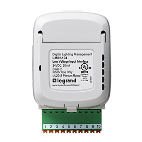
Catalog Number • Numéro de Catalogue • Número de Catálogo: LMIN-104
Country of Origin: Made in China • Pays d'origine: Fabriqué en Chine • País de origen: Hecho en China
LMIN-104-U is BAA and TAA compliant (Product produced in the U.S.)
This unit is pre-set for Plug n' Go™ operation,
adjustment is suggested.
For full operational details, adjustment and more features
of the product, see the DLM System Installation Guide
provided with Wattstopper room controllers, and also
available at www.legrand.us/wattstopper.
Installation shall be in accordance with all applicable
regulations, local and NEC codes. Wire connections shall
be rated suitable for the wire size (lead and building wiring)
employed.
For Class 2 DLM devices and device wiring: To be
connected to a Class 2 power source only. Do not reclassify
and install as Class 1, or Power and Lighting Wiring.
The LMIN-104 Digital Input Interface Module allows integration of 3rd party devices to the Wattstopper Digital Lighting Management
Local Network (DLM). The LMIN-104 connects to the DLM local network. In addition to On/Off control of loads, it can dim loads up and
down, or send messages such as After Hours, Shed, or Force On to the DLM local network based on external inputs.
The LMIN-104 operates on power from the DLM local network. It also provides input
terminal connections and options for converting input signals from 3rd party devices into
load controlling messages for the DLM system.
Four input terminals are provided for load control, group control, or generating DLM
scenario messages such as Force-ON, Force-OFF, load shedding, and cleaning functions.
Input terminals 1, 2, 3, and 4 are for connection of maintained or momentary switch closure
inputs, or third party logic inputs. Input signals may come from a wide variety of devices
including building automation systems, time clocks, and key switches.
By default, the LMIN-104 inputs accepts 2-wire momentary contacts to control DLM loads. If
2-wire maintained contracts, or 3-wire momentary contacts are needed, they can be set up
using LMCS software.
The LMIN-104 can also be changed via LMCS software so that it can be used as a partition
interface, for connection to an analog Wattstopper occupancy sensor, or for connection
to an remote photocell (functions previously performed by the LMIO-102, LMIO-201 and
LMIO-301 respectively).
NOTE: If an isolated low voltage relay is required, the LMOR-102 provides this functionality.
Using the LMIN-104 with LMCS
The LMIN-104 has three operating modes: Normal, Partition, and Photocell. By default it is set to Normal mode. LMCS-100 software
is required to select another mode. The mode is set for the entire LMIN-104—you can't have some inputs set to one mode and others
set to another.
While in Normal mode, you can choose between a Switch Input or Sensor Input. When using a switch input, seven Switch modes are
available, which determine the type of message sent to the DLM network. Again, switching selecting a value other than the default
requires LMCS. The available functions are: Load Control (the default, which switches Loads ON/OFF), Normal/After Hours, Load
Shed, Clean Switch, Force On, Force Off, and Key Switch.
If using a sensor input, the LMIN-104 can be used to control Loads or Scenes.
NOTE: In Normal mode, each input is independent and can be set to a different value. For example, you could use inputs 1 and 2 for
momentary switches, input 3 for a maintained switch, and input 4 for an occupancy sensor. However, since a 3 Wire Rocker
Dimmer switch uses two input wires, it requires use of either inputs 1 and 2, or 3 and 4. Therefore, when selecting that value for
input 1 or 3, the corresponding input 2 or 4 will be disabled in LMCS.
Wattstopper
DLM - Digital Input Interface Module
DLM – Module d'interface à entrée numérique
DLM: Módulo de interfaz de entrada digital
Installation Instructions • Instructions d'Installation • Instrucciones de Instalación
DESCRIPTION
OPERATION
®
SPECIFICATIONS
Voltage .................................................................24VDC
Current Consumption ............................................. 20mA
Power Supply ....................Wattstopper Room Controller
Connection to the DLM Local Network .......2 RJ-45 ports
Environment ....................................For Indoor Use Only
Operating Temperature ... 32° to 104°F (0° to 40°C)
Storage Temperature ..... 23° to 176°F (-5° to 80°C)
Relative Humidity ......... 5 to 95% (non condensing)
RoHS compliant, UL2043 Plenum rated
Patent Pending
Connect to
1
DLM local network
NOT Ethernet
2
3
4
Input 1
Input 2
Input 3
Input 4
+24VDC
Blue LEDs
LED 1
LED 2
LED 3
LED 4
24V Overload
Photocell In
GND
+24VDC
+24VDC
+24VDC
Table des Matières

Manuels Connexes pour LEGRAND Wattstopper


Sommaire des Matières pour LEGRAND Wattstopper
-
Page 8: Spécifications
Le module d’interface numérique LMIN-104 permet l’intégration de dispostifs de tierce partie au réseau local DLM (Digital Lighting Management) de Wattstopper. Le LMIN-104 se connecte au réseau DLM local. En plus de la mise en marche et d’arrêt du contrôleur de charges, il peut augmenter ou diminuer les charges ou envoyer des messages comme des messages Après les heures de travail (After... -
Page 9: Montage Et Câblage
La fenêtre du LMCS pour un LMIN-104 réglé en mode normal. MONTAGE ET CÂBLAGE ATTENTION : POUR CONNECTER UN ORDINATEUR AU RÉSEAU DLM LOCAL, UTILISER LE LMCI-100. NE BRANCHEZ JAMAIS LE RÉSEAU DLM LOCAL À UN PORT ETHERNET – CELA POURRAIT ENDOMMAGER LES ORDINATEURS AINSI QUE LES AUTRES ÉQUIPEMENTS CONNECTÉS. -
Page 10: Raccordement Des Connecteurs
LMIN-104 Appuyez à nouveau = la commande requise en envoyée, la DEL bleue correspondant à l’entrée est éteinte au LMIN-104 GMB tierce partie Détecteur de mouvement Wattstopper Cellule photoélectrique du détecteur (1) Entrée 1 (1) Entrée 1 Sortie du Sortie (2) Entrée 2... -
Page 11: Mode Normal
MODE NORMAL Interrupteur d’entrées Lorsque le système est en mode normal par défaut, le LMIN-104 prend implicitement pour valeur une entrée de type « interrupteur » et le mode d’interrupteur est réglé à « Contrôle de charge ». Ainsi réglé, un interrupteur basse tension n’étant pas sur le réseau DLM peut transformer toutes charges reliées à... - Page 12 Câblage pour l’entrée d’un détecteur BZ-150 Rouge Blanc Neutre Noir Rouge 120VCA Circuit 277VCA Câbles de basse tension Blue LEDs Connect to LED 1 DLM local network NOT Ethernet LED 2 Orange Gris LED 3 LED 4 Brun Bleu 24V Overload Contrôle Tout détecteur Commun...
-
Page 13: Exemples De Partition
EXEMPLES DE PARTITION Exemples de par Profil 1 0 mur (Pièce par défaut) Profil 1 Profil 2 1 mur (2 op ons) Profil 1 Profil 2 Profil 3 Profil 4 2 murs (4 op ons) Profil 1 Profil 2 Profil 3 3 murs (8 op ons) Profil 4... -
Page 14: Dépannage
MODE DE CELLULE PHOTOÉLECTRIQUE Le mode de cellule photoélectrique est une solution idéale pour toute application nécessitant un éclairage extérieur à contrôler selon les intensités d’éclairage d’un environnement extérieur comme un parc de stationnement, une installation ou un jardin éclairé. Les applications avec une grande quantité... - Page 22 (5) years. There are no obligations pour une période de cinq (5) ans. Wattstopper de obra por un período de cinco (5) años. No or liabilities on the part of Wattstopper for ne peut être tenu responsable de tout dommage...