Table des Matières
Publicité
Les langues disponibles
Les langues disponibles
Liens rapides
No: 24267 – 11/16 rev. 1
Catalog Numbers • Les Numéros de Catalogue • Números de Catálogo: EOSW-101,EOSW-102
Country of Origin: Made in China • Pays d'origine: Fabriqué en Chine • País de origen: Hecho en China
EOSW-101
This equipment has been tested and found to comply with the limits for a Class B digital device, pursuant to part 15 of the FCC rules.
These limits are designed to provide reasonable protection against harmful interference in a residential installation. This equipment
generates, uses and can radiate radio interference to radio communications. However, there is no guarantee that interference will not
occur in a particular installation.
If this equipment does cause harmful interference to radio or television reception, which can be determined by turning the equipment off
and on, the user is encouraged to try to correct the interference by one or more of the following measures:
• Reorient or relocate the receiving antenna. Increase the separation between the equipment and receiver.
• Connect the equipment into an outlet on a circuit different from that to which the receiver is connected.
• Consult the dealer or an experienced radio/TV technician for help.
The EOSW-101 and EOSW-102 Wall Switch Receivers are a one or two button switch that replaces a standard wall switch. It is the only
wired component of the system. The EOSW receivers receive signals from the Occupancy Sensor (EOPC) via radio frequency once
they are paired to the occupancy sensor.
NOTE: Pairing of devices should be done prior to binding and configurating loads. Pairing refers to establishing a link between two or
more devices for communication purposes. Binding refers to assigning a load to a specific button on a load controlling device
such as an EOSW. Please refer to the EOPC-100 Installation Instructions for PAIRING of sensor to EOSW-101/102 receivers.
Please refer to the EORS-10x/EOHR-10x Installation Instructions for PAIRING of the remote or handheld switches to the
EOSW-101/102 receivers.
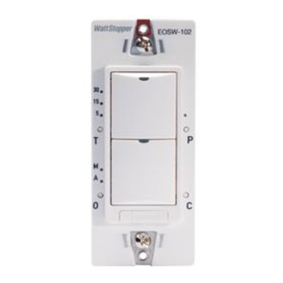
Time Delay: Three Green Time Delay LEDs on the left-side of
the switch display the selected time delay value of 30, 15 or 5
minutes. When a LED is ON, its corresponded value is active.
Each tap of the 'T' button cycles through the values.
Operating Mode: Two Green Operating Mode LEDs display the
selected operating mode. Each tap of the 'O' button alternates
between "Manual-On (M)" and "Automatic-On (A)".
Load Status: Each Load (Switch) Button has a Blue load status
LED. The LED is solid ON when the load paired to that button is
turned ON, and DIM when the load is OFF. Tap a Load (Switch)
Button to toggle loads ON/OFF.
Pairing Mode: One Green Pairing LED displays when in Pairing
mode. Each tap of the 'P' button cycles through the loads.
Configuration: Tap the 'C' button to enter configuration mode
and set load parameters on the receiver and assign buttons to
loads.
Air Gap Button: Press down to activate. Press the Air Gap Release button (left side) to deactivate.
Wattstopper
Wireless Lighting Control System EOSW Series Wall Switch Receivers
Système de contrôle de l'éclairage sans fil Récepteurs interrupteurs
muraux de la série EOSW
Sistema de control de iluminación inalámbrico Receptores con
interruptor de pared serie EOSW
Installation Instructions • Instructions d'Installation • Instrucciones de Instalación
EOSW-102
OPERATION
BUTTONS AND LED INDICATORS
Green Time Delay
LEDs (3)
Time Delay Button
Green Operating
Mode LEDs (2)
Operating Mode Button
®
SPECIFICATIONS
Input Voltage: ............................................ 120/277 VAC, 60 Hz
Load: ........................................................ 800W ballast @120V,
1200W fluorescent @277, 15W minimum for 120 VAC/60Hz,
30W minimum for 277 VAC/60Hz, LED driver, ELV, MLV, 1/6 HP
Time delay: ............................................ 5-30 minute adjustable
Connection to Wireless Network: ...............................................
Receives signals from Wireless Ceiling Sensor
(EOPC) and Remote Switch (EORS) via Radio Frequency
Environment ................................................For Indoor Use Only
Operating Temperature ................... 32° to 104°F (0° to 40°C)
Storage Temperature......................23° to 176°F (-5° to 80°C)
Relative Humidity ......................... 5 to 95% (non condensing)
Patent Pending
EOSW-101 Series
Air Gap Release
Button
1 Load Button Switch
EOSW-102 Series
Blue Load Status
LEDs
Load Button
Green Pairing LED
Pairing Button
Load Button
Configuration Button
Air Gap Button
2 Load Button Switches
Publicité
Table des Matières

Manuels Connexes pour LEGRAND Wattstopper EOSW Série


Sommaire des Matières pour LEGRAND Wattstopper EOSW Série
- Page 1 Wattstopper ® Wireless Lighting Control System EOSW Series Wall Switch Receivers Système de contrôle de l’éclairage sans fil Récepteurs interrupteurs muraux de la série EOSW Sistema de control de iluminación inalámbrico Receptores con No: 24267 – 11/16 rev. 1 interruptor de pared serie EOSW Installation Instructions •...
- Page 2 MOUNTING AND WIRING AIR GAP SWITCH FLUORESCENT LOAD SERVICING After connecting the load and line wires, secure the EOSW to the wallbox using the two screws that are IMPORTANT NOTE: ALWAYS ACTIVATE THE provided. Please, do not force or overtorque unit with AIRGAP SWITCH ON THE EOSW BEFORE torque screw driver.
- Page 3 SETTING LOAD PARAMETERS ON THE RECEIVER In Configuration mode, you can change the Time Delay “T”, Operation Mode “O”, or perform the load assignment or bind the loads. Step 1 Enter Configuration Mode EOSW-102 Series Press and Hold “Configuration” Button “C” for 3 Seconds “Load 1 Status”...
- Page 4 BINDING AND UNBINDING A SELECTED BUTTON FROM A RECEIVER LOAD By default the Wall Switch buttons are bound to the loads. On a single button switch, the button will be EOSW-102 Series bound to the wired load. On a two button switch, the top button #1 will be bound with Load #1, and the “Load 1 Status”...
-
Page 5: Caractéristiques
INSTRUCTIONS EN FRANÇAIS Cet appareil a été testé et a prouvé qu'il était conforme aux limites CARACTÉRISTIQUES prévues pour un appareil numérique de Classe B conformément à la partie 15 des réglementations de la FCC. Ces limites sont Tension d’entrée: ..........120/277 V c.a., 60 Hz conçues pour fournir une protection satisfaisante contre les Load (Charge): ..........Ballast 800 W à... -
Page 6: Montage Et Câblage
MONTAGE ET CÂBLAGE INTERRUPTEUR À INTERVALLE D'AIR - ENTRETIEN D'UNE CHARGE FLUORESCENTE Après avoir raccordé les fils de charge et de circuit, fixez l’EOSW sur son boîtier mural à l’aide des deux vis fournies. Veuillez ne REMARQUE IMPORTANTE : ACTIVEZ pas forcer ou serrer excessivement le dispositif avec le tournevis TOUJOURS L'INTERRUPTEUR dynamométrique. -
Page 7: Rétablir Les Paramètres Par Défaut Des Unités
RÉGLAGES DES PARAMÈTRES DE CHARGE SUR LE RÉCEPTEUR (A CONTINUÉ) Étape 2 modifier la « temporisation » EOSW-102 Appuyez sur le bouton « temporisation » « T » pour faire défiler les options DELs bleu DELs de « état de la charge » de durée, 30 min/15 min/5 min, par ordre décroissant. -
Page 8: Dépannage
ASSOCIER ET DISSOCIER UN BOUTON SÉLECTIONNÉ D'UNE CHARGE DU RÉCEPTEUR Par défaut, les boutons de l'interrupteur mural sont associés aux charges. Sur un interrupteur Série EOSW-102 à un bouton, le bouton sera associé à la charge câblée. Sur un interrupteur à deux boutons, DEL bleu «... - Page 9 INSTRUCCIONES EN ESPAÑOL Este equipo ha sido probado y cumple con los límites de ESPECIFICACIONES dispositivos digitales clase B, de acuerdo con la parte 15 de las reglas de la FCC. Estos límites están diseñados para ofrecer Voltaje de entrada: ..........120/277 V CA, 60 Hz una protección razonable contra la interferencia nociva en una Carga: .............Balasto de 800 W a 120 V, instalación residencial.
-
Page 10: Montaje Y Cableado
MONTAJE Y CABLEADO INTERRUPTOR DE ESPACIO DE AIRE - MANTENIMIENTO DE LAS CARGAS FLUORESCENTES Después de conectar los cables de carga y de línea, fije el EOSW a la caja de pared con los dos tornillos provistos. No fuerce ni ajuste en exceso la unidad con el destornillador. - Page 11 ESTABLECER LOS PARÁMETROS DE CARGA EN EL RECEPTOR (CONTINUADO) Step 2 Modificar el tiempo de demora “Time Delay” EOSW-102 LEDs de Toque el botón de tiempo de retardo ("T") para alternar entre las opciones de 30, 15 LEDs azules de tiempo de estado de la carga y 5 minutos en orden descendente.
-
Page 12: Solución De Problemas
No. 24267 – 11/16 rev. 1 © Copyright 2016 Legrand All Rights Reserved. 800.879.8585 © Copyright 2016 Tous droits réservés Legrand. www.legrand.us/wattstopper © Copyright 2016 Legrand Todos los derechos reservados.