
Manuels Connexes pour Schick Dental Profi

Sommaire des Matières pour Schick Dental Profi
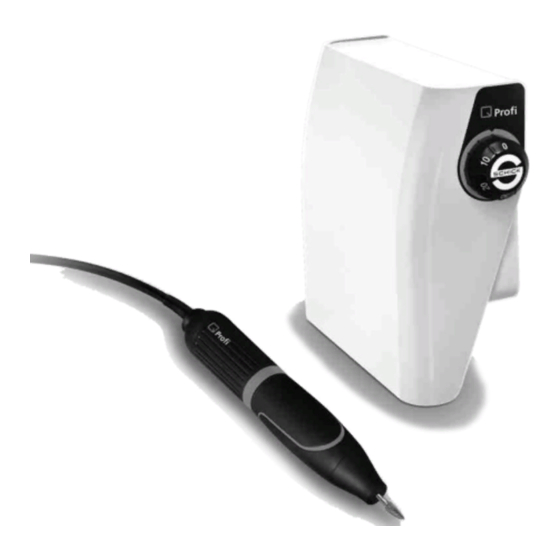
- Page 1 Original Betriebsanleitung Operating Instructions Mode d‘emploi Istruzioni per l‘uso Instrucciones de uso...
-
Page 2: Table Des Matières
Wir freuen uns, dass Sie sich für ein technisch hochwertiges Gerät aus dem Hause SCHICK entschieden haben und wünschen Ihnen mit Ihrem neuen - Antriebsgerät viel Erfolg und Freude beim Arbeiten. Wir haben diese Betriebsanleitung zusammengestellt, um Sie mit Ihrem neuen Gerät vertraut zu machen und Ihnen die notwendigen Hinweise für Bedienung und Wartung zu geben. -
Page 3: Sicherheitshinweise
1. Sicherheitshinweise 1.1 Prüfen, ob Netzdaten mit den Angaben auf dem Typenschild übereinstimmen. 1.2 Die Anlagen sind nicht für folgenden Einsatz bestimmt: - in explosionsgefährdeter Umgebung - für medizinische Anwendungen - Bearbeitung feuchter Werkstoffe 1.3 Bei Benutzung sind die einschlägigen Bestimmungen der Berufsgenossenschaft zu beachten: - stets Schutzgläser benutzen - für ausreichende Beleuchtung sorgen - Absaugung benutzen... -
Page 4: Übersicht Lieferumfang
3. Übersicht - Lieferumfang (5a) (5b) Art.Nr. Fußversion Knieversion: Art.Nr.: SK komplett 9340/5 SF komplett 9350/5 Steuergerät Knieausführung 9345/5 Steuergerät Fußausführung 9355/5 9300 Motorhandstück mit Kabel Motorhandstück mit Kabel 9300 Handstückablage 9127 Handstückablage 9127 mit 2 Werkzeugen mit 2 Werkzeugen (5a) Netzteil... -
Page 5: Zubehör/Optionales
4. Zubehör/Optionales 6642 Spannzange Ø 2,35mm 4115 Spannzangenschlüssel 6223 Gegenschlüssel 9225 Ersatzmotorkabel Niethammer Doppelniethammer Niethammer mit Meißelaufsatz Art.-Nr. 1850 Art-Nr. 1850/1 Art.-Nr. 1860... -
Page 6: Inbetriebnahme Und Montage
5. Inbetriebnahme und Montage 5.1 Montage der Aufhängeleiste für das Kniesteuergerät 1. Die Aufhängeleiste (7) ist mit Hilfsteilen versehen, die als Anschlag zur korrekten Positionierung des Kniesteuergerätes dienen. Hierzu ist die Aufhängeleiste entsprechend der Abb.1 am Arbeitstisch zu positionieren und mittels der beigefügten Schrauben (8) zu befestigen. Nach der Montage können die drei Hilfsteile einfach von der Aufhängeleiste abgebrochen werden. - Page 7 5.3 Inbetriebnahme Schließen Sie das Motorhandstück an die Buchse „Motorhandstück 1" an. Stecken Sie den Stecker des Netzadapters in die Stromversorgungsbuchse des Steuergerätes. Verbinden Sie das Netzkabel (6) mit dem Netzteil (5a). Zum Einschalten des Gerätes muss das Bedienelement (Knieplatte, Fußhebel) einmal betätigt werden. Servicebuchse Signal für Absaugung...
-
Page 8: Werkzeugwechsel
6. Werkzeugwechsel am Motorhandstück Hier festhalten Durch Drehen des Griffmantels am Handstück kann die Spannzange geöffnet bzw. geschlossen werden. Werkzeugwechsel nur bei ausgeschaltetem Motor! Im Hinblick auf Genauigkeit und Lebensdauer der Spannzange muss - auch bei Nichtbetrieb - immer ein Werkzeug oder der werkseitig mitgelieferte Schutzstift eingespannt sein. -
Page 9: Reinigung Und Wartung/Spannzangenwechsel
8. Reinigung und Wartung/Spannzangenwechsel Das Motorhandstück ist auf maximale Haltbarkeit ausgelegt, dennoch sollte von Zeit zu Zeit die Spannzange ausgebaut und gereinigt werden, sowie der sich unter der Handstückspitze befindliche Schmutz entfernt werden. 8.1 Ausbau der Spannzange beim Handstück 6662/1 6653/1... -
Page 10: Störungen
9. Störungen Wird das Handstück überlastet bzw. blockiert, schaltet das Gerät aus Sicherheitsgründen ab. Knieplatte oder Fußhebel in die 0-Position bringen und wieder neu betätigen; das Gerät ist dann sofort wieder einsatzbereit. Lässt sich eine Störung nicht mittels obiger Beschreibung beheben, wenden Sie sich bitte an einen autorisierten Servicepartner oder die Firma Schick direkt. -
Page 11: Konformitätserklärung
11. Konformitätserklärung Wir, die SCHICK GmbH Lehenkreuzweg 12 D-88433 Schemmerhofen erklären hiermit, dass das Produkt - Anlagen bestehend aus - Motorhandstück 9300 in Verbindung mit - Steuergerät 9345/5 oder 9355/5 Netzteil 9102 und Signalgeber 9060 folgenden einschlägigen Bestimmungen entspricht: 2006/42/EG (Maschinenrichtlinie) 2014/30/EU... - Page 12 D21429 02/17 gz...
- Page 13 English Original Operating Instructions...
- Page 14 We are pleased that you decided to buy a highly developed piece of equipment from SCHICK and would like to wish you every success when working with your new We wrote these operating instructions to enable you to get accustomed to your new piece of equipment and to provide you with the correct operating and...
-
Page 15: Safety Information
1. Safety information 1.1 Ascertain that your mains supply coincides with the data on the rating plate. units are not suitable for the following applications: - in areas where there is a risk of explosion - for medical applications - for working on moist materials 1.3 Ensure that all regulatory requirements are observed during use - always wear protective glasses... -
Page 16: Summary List Of Contents
3. Summary - List of contents (5a) (5b) kneeversion: Art.Nr. foot control: Art.Nr.: SK complete 9340/5 SF complete 9350/5 knee controller 9345/5 foot controller 9355/5 motorhandpiece with cable 9300 motorhandpiece with cable 9300 9127 handpiecerack handpiecerack 9127 with two keys for changing the chuck with two keys for changing the chuck... - Page 17 4. Accessories/optionals 6642 chuck Ø 2,35mm 4115 chuck key 6223 counterstay wrench 9225 motor cable complete riveting hammer twin riveting hammer riveting hammer with chisel Art.no. 1850 Art.no. 1860 Art.no. 1850/1...
-
Page 18: Initial Start Up And Installation
5. Initial start-up and installation 5.1 Installation of the suspension strip for knee control unit or work bench control unit 1 The suspension strip (7) is supplied with a template which acts as an aid for correct positioning of knee control unit. -
Page 19: Initial Start-Up
5.3 Initial start-up Connect the network cable (6) to the power supply (5a). Connect the motorhandpiece to the 'motorhandpiece 1 'socket. Plug the network adaptor into the power supply socket on the control unit. To switch on the device, activate the operating component (knee pad, foot lever, etc.) once. serviceplug signal for suction power supply... -
Page 20: Tool Change On Motorhandpiece
6. Tool change on motorhandpiece Hold firmly here close open By turning the gripsleeve on the handpiece, the chuck can be opened or closed. Only carry out a tool change when the motor is switched off! To optimise the precision and durability of the chuck, the tool or the factory-supplied protective pin must always be in a fixed position, even when not in use. -
Page 21: Removing The Chuck
8. Cleaning and Maintenance / Removing the chuck The motor handpiece is designed for maximum durability and therefore, the chuck and the tip should be removed and cleaned from time to time. 8.1 Removal of chuck on the motorhandpiece 6662/1 6653/1... -
Page 22: Errors
9. Errors If the handpiece is overloaded or blocked, the control unit switches off automatically to prevent futher damadges. Make sure the tool can rotate freely in the handpiece and after releasing foot lever or knee lever back to neutral position the unit can continue operation. If an error cannot be removed following the above description, please contact an authorised service partner or Schick directly. -
Page 23: Declaration Of Conformity
11. Declaration of Conformity We, the SCHICK GmbH Lehenkreuzweg 12 D-88433 Schemmerhofen declare herewith, that the products - consisting of - handpiece 9300 in combination with - control unit 9345/5 or 9355/5 power supply 9102 and pulse emitter for suction 9060 are in conformity with the following provisions of Directive: 2006/42/EG (machinery directive) - Page 24 02/17 gz D21429...
- Page 25 Français Originale Mode d‘emploi...
- Page 26 Nous nous réjouissons de votre décision d'utiliser un appareil de haute technicité de la société SCHICK et nous vous souhaitons, avec votre nouvelle pièce à main beaucoup de satisfications dans votre travail. Nous avons rédigé ce mode d'emploi pour vous familiariser avec votre nouvel appareil et pour vous fournir les informations nécessaires pour l'utilisation et l'entretien de celui-ci.
-
Page 27: Indication De Sécurité
1. Indication de sécurité 1.1 Vérifier si les données du réseau concordent avec celles de la plaquette signalétique. 1.2 Les moteurs ne doivent pas être utilisés: - en cas de danger d'explosion - pour le traitement médical - pour usiner des matériaux humides 1.3 Respecter les prescriptions professionelles propres à... -
Page 28: Contenu Livré
3. Contenu livré (5a) (5b) Appareil de commande actionné Appareil de commande actionné no. d‘article avec le genou: avec le pied: no. d‘article SK complet 9340/5 SF complet 9350/5 appareil de commande actionné appareil de commande actionné avec le genou: 9345/5 avec le pied:... -
Page 29: Accessoires/Pièces De Rechange
4. Accessoires/pièces de rechange pince de serrage Ø 2,35mm 6642 clé p. pince de serrage 4115 clé plate 6223 cordon 9225 burin double-burin burin no. d‘article 1850 no. d‘article 1860 no. d‘article 1850/1... -
Page 30: Mise En Service Et Montage
5. Mise en service et montage 5.1 Montage du liteau de suspension pour l'appareil de commande au genou 1. Le liteau de suspension (7) est muni de pièces auxiliaires qui servent de butée pour un positionnement correct de l'appareil de commande au genou . -
Page 31: Mise En Service
5.3 Mise en service Raccordez la prise de la pièce à main à la fiche du boitier de commande „pièce à main 1". Connectez la fiche de l‘adaptateur réseau dans la douille de l‘alimentation électrique de l‘appareil le commande. Reliez le câble de réseau (6) à l‘adaptateur rése au (5a). Pour mettre en marche l‘appareil, actionnez d‘abord l‘élément de commande (variateur avec le genou/le pied). -
Page 32: Changement D'instrument Sur La Pièce À Main Moteur
6. Changement d‘instrument sur la pièce à main moteur fermé tenir ici ouvert La pince de serrage est ouverte ou fermée en tournant l'extrémité de la pièce à main. Ne changer l'instrument que lorsque le moteur est à l'arrêt! Pour conserver la précision et préserver la durée de vie de la pince de serrage, elle doit toujours être munie d'un instrument ou de la pointe de protection fournie à... -
Page 33: Nettoyage Et Entretien/Changement De La Pince De Serrage
Nettoyage et entretien/Changement de la pince de serrage La pièce à main est conçue pour une longévité maximale, mais il est nécessaire de démonter de temps en temps la pince de serrage et de la nettoyer. 8.1 Démontage de la pince de serrage pièce à main 6662/1 6653/1 9225... -
Page 34: Possibles Messages D'erreur
9. Possibles messages d‘erreur Si la pièce à main est surchargée ou bloquée, le moteur s'arrête pour des raisons de sécurité. En lâchant l'élément de commande (variateur avec le genou/pédale) et en l’actionnant de nouveau, l'appareil est immédiatement prêt à fonctionner. Si la perturbation ne peut être réparée à... - Page 35 11. Declaration of Conformity We, the SCHICK GmbH Lehenkreuzweg 12 D-88433 Schemmerhofen declare herewith, that the products - consisting of - handpiece 9300 in combination with - control unit 9345/5 or 9355/5 power supply 9102 and pulse emitter for suction 9060 are in conformity with the following provisions of Directive: 2006/42/EG (machinery directive)
- Page 36 02/17 gz D21429...
- Page 37 Italiano Originale Istruzioni per l‘uso...
- Page 38 Complimenti per la Sua scelta di un apparecchio di elevate qualità tecniche della SCHICK, e le auguriamo successo e soddisfazione nel suo lavoro con il dispositivo di comando Queste istruzioni per l‘uso sono state concepite per facilitarle la conoscenza dell‘apparecchio, e per darle le necessarie informazioni per l‘uso e per la manutenzione.
-
Page 39: Informazioni Di Sicurezza
1. Informazioni di sicurezza 1.1 Controllare se la tensione di rete corrisponde a quella indicata sulla targhetta dell’apparecchio. 1.2 Gil apparecchi non devono essere usati nei casi di: - ambienti a pericolo di esplosione - sui pazienti - lavorazione di materiali umidi 1.3 Durante la lavorazione osservare le regole di prevenzione degli infortuni: - uso continuo di occhiali di protezione - ottimale illuminazione del posto di lavoro... -
Page 40: Corredo Di Base
3. Corredo di base (5a) (5b) modello con comando a ginoccio: cod. art. modello con comando a pedale: cod.art. 9340/5 SF del tutto SK del tutto 9350/5 modello con comando a ginoccio 9345/5 modello con comando a pedale 9355/5 Manipolo a motore con cavol 9300... - Page 41 4. Accessori pinza portante Ø 2,35mm 6642 pinza di serragio 4115 chiave a forchetta 6223 cavo di ricambo per il motore 9225 Martello per rivetare Martello per rivetare Martelo per rivetare cod. art. 1850 cod. art. 1860 cod. art. 1850/1...
-
Page 42: Installazione E Montaggio
5. Installazione e montaggio 5.1 Montaggio della placca di sospensione per il dispositivo di comando a ginocchio o da tavolo 1. La placca di sospensione (7) è dotata di listelli ausiliari che fungono da dispositivi d'arresto per il corretto posizionamento del dispositivo di comando a ginocchio. La placca deve essere posizionata in corrispondenza del piano di lavoro come descritto in Fig. -
Page 43: Messa In Funzione
5.3 Messa in funzione Collegare il manipolo a motore alla presa „Motorhandstück 1” (manipolo a motore 1). Inserire la spina dell'adattatore di rete nella presa di alimentazione del dispositivo di comando. Collegare il cavo di rete (6) all'alimentatore (5a). Per accendere il dispositivo è necessario azionare una volta l'elemento di comando (piastra per ginocchio/pedale). -
Page 44: Sostituzione Dell'utensile
6. Sostituzione dell'utensile sul manipolo elettrico tenere fermo qui chiuso aperto Ruotando il rivestimento dell'impugnatura del manipolo è possibile aprire o chiudere la pinza di serraggio. Sostituire l'utensile esclusivamente a motore spento! Per una maggiore precisione e durata della pinza di serraggio, anche quando il manipolo non è... -
Page 45: Pulizia E Manutenzione/Cambio Della Pinza Portante
8. Pulizia e manutenzione/Cambio della pinza portante Il manipolo a motore è progettato per la massima durata, tuttavia di quando in quando è necessario smontare e pulire la pinza di serraggio. 8.1 Smontaggio della pinza di serraggio 6662/1 6653/1 9225 6652 (2,35mm) -
Page 46: Disturbi
9. Disturbi Se il manipolo è sovraccarico o bloccato, il dispositivo si spegne per motivi di sicurezza. Portare la piastra per ginocchio o il pedale nella posizione 0 e toccare nuovamente l’elemento di comando; il dispositivo è di nuovo pronto per l’uso. Qualora non sia possibile risolvere il problema mediante le istruzioni riportate sopra, contattare uno dei partner per l’assistenza autorizzati o direttamente l'azienda Schick. - Page 47 11. Declaration of Conformity We, the SCHICK GmbH Lehenkreuzweg 12 D-88433 Schemmerhofen declare herewith, that the products - consisting of - handpiece 9300 in combination with - control unit 9345/5 or 9355/5 power supply 9102 and pulse emitter for suction 9060 are in conformity with the following provisions of Directive: 2006/42/EG (machinery directive)
- Page 48 02/17 gz D21429...
- Page 49 Español Original Instrucciones de uso...
- Page 50 Nos es grato constatar su decisión por un aparato de la casa SCHICK de alta calidad técnica. Y le deseamos mucho éxito y un trabajo agradable con su nuevo motor Hemos redactado estas instrucciones de uso para familiarizarle con su nuevo aparato y proporcionarle los consejos necesarios para su manejo y mantenimiento.
-
Page 51: Informaciones De Seguridad
1. Informaciones de seguridad 1.1 Controlar que la tensión de la red coincida con las indicaciones sobre la placa de especificaciones. 1.2 Los equipos no están concebidos para el siguiente uso: - en ambientes con peligro de explosión - en pacientes - trabajo con materiales húmedos 1.3 Para su utilización deben observarse siempre las pertinentes normas del gremio profesional: -utilizar siempre gafas protectoras... -
Page 52: Relación De Los Modelos
Relación de los modelos (5a) (5b) versión rodilla: versión de pie: No. de ref. No. de ref. completo 9350/5 9340/5 SF completo caja de mando versión rodilla 9355/5 9345/5 caja de mando versión de pie pieza de mano con cable 9300 9300 pieza de mano con cable... -
Page 53: Relación De Los Modelos Y Sus Componentes
Relación de los modelos y s us componentes 6642 pinza Ø 2,35mm 4115 llave 6223 contra-llave 9225 cable martillo solo martillo con el cincel martillo doble No. de ref. 1850 No. de ref. 1850/1 No. de ref. 1850/2... -
Page 54: Puesta En Servicio
5. Puesta en servicio y montaje Montaje de la placa delantera colgante para el dispositivo de control con la rodilla Fig.1 Fig.2 . 1. La placa delantera (7) colgante está provista de partes auxiliares que sirven como ayuda para la colocación correcta del dispositivo de control con la rodilla . -
Page 55: Puesta En Servicio
5.3 Puesta en servicio Conecte la pieza de mano al conector “Pieza de mano 1“. Enchufe el conector del adaptador de alimentación en el enchufe eléctrico del dispositivo de control. Conecte el cable de alimentación (6) con el adaptador de corriente (5a). Para encender el aparato tiene que accionar el elemento de control (placa de rodilla, pedal) una vez. -
Page 56: Cambio De Herramientas En La Pieza De Mano
6. Cambio de herramientas en la pieza de mano cerrar Mantenga aqui abrir Al girar el tubo del mango de agarre de la pieza de mano, la pinza de ajuste puede abrirse o cerrarse. ¡Realizar el cambio de la herramienta sólo cuando el motor esté apagado! En cuestión de precisión y durabilidad de la pinza - aun cuando no esté... -
Page 57: Limpieza Y Mantenimiento
8. Limpieza y mantenimiento La pieza de mano está diseñado para una máxima durabilidad, pero usted debe sacar la pinza y limpiarla de vez en cuando. 8.1 Cómo sacar la pinza de la pieza de mano 6662/1 6653/1 9225 6652 (2,35mm) 6652/1 (3,00mm) 6642 (2,35mm) -
Page 58: Fallos
9. Fallos Si se sobrecarga o bloquea la pieza de mano, el aparato se desconecta por razones de seguridad. Poner la placa de rodilla o el pedal en la posición 0 y volver a accionar; el aparato vuelve a estar disponible inmediatamente. Si no se puede solucionar el fallo con el método descrito arriba, diríjase a un servicio técnico autorizado o directamente a la empresa Schick. - Page 59 11. Declaration of Conformity We, the SCHICK GmbH Lehenkreuzweg 12 D-88433 Schemmerhofen declare herewith, that the products - consisting of - handpiece 9300 in combination with - control unit 9345/5 or 9355/5 power supply 9102 and pulse emitter for suction 9060 are in conformity with the following provisions of Directive: 2006/42/EG (machinery directive)
- Page 60 D21429 02/17 gz...