
Manuels Connexes pour ESAB Precision Plasmarc EPP-450

Sommaire des Matières pour ESAB Precision Plasmarc EPP-450
- Page 1 Source d’énergie pour découpe au plasma EPP-450 Manuel d’instructions - FR 0558007949 08/2014...
- Page 2 ASSUREZ-VOUS QUE CETTE INFORMATION EST DISTRIBUÉE À L'OPÉRATEUR. VOUS POUVEZ OBTENIR DES COPIES SUPPLÉMENTAIRES CHEZ VOTRE FOURNISSEUR. ATTENTION Les INSTRUCTIONS suivantes sont destinées aux opérateurs qualifiés seulement. Si vous n’avez pas une connaissance approfondie des principes de fonctionnement et des règles de sécurité...
-
Page 5: Table Des Matières
TABLE DES MATIÈRES Section / Titre Page Mesures de sécurité ................. . .7 Description . -
Page 6: Section / Titre
TABLE DES MATIÈRES Section / Titre Page Dépannage ..................37 6.1 Généralités. - Page 7 PRÉCAUTIONS DE SÉCURITÉ Précautions de sécurité Les utilisateurs du matériel de soudage et de coupage plasma ESAB ont la responsabilité ultime d'assurer que toute personne qui opère ou qui se trouve dans l'aire de travail observe les précautions de sécurité pertinentes. Les précautions de sécurité...
-
Page 8: Mesures De Sécurité
SECTION 1 PRÉCAUTIONS DE SÉCURITÉ LE SOUDAGE ET LE COUPAGE À L'ARC PEUVENT CAUSER DES BLESSURES À L'OPÉRATEUR OU LES AUTRES PERSONNES SE TROUVANT DANS L'AIRE DE TRAVAIL. ASSUREZ-VOUS AVERTISSEMENT DE PRENDRE TOUTES LES PRÉCAUTIONS NÉCESSAIRES LORS D'UNE OPÉRATION DE SOUDAGE OU DE COUPAGE. DEMANDEZ À... -
Page 9: Description
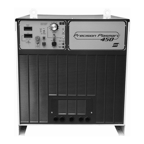
La source d’énergie de l’EPP est conçue pour des applications mécanisées de marquage et de découpe au plas- ma à haut débit. Elle peut être utilisée avec d’autres produits ESAB tels que les torches PT-15, PT-19XLS, PT-600 et PT-36, ainsi qu’avec le système informatisé régulateur de gaz et de commutation Smart Flow II. -
Page 10: Poids Et Dimensions
SECTION 2 DESCRIPTION Poids et dimensions 1143 mm 946 mm 45 po. 37,25 po 1022 mm 40,25 po Poids = 850 kg (1870 livres) -
Page 11: Installation
SECTION 3 INSTALLATION 3.1 Généralités LE NON RESPECT DES INSTRUCTIONS PEUT ENTRAÎNER LA MORT, DES BLESSURES CORPORELLES OU DES DÉGÂTS MATÉRIELS. SUIVEZ CES INSTRUCTIONS POUR ÉVITER TOUTE BLESSURE OU TOUT DOM- DANGER MAGE MATÉRIEL. VEILLEZ À BIEN RESPECTER LES CODES DE SÉCU- RITÉ... -
Page 12: Branchement De L'alimentation
SECTION 3 INSTALLATION 3.4 Branchement de l’alimentation TOUTE DÉCHARGE ÉLECTRIQUE PEUT ÊTRE MORTELLE ! ASSUREZ UNE PROTECTION MAXIMUM CONTRE LES ÉLECTROCU- DANGER TIONS. AVANT DE PROCÉDER À UNE CONNEXION QUELCONQUE À L’INTÉ- RIEUR DE LA MACHINE, OUVREZ LE COUPE-CIRCUIT MURAL POUR COUPER L’ALIMENTATION. -
Page 13: Conducteurs D'entrée
SECTION 3 INSTALLATION 3.4.2 Conducteurs d’entrée • Fourni par le client • Peut être composé de conducteurs en cuivre recouverts d’un épais caoutchouc (3 pour l’alimentation et 1 pour la prise de terre) ou passer par une conduite rigide ou flexible. •... -
Page 14: Branchements De Sortie
SECTION 3 INSTALLATION TOUTE DÉCHARGE ÉLECTRIQUE PEUT ÊTRE MORTELLE ! VÉRIFIEZ DE LAISSER UN ESPACE ENTRE LES BORNES À BAGUE, LE DANGER PANNEAU LATÉRAL ET LE TRANSFORMATEUR PRINCIPAL. CET ESPA- CE DOIT ÊTRE SUFFISANT POUR ÉVITER TOUT ARC ÉLECTRIQUE ÉVEN- TUEL. -
Page 15: Installation En Parallèle
SECTION 3 INSTALLATION Ouvrir le panneau d’accès EPP-401/450 Alimentation Pièce de travail électrode(-) * 2 fils en parallèle 2/0 AWG 600 V sont conseillés pour arc pilote un fonctionnement à 100 % de la capacité en 450 A. Pour un fonctionnement à 100 % de la capacité jusqu’à 400 A, un fil de 4/0 peut être utilisé. -
Page 16: Branchements Pour L'installation De Deux Sources D'énergie Epp-401/450 En Parallèle
SECTION 3 INSTALLATION 3.6.1 Branchements pour l’installation de deux sources d’énergie EPP-401/450 en parallèle Remarque : Le conducteur de l’électrode (-) de la source d’alimentation principale est équipé d’un cavalier. Le câble de masse (+) de la source d’alimentation auxiliaire est également équipé d’un cavalier. 1. - Page 17 SECTION 3 INSTALLATION Branchements pour l’installation de deux sources d’alimentation EPP-401/450 en parallèle fonctionnant simul- tanément. Les connexions ci-dessous conviennent à un fonctionnement en parallèle jusqu’à 800 A à 100 % de capacité ou 900 A jusqu’à 80 % de capacité. 80 % de capacité signifie 8 minutes de fonctionnement de l’arc toutes les 10 minutes.
- Page 18 SECTION 3 INSTALLATION 3.6.1 Branchements pour l’installation de deux sources d’énergie EPP-401/450 en parallèle (sui- Branchements pour l’installation de deux sources d’alimentation EPP-401/450 en parallèle fonctionnant succes- sivement. Les connexions pour un fonctionnement en alimentation unique jusqu’à 400 A à 100 % de capacité ou 450 A jusqu’à...
-
Page 19: Marquage Avec Deux Epp-401/450 En Parallèle
SECTION 3 INSTALLATION 3.6.1 Branchements pour l’installation de deux sources d’énergie EPP-401/450 en parallèle (sui- Branchements pour l’installation de deux sources d’alimentation EPP-401/450 en parallèle fonctionnant succes- sivement. Les connexions ci-dessous conviennent à un fonctionnement en alimentation unique jusqu’à 450 A jusqu’à 100 % de capacité. -
Page 20: Câbles D'interface
SECTION 3 INSTALLATION 3.6.2 Marquage avec deux EPP-401/450 en parallèle (suite) FONCTIONNEMENT DE DEUX EPP-401/450 EN PARALLÈLE : Fournir les commandes de Marche/Arrêt, de Découpe/Marquage et les signaux d’amplitude Haute/Basse du courant aux unités d’alimentation principale et auxiliaire. Alimentez le même signal V aux deux sources d’énergie. -
Page 21: Câbles D'interface Cnc Avec Connecteur D'alimentation Homologue Et
SECTION 3 INSTALLATION 3.7.1 Câbles d’interface CNC avec connecteur d’alimentation homologue et interface CNC non terminée Connecteur mâle Réf. : 647032 VERT/JAU ROUGE n°4 3.7.2 Câbles d’interface CNC avec connecteurs d’alimentation et connecteur CNC homologues Connecteur mâle Connecteur CNC Réf. : 647032 Réf. -
Page 22: À Chaque Extrémité
SECTION 3 INSTALLATION 3.7.3 Câbles d’interface de refroidisseur d’eau avec connecteurs d’alimentation homologues à chaque extrémité Connecteur femelle Connecteur mâle Réf. : 2062105 Réf. : 647257... -
Page 23: Fonctionnement
SECTION 4 FONCTIONNEMENT Description des circuits du schéma fonctionnel... -
Page 24: Description Des Circuits Du Schéma Fonctionnel (Suite)
à rallonger la durée de vie des consommables. Le graphique ci-dessous illustre les effets du système ESAB breveté de réduction des ondulations à l’aide de deux relais modulateurs synchronisés agissant successivement comme interrupteurs. Comparez ces résultats à ceux obtenus par deux relais fonctionnant simultanément, la méthode successive permet généralement de réduire les ondulations de 4 à... - Page 25 SECTION 4 FONCTIONNEMENT 4.1 Description des circuits du schéma fonctionnel (suite) Le schéma fonctionnel de l’EPP-401/450 (suivant la sous-section 4.1) illustre les principaux éléments fonctionnels de la source d’alimentation. Le transformateur principal (T1) offre une isolation de la ligne principale d’alimentation ainsi que la tension appropriée au bus c.c.
-
Page 26: Panneau De Commande
SECTION 4 FONCTIONNEMENT 4.2 Panneau de commande A - Alimentation principale Le témoin s’allume lorsque la source d’alimentation est mise sous tension. B - Contacteur allumé Le témoin s’allume lorsque le contacteur principal est mis sous tension. C - Surchauffe Le témoin s’allume en cas de surchauffe de la source d’alimentation. -
Page 27: Panneau De Commande (Suite)
SECTION 4 FONCTIONNEMENT 4.2 Panneau de commande (suite) H et L - Connexions à distance H - Connecteur à 24 broches pour brancher l’alimentation au CNC (commande à distance) L - Connecteur à 8 broches pour brancher l’alimentation au circulateur de liquide de refroidissement I - Commutateur HIGH / LOW (Haute/Faible) de l’arc pilote Utilisé... - Page 28 SECTION 4 FONCTIONNEMENT 4.2 Panneau de commande (suite) J - Jauges Affiche la tension et l’intensité lors de la découpe. L’ampèremètre peut être activé avec le bouton <Actual / Preset> (Effectif/Prédéfini) avant la découpe pour afficher une estimation du courant de découpe nécessaire. K - Commutateur Actual/Preset (Effectif/Prédéfini) Le commutateur à...
-
Page 29: Modes De Fonctionnement : Modes De Découpe Et De Marquage Avec Courant Élevé (Hi) Ou Faible (Low)
SECTION 4 FONCTIONNEMENT 4.2.1 Modes de fonctionnement : modes de découpe et de marquage avec courant élevé (HI) ou faible (LOW) L’EPP-401/450 fonctionne en mode de découpe en deux amplitudes de courant. L’amplitude de courant à faible intensité se situe entre 35 et 100 A qui correspond au signal V de 3,50 à... -
Page 30: Séquence Du Fonctionnement
SECTION 4 FONCTIONNEMENT 4.3 Séquence du fonctionnement SECTION 4 Operation 4.3 Sequence of Operation SECTION 4 Operation 1. Apply power by closing the line (wall) switch. Apply Power Mettez sous tension en fermant l’interrupteur mural de la ligne. (The ESP-400C does not have an on/off (L’EPP-401/450 n’est pas équipé... -
Page 31: Paramètres De L'amorçage De L'arc
SECTION 4 FONCTIONNEMENT 4.4 Paramètres de l’amorçage de l’arc La durée d’obtention d’intensité maximale peut être réglée pour un démarrage en douceur. Cette fonctionnalité utilise une intensité réduite pour le démarrage qui augmente progressivement jusqu’à l’intensité maximale. L’EPP-401/450 est livré avec cette fonction activée. -
Page 32: Conditions D'activation / Désactivation De L'amorçage De L'arc
SECTION 4 FONCTIONNEMENT 4.4.1 Conditions d’activation / désactivation de l’amorçage de l’arc Paramètre d’usine par défaut illustré. allumé éteint 1. Retirez le panneau d’accès sur le coin droit supérieur du panneau avant. Assurez-vous de remettre en place ce panneau une fois tous les réglages terminés. 2. -
Page 33: Commandes De L'amorçage De L'arc
SECTION 4 FONCTIONNEMENT 4.4.4 Commandes de l’amorçage de l’arc Potentiomètre de courant Minuteur de croissance de démarrage 4.4.5 Courant de démarrage et minuteur de croissance Rapport entre le courant de démarrage (%) et le réglage du potentiomètre Courant de démarrage Réglez à... - Page 34 SECTION 4 FONCTIONNEMENT 4.5.1 Courbes tension-intensité approximatives de l’EPP-401/450 pour tous les modè- OUTPUT VOLTAGE (Volts) Tension de sortie (volts) VREF = 1.00 MIN LOW RANGE MARKING* = 1,00 min. Marquage en faible intensité * VREF = 1.000 MIN HIGH RANGE VREF = 5.00 HIGH RANGE = 1,00 min.
-
Page 35: Maintenance
section 5 maintenance 5.1 General electric shock can kill! warninG shut off power at the line (wall) disconnect before at- temptinG any maintenance. eye hazard when usinG compressed air to clean. warninG • Wear approved eye protection with side shields when cleaning the power source. -
Page 36: Lubrication
section 5 maintenance air restrictions may cause epp-450 to over heat. thermal switches may be activated causing interruption of func- caution tion. do not use air filters on this unit. keep air passages clear of dust and other obstructions. 5.3 lubrication •... -
Page 37: Fault Indicators
section 6 troubleshootinG 6.1 General electric shock can kill! warninG do not permit untrained persons to inspect or repair this equipment. electrical work must be performed by an expe- rienced electrician. stop work immediately if power source does not work properly. caution have only trained personnel investigate the cause. - Page 38 section 6 troubleshootinG Fault Indicator (Front Panel) Illuminates when there are abnormalities in the cutting process or when the input voltage falls ±10% outside the normal value. Momentary illumination is normal. If continuously lit, check LEDs 3, 4, 5, 7, and 8 on PCB1 for further diagnosis. LED 3 – (yellow) Bus Ripple Fault - Momentarily illuminates at the beginning of each cut. Continuously lit during single-phasing or imbalanced line-to-line volt- ages of the three phase input line (Excessive Ripple). Power Source is shut down. LED 4 – (yellow) High Bus Fault – Illuminates when input line voltage is too high for proper operation (approximately 20% above nominal line voltage rating). Power source is shut down. LED 5 – (yellow) Low Bus Fault – Illuminates when input line voltage is lower than 10% below nominal line voltage rating. Power Source is shut down. LED 7 – (yellow) Arc Voltage Saturation Fault – Illuminates when the cutting arc voltage is too high and cutting current drops below preset level. LED will extinguish after voltage decreases and current rises. LED 8 – (yellow) Arc Voltage Cutoff Fault – Illuminates when arc voltage increases over the preset value. PS is shut down.
- Page 39 section 6 troubleshootinG Power Reset Fault Indicator (on front panel) Illuminates when a serious fault is detected. Input power must be disconnected for a least 5 seconds to clear this fault. Check PCB1 Red LEDs 6, 9, 10, 11, 12, and 13 if this fault is illuminated for further diagnosis. LED 6 – (red) Right Overcurrent Fault – Illuminates when the current out of the right side chopper is too high (300 amps). This current is measured by the right-side hall sensor. The power source is shut down. LED 9 – (red) Left Overcurrent Fault – Illuminates when the current from the left side chopper is too high (300 amps). Measured by the left hall sensor. Power source is shut down. LED 10 _ (red) Left IGBT Unsaturated Fault – Illuminates when left IGBT is not fully conducting. PS (PS) is shut down. LED 11 – (red) Right IGBT Unsaturated Fault – Illuminates when right IGBT is not fully conducting. Power Source (PS) is shut down. LED 12 – (red) Left -(neg) 12V Bias Supply Fault – Illuminates when negative 12 V bias supply to the left side IGBT gate drive circuit (located on PWM-drive board PCB2) is missing. PS is shut down. LED 13 – (red) Right –(neg) 12V Bias Supply Fault - Illuminates when negative 12 V bias supply to the right side IGBT gate drive circuit (located on PWM drive board PCB3) is missing. PS is shut down.
-
Page 40: Fault Isolation
section 6 troubleshootinG 6.3 fault isolation Many of the most common problems are listed by symptom. 6.3.1 No output with contactor signal applied 6.3.2 Output limited to 100A 6.3.3 Fans not working 6.3.4 Power not on or low voltage 6.3.5 Fault light illumination 6.3.6 Torch won’t fire 6.3.7 Fusses blown - F1 and F2 6.3.8 Intermittent, interrupted or partial operation 6.3.1 no output with contactor signal applied problem possible cause action External emergency stop (E-stop) is Connect isolated contact of E-stop switch to pro- open. - Page 41 section 6 troubleshootinG 6.3.4 power not on or low voltage problem possible cause action Restore all 3 phases of input voltage to within Missing 3-phase input voltage ±10% of nominal line. Power source inoperable: Main power lamp is off. Restore all 3 phases of input voltage to within Missing 1 of 3-phase input voltage ±10% of nominal line. Fuse F3/F4 blown Replace F3/F4 Low open circuit voltage Pilot arc Contactor (K4) faulty Replace K4...
- Page 42 section 6 troubleshootinG problem possible cause action Cutting at over 275A with a faulty left side See faulty left or right side (left side output = 0) Right current transducer connector loose Secure connections or unplugged. PCB loose. LED 6 – (red) Right Over Cur- Loose or unplugged connector at right Secure connection rent PWM/Drive Printed circuit board. P2 at left of PWM / Drive PCB loose or un- Secure connection plugged. note: Check voltage between P7-6 and P7-7. A If operation at 275A or less is voltage in either polarity of greater than Replace right current transducer possible, then the LEFT side is 0.01 V indicates a faulty right current trans-...
- Page 43 section 6 troubleshootinG problem possible cause action Shorted IGBT Replace the IGBTs Current pot set too high Lower the current setting Very high Output current ac- companied by either a left or Faulty left PWM / Drive PCB Replace left PWM / Drive PCB right over current (LED 6) High remote current signal Decrease remote current signal Faulty PCB1 Replace PCB1 P/N 0558038312 Black wire connecting IGBT (Q2) collector to P3 of the Secure connector left PWM / Drive PCB (PCB2) is disconnected. Shorted Freewheeling Diode(s) Replace freewheeling diode(s) Loose or unplugged P1 connector at the left PWM / LED 10 - (red) Left IGBT Un- Secure P1 Drive PCB saturated Loose or unplugged P10 connector at PCB1 Secure P10 Faulty PCB1 Replace PCB1 P/N 0558038312 Faulty left PWM / Drive PCB Replace PCB2 P/N 0558038324 Black wire connecting IGBT (Q5) collector to P3 of the Secure connector right PWM / Drive PCB (PCB3) is disconnected. Shorted Freewheeling Diode(s) Replace freewheeling diode(s) Loose or unplugged P1 connector at the left PWM / LED 11 - (red) Right IGBT...
- Page 44 section 6 troubleshootinG problem possible cause action Loose or unplugged P1 connector at Secure P1 connector the left PWM / Drive PCB Loose or unplugged P10 connector LED 12 – (red) Left –12V Missing Secure P10 connector at PCB1 Replace left PWM / Drive PCB P/N Faulty left PWM / Drive PCB 0558038324 Loose or unplugged P1 connector at Secure P1 connector the right PWM / Drive PCB Loose or unplugged P11 connector LED 12 – (red) Right –12V Missing Secure P11 connector at PCB1 Replace right PWM / Drive PCB P/N Faulty right PWM / Drive PCB 0558038324 Shorted IGBT...
- Page 45 section 6 troubleshootinG 6.3.6 torch will not fire problem possible cause action Remote control removes the start signal when the main arc transfers to the work. Place Panel/Remote switch in “Panel” position Panel/Remote switch in “Remote” with no remote control of the current Main Arc Transfers to the work with a Check f or c urrent r eference s ignal a t T B1- short “...
- Page 46 section 6 troubleshootinG 6.3.7 fuses f1 and f2 blown problem possible cause action Process controller must allow at least Process controller ignites pilot arc too 300MS to lapse between the applica- soon after providing the “Contactor tion of the “Contactor On” signal and On” signal the ignition of the pilot arc. Fix process controller logic and replace diodes. Faulty negative (Electrode) output cable Repair cable shorting to earth ground.
- Page 47 section 6 troubleshootinG problem possible cause action Power source is OK. Trouble shoot pro- “Contactor On” signal is removed from unit. cess controller. Restore and maintain input voltage Momentary loss of primary input power. within ±10% of nominal. Remove control PCB (PCB1) access panel Faulty condition, indicated by illumination to determine the fault causing the shut- of the fault lamp. down. Refer to fault light illumination Power Supply turns off prema- section. turely in the middle of the cut. Remove control PCB (PCB1) access panel Faulty c ondition, i ndicated b y t he i llumination to determine the fault causing the shut- of the power reset fault lamp.
- Page 48 6 troubleshootinG 6.4 testing and replacing components • Replace a PC board only when a problem is isolated to that board. • Always disconnect power before removing or installing a PC board. • Do not grasp or pull on board components. notice • Always place a removed board on a static free surface. • If a PC board is found to be a problem, check with your ESAB distribu- tor for a replacement. Provide the distributor with the part number of the board as well as the serial number of the power source. • Do not attempt to repair the board yourself. Warranty will be voided if repaired by the customer or an unauthorized repair shop. power semiconductor components Categories of power semiconductors include; • Power Rectifiers • Modules containing the free wheeling diodes and IGBTs...
- Page 49 section 6 troubleshootinG 6.4.1 power rectifiers and blocking diodes Power Rectifiers Power Rectifiers Procedure to access behind the front panel 1. Remove top cover and side panels 2. Locate and disconnect plug in rear of ammeter (attached tone red and one black wire) 3. Remove pilot arc switch 4. Disconnect voltmeter 5. Disconnect orange and yellow wires from relay K4. 6. Remove two bolts holding the left side of the front panel to the base. 7. Remove three bolts holding across the center base of the front panel. These are accessed from underneath. 8. Remove one of the bolts holding the right side of the front panel to the base. Loosen the second bolt. Of these two bolts, remove the bolt on the left and loosen the bold on the right.
- Page 50 section 6 troubleshootinG NEG Plate Diode Rectifier 1. Check ohms between NEG Plate and BR “ A” Bus. A reading of 2 ohms or less indicates one or more shorted diodes. Replace all Diodes on NEG Plate. 2. If fuses F8 and/or F9 were open in the first step, make two more ohmmeter readings. A. Measure resistance between the NEG Plate and BR “B” bus. Electrode Plate POS Plate B. Measure between NEG Plate and BR “C” bus. If resistance is 2 ohms or less in either case, replace all the diodes on the NEG Plate. troubleshooting pos plate 1. Check ohms between POS Plate and BR “ A” Bus. A reading Location of Pos. Plate of 2 ohms or less indicates one or more shorted diodes.
- Page 51 section 6 troubleshootinG 6.4.2 iGbt / freewheeling diode (fwd) replacement the emitter and the gate of each affected iGbt must be jum- caution pered together to prevent electrostatic damage. each power source is supplied with six jumper plugs that mate to the iGbt Gate / emitter plug.
- Page 52 section 6 troubleshootinG replacement: A. Thoroughly clean any thermal compound from the heat sink and the modules. Any foreign material trapped between the module and heat sink, other than an appropriate thermal interface, can cause module damage due to over heat- ing. B. Inspect the thermal (interface) pad, P/N 951833, for damage. A crease or deformity can prevent the module from seat- ing properly, impeding the heat transfer from the module to the heat sink. The result can be module damage due to over heating. If a thermal pad is not available, a heat sink compound such as Dow Corning® 340 Heat Sink Compound may be used. It’s a good idea to mount all paralleled modules located on the same heat sink using the same thermal interface. Different interfaces can cause the modules to operate at different temperatures resulting in un-equal current sharing. The imbal- ance can shorten module life. C. Place a thermal pad, and an IGBT module on the heat sink. Carefully align the holes in the thermal pad with the heat- sink and module holes. If heat sink compound is used in place of a thermal pad, apply a thin coat of even thickness to the metal bottom of the module. A thickness of 0.002” – 0.003” (0.050mm – 0.075mm) is optimum. Too much com- pound impedes heat transfer from the module to the heat sink resulting in short module life due to over heating. D. Insert the four M6 mounting bolts, but do not tighten. Leave them loose a few turns. Be certain that the threads from the mounting bolts do not bend the edges of the thermal pad clearance holes. A bent thermal pad can prevent the module from seating properly, impeding the heat transfer from the module to the heat sink. The result can be module damage due to over heating. E. Partially tighten the four mounting bolts a little more than finger tight in the order: A-B-C-D. See figure below. F. Fully tighten, in the same order above, to a torque of 35 – 44 in-lbs (4.0 – 5.0 N-M). See figure below. G. Install the bus plates and bus bars. Be careful that the sheets of insulation separating the bus plates are still in their original positions. It’s a good idea to tighten the mounting hardware only after getting it all started. Torque the M6 module terminal hardware to 35 – 44 in-lbs (4.0 – 5.0 N-M). H. Remove the jumper plugs from the module gate lead plugs, and plug into the appropriate plugs from the PWM/Gate Drive PC Board. See Caution below. Replace the top panel. the module gate plugs must be plugged into the pwm/Gate caution drive pc board whenever the power source is in operation.
- Page 53 section 6 troubleshootinG 6.4.3 power shunt installation instability or oscillation in cutting current can be caused by im- caution proper dressing of shunt pick-up leads. poor torch consumable life will be the result. There are two cables that attach to the shunt pick-up points: a two conductor cable drives the ammeter a three conductor which provides the current feedback signal to PCB1 (control PCB). Dressing of the 2 conductor cable is not critical. The following is the dressing procedure for the 3 conductor cable. • The breakout point should be physically at the middle of the shunt. The breakout point is the place where the conductors exit from the outer insulation jacket.
- Page 54 section 6 troubleshootinG 6.4.4 procedure for verifying calibration of digital meters. Voltmeter 1. Connect a digital meter known to be calibrated to the positive and negative output bus bars. 2. Compare the power source voltmeter reading to the calibrated meter reading. Readings should match within ±0.75%. Ammeter 1. External to the power source, connect a precision shunt in series with the work lead(s). The best shunt is one with a value of 100 micro-ohms (50mV / 500A or 100mV / 1000A) and a calibrated tolerance of 0.25%. 2. Use a calibrated 4 ½ digit meter to measure the output of the shunt. The amperage indicated with the external shunt and meter should match power source ammeter to within 0.75%. 6.5 control circuit interface using J1, J4 and J6 connectors Interface to the EPP-450 control circuitry is made with connectors J1, J4 and J6 on the front panel. J1 has 24 conductors, J4 has 2 and J6 has 10.
- Page 55 section 6 troubleshootinG CONTROL CIRCUIT INTERFACE USING J1, J4, & J6 CONNECTORS EPP-450 POWER SOURCE epp-450 power source CONTROL J4-A ISOLATED CONTACT J4-B E-STOP BUTTON E-STOP RELAY REMOTE EMERGENCY STOP TB8-19 J1-F RED 06 ISOLATED CONTACT J1-E 24 VAC E-STOP LOOP MUST BE RED 05 TB8-18 CLOSED FOR POWER...
- Page 56 section 6 troubleshootinG 6.6 auxiliary main contactor (k3 & k33) and solid state contactor circuits K3 and K33, activated by supplying a Contactor Signal, initiate and controls the operation of K2 (Starting Contactor) and K4 (Pilot Arc Contactor). K3/K33 are called the Auxiliary Main Contactors because they must be activated before the Main Contactor (K1) power-up sequence can occur. The Contactor Signal is supplied through a remote contact connect- ing 115VAC from J1-R to J1-M. If K6 is closed (no fault), K3 will activate. The closing of K3(6, 9) activates K2, the Starting Contactor, and K4, the Pilot Arc Contactor, provided the power source is not over heated. See Subsection 6.7, E-stop and Main Contactor Circuits for more information on the operation of K2. K4 is turned off when the Current Detector senses arc current and opens the contact connecting P2-5 to P2-6 on the Control PC Board. In addition to operating K3/K33, the Contactor Signal also activates the Solid State Contactor. The Solid State Contactor is a logic and interlock circuit permitting the IGBT’s to conduct whenever the remote Contactor Signal is present. The 115V AC Contactor Signal is fed to TB1-9, TB7-8, and resistors R45 and R45A. These resistors reduce the 115V to approximately...
- Page 57 section 6 troubleshootinG 6.7 e-stop (emergency stop) and main contactor (k1a, k1b and k1c) circuits A power-up sequence takes place before the Main Contactor (K1) activates. K1 is actually three separate contactors – one for each primary input phase. Thus, K1A, K1B, and K1C switch phases A, B, and C respectively to the Main Transformer, T1. The power-up sequence begins with a remote Contactor Signal activating K3 and K33. Refer to the description entitled, Section 6.6, Auxiliary Main Contactor (K3 and K33) & Solid State Contactor Circuits for more information. K3 and K33 acti- vates K2 closing the three contacts of K2. K2 bypasses K1 contacts providing primary input power to the Main Transformer, T1. This current is limited by three one Ohm resistors, R1, R2, and R3. The resistors eliminate the high surge currents typical of the turn-on inrush transients associated with large transformers. The high current surge of charging the Bus Capacitor Bank is also eliminated by initially powering the Main Transformer through K2 and the resistors. The discharged Bus Capacitor Bank initially prevents the output of the Main transformer from reaching its normal value. As the Bus Capacitor Bank charges, the Main Transformer output voltage rises and becomes high enough for K1A, K1B, and K1C to close. Once the K1’s are closed, the contacts of the Starting Contactor, K2, are bypassed, and full primary line power is supplied to the Main Transformer through the contacts of the K1’s. Because the starting sequence takes time, it is important at least 300 mS lapse between applying the Contactor Signal and applying load to the power source. Applying load too soon will prevent the K1’s from closing and fuses F1 and F2 will open. K15, the E-Stop relay must be closed for the power-up sequence to take place. K15 contains one contact in the K2 coil circuit and another contact in the K1A, K1B, & K1C circuits. There is no power supplied to the Main Transformer, T1, until K15 is acti- vated. For K15 to activate, S5, the E-Stop switch on the front panel must be closed. Also, the Plasma Control must complete the E-stop loop by closing an isolated contact between J1-E and J1-F. The E-Stop switch is closed whenever the E-Stop button, on the front panel, is pulled out. For troubleshooting purposes only, a jumper can be connected between TB8-18 and TB8-19. If a jumper is installed, it MUST be removed before placing the power source back into service. If the jumper is not removed, the power source E-Stop condition will not function when the E-Stop button for the Plasma Control is pushed. J4-A and J4-B are connected together whenever the E-Stop button on the power source is pulled out. This signal can be sent to the Plasma Control so that the control senses the state of the power source E-Stop switch.
- Page 58 section 6 troubleshootinG 6.7 e-stop (emergency stop) and main contactor (k1a, k1b and k1c) circuits (continued)
- Page 59 section 6 troubleshootinG 6.8 arc current detector circuits There are three Arc Current Detector circuits in the EPP-450. One is used internally to control the Pilot Arc Contactor, K4. The other two are available for remote use. A galvanically isolated transistor Current Detector Output is accessible at J1-G (-) and J1-P (+). J1 is the 24 conductor con- nector on the EPP-450 front panel. The transistor is best suited for switching small relays or low current logic signals like those utilized by PLC’s (Programmable Logic Controllers). The transistor can withstand a maximum peak voltage of 150V. It can switch a maximum of 50 mA. The transistor turns on whenever the arc current through the Work Lead exceeds 3A. Pilot arcs not establishing main arcs will not turn on the transistor. A second current detector output is available at TB8-3 and TB8-4. This output is supplied by an isolated relay contact rated for 150V, 3 Amperes. This contact is closed when the primary input power to the EPP-450 is off. It opens whenever primary power is supplied to the power source, and it closes when main arc current is established. Like the transistor output, the relay contact closes whenever the arc current through the Work Lead exceeds 3A. Pilot arcs not establishing main arcs will not close the contact. J6-D J6-E J1-G J1-P...
- Page 60 section 6 troubleshootinG 6.9 current control pot and remote vref A Reference Voltage, V , is used to command the output current of the EPP-450. V is a DC voltage that can come from either the Current Control Potentiometer on the front panel or from a remote source. In the “Panel” position, S2, the Panel / Remote switch selects the Current Control Potentiometer. In the “Remote” position, the Panel/Remote switch selects the fed into J1-L (+) and J1-J (-). The EPP-450 Output Current, I , will follow V with the following relationship: = (50) x (V ) in the high output current mode and I = (10) x (V ) in the low output current mode. PCB10 is the analog signal scaling board. If 115VAC is fed into P1-2 and P1-3 the output current range is in the high mode used for cutting from 50 to 450A. With the 115VAC absent, the output current range is in the low mode used for marking between 10 and 100A and cutting between 35 and 100A. The Control PC Board contains two inputs for V : High Speed; and Normal. When the negative of the V signal is fed into the High Speed input (P8-3), the EPP-450 will respond to a change in V within 10 mS. When the negative of the V signal is fed into the Low Speed input (P8-1), the EPP-450 will respond to a change in V within 50 mS. The slower response of the “Normal” input helps filter electrical noise sometimes encountered in industrial environments. CONTROL 0.00-10.00V CURRENT REFERENCE EPP-600: I(out) = (80) X Vref BOARD EPP-450: I(out) = (50) X Vref 200K...
- Page 61 section 6 troubleshootinG 6.10 high / low cut current modes and mark mode A remote contact connecting 115V AC from J1-R to J1-S places the Pilot Arc in High by operating K8. Note, that for this func- tion to operate, the Pilot Arc Hi/Lo switch on the front panel must be in the “LO” position. The EPP-450 is placed in the Marking mode when a remote contact connecting 115V AC from J1-R to J1-C operates K11. In the Marking mode, a normally closed contact on K11 opens turning off K10. When K10 turns off, the Boost supply is discon- nected lowering the normal Cutting Mode 430V DC Open Circuit Voltage to 360VDC for Marking. A normally open contact on K11 activates K12. K12 connects the I (min) resistors necessary for stabilizing the low currents required for marking. In the Cutting mode, the minimum stable output current is 50A in the high current range, 35A in the low current range and 10A in the marking mode. In the marking mode, the normally closed contacts K11(3, 9) and K11(1, 7) open. This deactivates HIGH/LOW CUT CURRENT MODES & MARK MODE K13 and K14 placing the power source in the low current range. Z BIAS PCB3 Right PWM/Gate Drive P5-3 P5-2 P5-1 SEE PAGE 2 PCB10 P1-2 SEC 40VCT PRI 120V...
- Page 62 section 6 troubleshootinG 6.11 low current range The EPP-450 operates in either LOW or HIGH current output ranges. The LOW range is used for marking from 10 to 100 amperes and cutting from 35 to 100 amperes. The HIGH range is used for cutting from 50 to 450 amperes. In the HIGH range, both the left and right power sources are used. Each side contributes 50% of the total output current. The left side acts as a master power source by synchronizing the switching of the right side to its own switching frequency of 10 KHz. In the LOW range, only the left power source is used. The normally open contact, K13(6, 9) prevents T7 from supplying bias supply power to PCB-3, the right PWM / IGBT Gate Drive PC Board. This disables the right side. The same K13 contact (square labeled “D” on the schematic diagrams) places the EPP-450 in the HIGH current mode. In addition to providing bias power to PCB-3 in the HIGH current mode, this 115 VAC is fed into PCB-10 P1-2. PCB-10 performs two functions. With no input on PCB-10 P1-2, PCB-10 scales the 0 to 10 VDC current reference signal for 0 to 100 amperes (LOW range). In the LOW range, PCB-10 P4-11 / P4-12 provides a signal to PCB-2 P4-1 / P4-2. This signal com- mands PCB-2, the left (master) PWM / IGBT Gate Drive PC Board to change the switching frequency from 10 KHz to 25 KHz. The higher switching frequency results in the more power dissipation by the heat sinks on PCB-3. Therefore, in the LOW current mode, a small fan, M5, turns on to provide additional cooling. M5 does not operate in the HIGH current mode. 6.12 electrode current transducer circuit The Electrode Current Transducer Circuit provides a galvanically isolated signal to the plasma control indicating the power source output current. The scaling of the signal is: VOUT = IELECTRODE/100. For example, 200A results in 2.0V output. The scaling is the same for both high and low current ranges. The output signal resistance is 100 Ohms. PCB11 receives the signal from the Hall Effect Transducer and sends the signal through FN5 to J1-Y (+) and J1-J (-). PCB11 sup- plies +15V and -15V to operate the transducer. It also buffers the signal to prevent damage to the transducer from voltage ELECTRODE CURRENT TRANSDUCER CIRCUIT transients generated outside the power source. J1-Y J1-J & TB1-5, DC SIGNAL COMMON 1V=100A (NEG), ALSO...
- Page 63 section 6 troubleshootinG...
-
Page 64: Replacement Parts
7 replacement parts replacement parts General Always provide the serial number of the unit on which the parts will be used. The serial number is stamped on the unit serial number plate. ordering To ensure proper operation, it is recommended that only genuine ESAB parts and products be used with this equipment. The use of non-ESAB parts may void your warranty. Replacement parts may be ordered from your ESAB Distributor. Be sure to indicate any special shipping instructions when ordering replacement parts. Refer to the Communications Guide located on the back page of this manual for a list of customer service phone numbers. epp-450 information epp-450 epp-450 epp-450 epp-450 epp-450 380v 50/60hz 380v 50/60hz 400v 50/60hz 460v 60hz 575v 60hz part number 380v taps 400v taps 0558007730... - Page 65 notes...
- Page 66 notes...
-
Page 67: Revision History
revision history 1. Original release - 02/2008. 2. Revision 05/2008 - added E-stop information throughout manual. Included Replacement Parts sec- tion in Schematic / Wiring Diagram package. 3. Revision 08/2010 - Added new DOC form. 4. Revision 09/2010 - Removed 401 references. 5. Revision 06/2012 - dimensions changes section 2.3. 6. Revision 08/2014 - Updates to 0558038312 p.68 per J. Magee. - Page 68 ESAB Saldatura S.p.A. ESAB (Malaysia) Snd Bhd ESAB Ges.m.b.H Mesero (Mi) CONARCO Shah Alam Selangor Vienna-Liesing Tel: +39 02 97 96 81 Buenos Aires Tel: +60 3 5511 3615 Tel: +43 1 888 25 11 Fax: +39 02 97 28 91 81 Tel: +54 11 4 753 4039 Fax: +60 3 5512 3552 Fax: +43 1 888 25 11 85 Fax: +54 11 4 753 6313 the netherlands sinGapore belGium ESAB Nederland B.V. brazil ESAB Asia/Pacific Pte Ltd S.A. ESAB N.V. Utrecht ESAB S.A.