Publicité

Les langues disponibles

Les langues disponibles

Liens rapides

MIXER-AMPLIFICATORE
MIXER-AMPLIFIER
MIXEUR / AMPLIFICATEUR
User manual
Manuale d'uso
Manuel de l'utilisateur
the rules of sound
AM2080

Publicité

Table des Matières
loading

Sommaire des Matières pour RCF AM2080

  • Page 1 AM2080 MIXER-AMPLIFICATORE MIXER-AMPLIFIER MIXEUR / AMPLIFICATEUR User manual Manuale d’uso Manuel de l’utilisateur the rules of sound...
  • Page 2 FUNZIONAMENTO pag.11 • FUNZIONAMENTO IN MODALITÀ “MIX” pag.11 • FUNZIONAMENTO IN MODALITÀ “GRADUATED PRIORITY” pag.11 • BASE MICROFONICA RCF BM 3001 (NON INCLUSA) pag.11 COLLEGAMENTO DEI DIFFUSORI ACUSTICI pag.12 CAMBIO TENSIONE DI FUNZIONAMENTO DELL’APPARECCHIO pag.13 DATI TECNICI pag.14 ESEMPIO COLLEGAMENTI pag.15...
  • Page 3 PANNEAU ARRIÈRE pag.32 FONCTIONNEMENT pag.35 • MODE « MIX » pag.35 • MODE DE « PRIORITÉ GRADUELLE » pag.35 • MICROPHONE D’ANNONCE RCF BM3001 (NON FOURNI) pag.35 CONNEXION DES ENCEINTES pag.36 MODIFIER LE VOLTAGE DE L’ALIMENTATION pag.37 SPÉCIFICATIONS pag.37 EXEMPLE DE CONNEXIONS pag.39...
  • Page 4: Avvertenze Per La Sicurezza

    L’installazione e l’utilizzo errati del prodotto esimono la RCF S.p.A. da ogni responsabilità. ATTENZIONE: Per prevenire i rischi di fiamme o scosse elettriche, non esporre mai questo prodotto alla pioggia o all’umidità.
  • Page 5 Verificare inoltre l’idoneità del supporto (parete, soffitto, struttura ecc., al quale è ancorato il prodotto) e dei componenti utilizzati per il fissaggio (tasselli, viti, staffe non fornite da RCF ecc.) che devono garantire la sicurezza dell’impianto / installazione nel tempo, anche considerando, ad esempio, vibrazioni meccaniche normalmente generate da un trasduttore.
  • Page 6: Pannello Frontale

    RCF S.p.A. Vi ringrazia per l’acquisto di questo prodotto, realizzato in modo da garantirne l’affidabilità e prestazioni elevate. DESCRIZIONE AM 2080 è un mixer-amplificatore con potenza 80 W, avente 2 ingressi audio universali (mic.- linea) su connettori rimovibili (l’ingresso 1 dispone inoltre di connettore XLR) e 2 ingressi ausiliari per eventuali sorgenti sonore esterne (es.
  • Page 7 Pulsante AUX A con indicatore luminoso Attiva (LED acceso) l’ingresso ausiliario AUX INPUT A verso l’amplificatore interno (ed anche l’uscita PRE OUT). La sua attivazione esclude automaticamente l’ingresso ausiliario AUX INPUT B (l’indicatore luminoso del pulsante AUX B si spegne). Il segnale presente all’ingresso AUX INPUT A è...
  • Page 8: Pannello Posteriore

    PANNELLO POSTERIORE Ingresso audio canale 1 (connettore rimovibile): Ingresso audio positivo Ingresso audio negativo massa comando per ottenere l’attivazione dell’ingresso e la priorità, quando connesso a massa (GND) IMPORTANTE: per attivare l’ingresso 1, è necessario connettere a massa (GND) il contatto CMD del relativo connettore rimovibile (anche nel caso che si utilizzi il connettore XLR per il segnale audio) oppure usare la funzione VOX.
  • Page 9 NON utilizzare il collegamento sbilanciato quando l’alimentazione “Phantom” è attiva. Ingresso audio canale 2 (connettore RJ 45, utilizzabile per il collegamento di una base microfonica RCF BM 3001). Nota: nel caso sia utilizzata una base microfonica BM 3001, è necessario impostare il modo “LIVELLO LINEA con PHANTOM”...
  • Page 10 Controlli di tono TREBLE (alti) e BASS (bassi) comuni agli ingressi AUX INPUT A e B. Ingresso audio ausiliario AUX INPUT A con doppio connettore RCA. I due canali del segnale stereo presente all’ingresso AUX INPUT A sono sommati in mono all’interno dell’apparecchio;...
  • Page 11 è inviato all’amplificatore (ed all’uscita PRE OUT), mentre gli altri ingressi (con livello di priorità inferiore) sono momentaneamente disattivati (fino al termine della priorità). BASE MICROFONICA RCF BM 3001 (NON INCLUSA) L’ingresso audio canale 2 dispone di un connettore RJ 45, al quale è possibile collegare una sola base microfonica RCF BM 3001.
  • Page 12: Collegamento Dei Diffusori Acustici

    COLLEGAMENTO DEI DIFFUSORI ACUSTICI Utilizzare una sola uscita tra le 3 disponibili: 100 V, 70 V, 4 Ω. USCITE A TENSIONE COSTANTE 70 / 100 V • Ogni diffusore deve avere un trasformatore di linea con tensione d’ingresso uguale a quella della linea (70 / 100 V).
  • Page 13: Cambio Tensione Di Funzionamento Dell'apparecchio

    CAMBIO TENSIONE DI FUNZIONAMENTO DELL’APPARECCHIO IMPORTANTE: La presente sezione del manuale riguarda il solo personale qualificato. Le seguenti operazioni NON devono essere effettuate direttamente dall’utente. Togliere la tensione dall’apparecchio (staccando il cavo d’alimentazione dalla presa di rete). Rimuovere il coperchio superiore dell’apparecchio. Individuare il connettore per il cambio di tensione 230 / 115 V dell’alimentatore (nella foto è...
  • Page 14: Dati Tecnici

    DATI TECNICI AMPLIFICATORE Potenza d’uscita (RMS) 80 W Risposta in frequenza 50 Hz ÷ 16 kHz RAPPORTO SEGNALE / RUMORE - Ingressi 1 e 2 60 dB - Ingressi ausiliari AUX INPUT 80 dB Distorsione (a 1 kHz, potenza nom.) <...
  • Page 15: Esempio Collegamenti

    ESEMPIO COLLEGAMENTI RADIO/TUNER BM 3001 MIC. CD/DVD...
  • Page 16: Important

    The manual is to be considered an integral part of this product and must accompany it when it changes ownership as a reference for correct installation and use as well as for the safety precautions. RCF S.p.A. will not assume any responsibility for the incorrect installation and / or use of this product.
  • Page 17: Operating Precautions

    (screw anchors, screws, brackets not supplied by RCF etc.), which must guarantee the security of the system / installation over time, also considering, for example, the mechanical vibrations normally generated by transducers.
  • Page 18: Front Panel

    XLR socket) and 2 aux inputs for music sources (e.g. CD players, tuners, etc.). The inputs 2 also has an RJ 45 port for quick connection of an RCF BM 3001 paging microphone (through CAT5 cable).
  • Page 19 AUX A button (with LED) It turns on (LED is lit) the AUX INPUT A (its signal is sent to the internal amplifier and PRE OUT). If activated, the AUX INPUT B signal will be muted (the AUX B button LED will turn off). The AUX INPUT A signal is always sent to the MUSIC ON HOLD output (that is not affected by volume control and the AUX A / B buttons).
  • Page 20: Rear Panel

    REAR PANEL Channel 1 balanced audio input (removable connector): Hot audio input Cold audio input ground command: input on / priority access when connected to ground IMPORTANT: it is necessary to either link the CMD pin to ground of the respective removable connector or use the VOX function to open the audio input 1 (even when using the XLR plug for the audio signal).
  • Page 21 Examples of dip-switch settings: DIP 1/3 DIP 2/4 MODE USE (EXAMPLES) – 20 dBu LINE Audio source having a – 20 dBu output Dynamic microphones LINE with PHANTOM – 20 dBu BM 3001 paging microphone PHANTOM MIC with PHANTOM Electret microphones PHANTOM Channel no.1 XLR input: BALANCED CONNECTION...
  • Page 22 AUX INPUT (A and B) TREBLE and BASS controls. AUX INPUT A with dual RCA connector. The two channels of the stereo source connected to the AUX INPUT A are summed internally (to get a mono signal); the same for the stereo source connected to the AUX INPUT B. AUX INPUT A GAIN control.
  • Page 23 (and PRE OUT), while the other inputs (with lower priority level) are momentary muted (until the priority command is removed). RCF BM 3001 PAGING MICROPHONE (NOT INCLUDED) The channel 2 has an RJ 45 port, to which a BM 3001 paging microphone can be connected (note: it is necessary to set the dip-switches 1 and 2 to the ‘LINE with PHANTOM’...
  • Page 24: Loudspeaker Connection

    LOUDSPEAKER CONNECTION Use 1 output only, DO NOT MIX 100 / 70 V and 4 Ω CONNECTIONS ! 100 / 70 V CONSTANT VOLTAGE OUTPUTS • Each loudspeaker shall have a line transformer with the input voltage equal to the line voltage (100 / 70 V). •...
  • Page 25: Power Supply Voltage Change

    POWER SUPPLY VOLTAGE CHANGE IMPORTANT: This manual section is for qualified personnel only. The following instructions are to be ignored by users. Make sure the device is not connected to the mains (unplug the power supply cable). Remove the lid. Find the 230 / 115 V voltage change connector (in the picture, it is highlighted by a square): According to the PCB indication, if the mains voltage is 230 V, set the connector to the 230 V position, if the mains voltage is 115 V, set the connector to the 115 V position.
  • Page 26 SPECIFICATIONS AMPLIFIER Output (RMS) power 80 W Frequency response 50 Hz ÷ 16 kHz SIGNAL / NOISE RATIO - Channels 1, 2 60 dB - Aux inputs 80 dB Distortion (at 1 kHz, nominal power) < 0.3 % AUX INPUT TONE CONTROLS - Bass –...
  • Page 27: Example Of Connections

    EXAMPLE OF CONNECTIONS RADIO/TUNER BM 3001 MIC. CD/DVD...
  • Page 28 ; dans le cas contraire, veuillez contacter votre revendeur RCF. Les parties métalliques du produit sont reliées à la terre par l’intermédiaire du cordon secteur.
  • Page 29: Précautions D'utilisation

    Pour prévenir tout risque de chute, n’empilez pas plusieurs exemplaires de ce produit sauf si cela est spécifié dans le manuel d’utilisation. RCF S.p.A. recommande fortement de faire installer ce produit par du personnel professionnel qualifié (ou par une société spécialisée) qui pourra garantir que l’installation est correcte et la certifier conforme à...
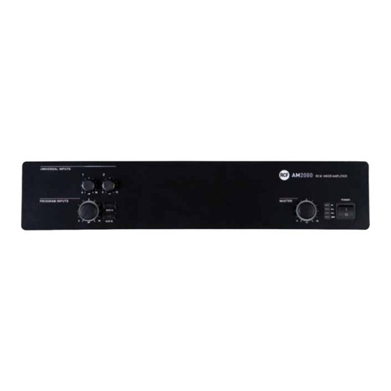
  • Page 30: Face Avant

    RCF S.p.A. vous remercie d’avoir choisi ce produit conçu pour garantir une fiabilité et des performances irréprochables. DESCRIPTION L’AM2160 est un mixeur/amplificateur de 80 watts avec 2 entrées audio micro/ligne sur connecteurs amovibles (la première d’entre elles est aussi disponible sur XLR) et 2 entrées auxiliaires pour les sources musicales (lecteurs CD, tuners, etc.).
  • Page 31 Bouton AUX A (avec LED) Active (LED allumée) l’entrée auxiliaire AUX INPUT A (son signal est envoyé à l’amplificateur interne et à la sortie PRE OUT). Lorsque cette fonction est active, le signal de l’entrée AUX INPUT B est « muté » (rendu muet) et la LED du bouton AUX B est éteinte.
  • Page 32: Panneau Arrière

    PANNEAU ARRIÈRE Entrée audio symétrique du canal 1 (connecteur amovible) : Point chaud de l’entrée audio Point froid de l’entrée audio Masse Commande  : entrée activée  / accès prioritaire quand connecté à la masse IMPORTANT : il faut relier la broche CMD à la masse du connecteur amovible correspondant ou utiliser la fonction VOX pour ouvrir l’entrée audio 1 (même lorsque le signal audio est relié...
  • Page 33 Exemples de réglages des sélecteurs DIP : DIP 1/3 DIP 2/4 MODE UTILISATION (EXEMPLES) – 20 dBu LIGNE Source audio ayant un niveau de sortie de -20 dB MICRO Microphones dynamiques LIGNE avec PHANTOM – 20 dBu ALIMENTATION Microphone d’annonce BM3001 FANTÔME MICRO avec PHANTOM ALIMENTATION...
  • Page 34 Réglages d’aigu (TREBLE) et de grave (BASS) des entrées AUX INPUT A et B. Entrée auxiliaire AUX INPUT A avec deux connecteurs RCA. Les deux canaux de la source stéréo connectés à l’entrée AUX INPUT A sont sommés en interne pour créer un signal mono ; il en va de même pour la source connectée à l’entrée AUX INPUT B. Réglage de GAIN de l’entrée AUX INPUT A.
  • Page 35: Fonctionnement

    (dont le niveau de priorité est inférieur) sont momentanément « mutées » (rendues muettes) jusqu’à suppression de l’ordre prioritaire. MICROPHONE D’ANNONCE RCF BM3001 (NON FOURNI) Le canal 2 possède une entrée sur port RJ 45 à laquelle on peut connecter un microphone d’annonce BM3001 (dans ce cas, il faut placer les sélecteurs DIP 1 et 2 en mode « LIGNE avec ALIMENTATION FANTÔME » ;...
  • Page 36: Connexion Des Enceintes

    CONNEXION DES ENCEINTES Utilisez une seule sortie – NE MÉLANGEZ PAS LES CONNEXIONS 100 / 70 V et 4 Ω ! SORTIES 70 / 100 V À VOLTAGE CONSTANT • Chaque enceinte doit posséder un transformateur ligne avec un voltage d’entrée égal au voltage de la ligne (100 ou 70 V).
  • Page 37: Modifier Le Voltage De L'alimentation

    MODIFIER LE VOLTAGE DE L’ALIMENTATION IMPORTANT : cette section du manuel s’adresse exclusivement à du personnel qualifié. Les instructions suivantes doivent être ignorées par l’utilisateur du produit. Assurez-vous que l’appareil n’est pas branché au secteur (débranchez le cordon secteur). Retirez le capot de l’appareil.. Trouvez le connecteur 115/230 V permettant de modifier le voltage (sur l’image, il est encadré...
  • Page 38 SPÉCIFICATIONS AMPLIFICATEUR Puissance de sortie (RMS) 80 W Réponse en fréquence 50 Hz ÷ 16 kHz RAPPORT SIGNAL/BRUIT - Canaux 1 et 2 60 dB - Entrées auxiliaires 80 dB Distorsion (à 1 kHz, puissance nominale) < 0.3 % ÉGALISEUR DES ENTRÉES AUX INPUT - Bass –...
  • Page 39: Exemple De Connexions

    EXEMPLE DE CONNEXIONS RADIO/RÉCEPTEUR BM 3001 MICRO CD/DVD...
  • Page 40 RCF S.p.A. reserves the right to make odifications without prior notice. Sauf erreurs et omissions éventuelles. RCF S.p.A. se réserve le droit de modifier ce document sans notification préalable. the rules of sound RCF SpA: Via Raffaello, 13 - 42010 Reggio Emilia Italy >...

Table des Matières