Clarke Focus 28" Cylindrical iDrive Manuels
Manuels et Guides d'utilisation pour Clarke Focus 28" Cylindrical iDrive. Nous avons 2 Clarke Focus 28" Cylindrical iDrive manuels disponible en téléchargement PDF gratuit: Manuel D'utilisation

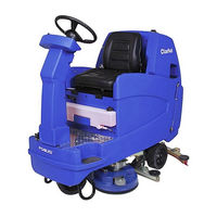
Clarke Focus 28" Cylindrical iDrive Manuel D'utilisation (138 pages)
Marque: Clarke
|
Catégorie: Machines à plancher
| Taille: 1 MB
Table des Matières
Clarke Focus 28" Cylindrical iDrive Manuel D'utilisation (128 pages)
Marque: Clarke
|
Catégorie: Machines à plancher
| Taille: 2 MB
Table des Matières
Produits Connexes
- Clarke FOCUS II MID-SIZE AUTOSCRUBBER
- Clarke Focus 28" Disc iDrive
- Clarke Focus 32" Boost Orbital iDrive
- Clarke FOCUS 32 Boost Orbita
- Clarke FOCUS II Micro Rider
- Clarke FOCUS II AUTOSCRUBBER Cylindrical 28
- Clarke FOCUS II RIDER AUTOSCRUBBER
- Clarke FOCUS II LARGE AUTOSCRUBBER
- Clarke Focus II Serie
- Clarke FOCUS2 Micro Rider