Metrix MX 56C Notice De Fonctionnement
Table des Matières
Les langues disponibles
Les langues disponibles
Liens rapides
Copyright ©
All manuals and user guides at all-guides.com
MX 56C
Notice de fonctionnement
User's manual
Bedienungsanleitung
Manual de instrucciones
FRANCAIS - page 1 -
ENGLISH -
DEUTSCH - Seite 38 -
ESPAÑOL - página 58 - Capítulo
MX 53C
MX 56C
Chapitre
page 19 -
Chapter
Kapitel
X01972A00 - Ed. 1 - 09/00
I
II
III
IV
Chapitres
Table des Matières

Manuels Connexes pour Metrix MX 56C


Sommaire des Matières pour Metrix MX 56C
- Page 1 All manuals and user guides at all-guides.com MX 56C Notice de fonctionnement User's manual Bedienungsanleitung Manual de instrucciones FRANCAIS - page 1 - Chapitre ENGLISH - page 19 - Chapter DEUTSCH - Seite 38 - Kapitel ESPAÑOL - página 58 - Capítulo...
- Page 2 All manuals and user guides at all-guides.com Multimètre digital portable...
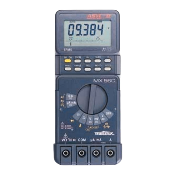
- Page 3 All manuals and user guides at all-guides.com Borne d'entrée calibres 11, 12, 13, 14, 15 Mesure de tensions 500 mV Entrée de référence du multimètre Mesure de tensions continues Borne d'entrée calibre µa mA Mesure de résistance Borne d'entrée calibre 10 A Mesure de capacité...
-
Page 4: Table Des Matières
All manuals and user guides at all-guides.com TABLE DES MATIERES 1. INSTRUCTIONS GENERALES ....................1 1.1. Consignes de sécurité......................1 1.2. Dispositifs de protection ....................... 2 1.3. Dispositifs de sécurité ......................3 1.4. Garantie ..........................3 1.5. Maintenance......................... 4 1.6. Déballage - Réemballage ..................... 4 2. -
Page 5: Instructions Generales
All manuals and user guides at all-guides.com Chapitre I INSTRUCTIONS GENERALES Vous venez d'acquérir un multimètre portable numérique 50.000 points ; nous vous remercions de votre confiance. Ce multimètre est conforme à la norme de sécurité CEI 1010, relative aux instruments de mesures électroniques. -
Page 6: Ouverture De L'appareil
All manuals and user guides at all-guides.com Chapitre I ∗ Lorsqu'on effectue des mesures de courant, ne jamais changer de calibre, ne pas brancher ou débrancher les cordons sans que le courant n'ait été coupé. De telles manoeuvres risqueraient de créer des surtensions de rupture pouvant fondre les fusibles, ou endommager l'instrument. -
Page 7: Dispositifs De Sécurité
All manuals and user guides at all-guides.com Chapitre I ∗ une résistance CTP (Coefficient de Température Positif) protège des surtensions permanentes inférieures ou égales à 600 V lors de mesures de type résistance, capacité et test diode. Cette protection se réarme automatiquement après la surcharge. -
Page 8: Maintenance
All manuals and user guides at all-guides.com Chapitre I 1.5. Maintenance Renseignements et coordonnées sur demande : Tél. 02.31.64.51.55 Fax 02.31.64.51.09 1.6. Déballage - Réemballage L’ensemble du matériel a été vérifié mécaniquement et électriquement avant l’expédition. Toutes les précautions ont été prises pour que l’instrument parvienne sans dommage à l’utilisateur. -
Page 9: Description De L'appareil
All manuals and user guides at all-guides.com Chapitre I DESCRIPTION DE L'APPAREIL Ce multimètre fait partie de la famille ASYC II (Advanced SafetY Concept 2ème génération) conçue pour donner à l'utilisateur une haute garantie de sécurité, une protection maximale et un niveau de performance inégalés. 2.1. -
Page 10: Mise En Service
All manuals and user guides at all-guides.com Chapitre I MISE EN SERVICE 3.1. Connexion des cordons Connecter le cordon noir dans la douille COM (ceci pour toutes les mesures à effectuer). Selon la position du commutateur rotatif, connecter le cordon rouge de la façon suivante : Position du commutateur rotatif Borne d'entrée Ω,... -
Page 11: Entretien Du Multimètre
All manuals and user guides at all-guides.com Chapitre I 3.5. Entretien du multimètre 3.5.1. Auto-vérification des fusibles Lorsque le fusible F1 (0,63 A) ou le fusible F2 (10 A) est hors service, l'afficheur indique "FUSE.1" ou "FUSE.2". Si les 2 fusibles sont hors service, l'afficheur indique "FUSES". Procéder au remplacement du ou des fusibles concernés. -
Page 12: Description Fonctionnelle
All manuals and user guides at all-guides.com Chapitre I DESCRIPTION FONCTIONNELLE 4.1. Touche SEL/ON Elle peut être utilisée pour remettre sous tension le multimètre après un arrêt automatique. Elle permet aussi d'accéder aux fonctions secondaires liées à chaque position du commutateur. - Page 13 All manuals and user guides at all-guides.com Chapitre I 4.1.3. Position V Mesure de tension DC SEL/ON Mesure de tension AC + DC SEL/ON Mesure de puissance résistive SEL/ON 4.1.4. Position Ω Ω Ω Ω Mesure de résistances SEL/ON Test continuité SEL/ON 4.1.5.
-
Page 14: Touche Range
All manuals and user guides at all-guides.com Chapitre I 4.1.6. Positions µA mA / 10A Mesure courant continu SEL/ON Mesure courant AC SEL/ON Mesure courant AC + DC SEL/ON 4.2. Touche RANGE Elle permet : • En mode AUTO, de passer en MANUEL (appui court) •... -
Page 15: Touche Zoom
All manuals and user guides at all-guides.com Chapitre I Mémorisation automatique Mettre les pointes de touches sur le point à mesurer. Un signal sonore indiquera si la mesure est stable. Lorsque l'on lèvera les pointes de touches, un second signal sonore indiquera l'affichage mémorisé... -
Page 16: Specifications Techniques
All manuals and user guides at all-guides.com Chapitre I SPECIFICATIONS TECHNIQUES Seules les valeurs affectées de tolérances ou les limites constituent des valeurs garanties. Les valeurs sans tolérances sont données à titre indicatif (norme NFC 42670). {Précision : ‘’n%L + nUR’’ signifie ‘’n% de la lecture + n Unité de Représentation’’ selon CEI 485}. -
Page 17: Courants Continus
All manuals and user guides at all-guides.com Chapitre I Courbe donnant l'erreur typique de mesure (calibres 5 V, 50 V, 500 V) Vin = 100 % F.S. 50000 pts Vin = 50 % F.S. 25000 pts Vin = 15 % F.S. 7500 pts Vin = 5 % F.S. -
Page 18: Résistances / Mode Continuité
All manuals and user guides at all-guides.com Chapitre I Nombre de points : 50 000 (ou 5000 voir paragraphe 3.4.) Sélection des gammes : automatique ou manuelle pour les gammes 500 µA, 5 mA, 50 mA, 500 mA Erreur additionnelle en fonction du facteur crête : 0.2 % pour un facteur crête de 2 à 3 0.5 % pour un facteur crête de 3 à... -
Page 19: Mesure De Tension De Seuil Diodes
All manuals and user guides at all-guides.com Chapitre I 5.7. Mesure de tension de seuil diodes Tensions mesurables : 0 à 2 volts 1 mA ± 20 % Courant de mesure : Résolution : 1 mV Protection : 600 V réarmable automatiquement 5.8. -
Page 20: Rapport Cyclique
All manuals and user guides at all-guides.com Chapitre I 5.11. Rapport cyclique : % + , % - θ θ θ θ x 100 % - = x 100 % + = Résolution : 0,01 % Durée minimale pour θ ou T - θ : 2 µs Durée maximale pour T : 0.8 s Durée minimale pour T : 100 µs −... -
Page 21: Caracteristiques Generales
All manuals and user guides at all-guides.com Chapitre I CARACTERISTIQUES GENERALES Ajustage Ce multimètre est équipé d'une mémoire non volatile contenant les caractéristiques d'étalonnage de toutes les gammes de mesure. Ce dispositif permet un ré-étalonnage par liaison série sans ouvrir l'appareil. L'appareil est livré accompagné d'un certificat de vérification. -
Page 22: Accessoires
All manuals and user guides at all-guides.com Chapitre I 6.1. Accessoires 6.1.1. Livrés avec le multimètre 1 jeu de cordons - pointes de touche de sécurité AG0475 1 pile 9 V 6F22 1 fusible de rechange 6,3x32 - 10 A - 50 kA/600 V AT0084 1 fusible de rechange 5x20 mm - 0,63 A - 1,5 kA/500 V AT0518... - Page 23 All manuals and user guides at all-guides.com Chapter II USER'S MANUAL CONTENTS 1. GENERAL INSTRUCTIONS ....................... 20 1.1. Precautions and safety measures....................20 1.2. Protection devices ......................... 22 1.3. Safety devices ..........................22 1.4. Warranty ............................22 1.5. Maintenance ..........................23 1.6.
-
Page 24: General Instructions
All manuals and user guides at all-guides.com Chapter II GENERAL INSTRUCTIONS You have just acquired a portable digital multimeter and we thank you for your confidence. This instrument complies with the specification of IEC publication 1010-1, concerning safety requirements for electronic measuring apparatus. To get the best service from this instrument, read carefully this user's manual and respect the detailed safety precautions. - Page 25 All manuals and user guides at all-guides.com Chapter II ∗ When the scale of the value to be measured is unknown, check that the scale initially set on the multimeter is the highest possible or, wherever possible, choose the autoranging mode. ∗...
-
Page 26: Protection Devices
All manuals and user guides at all-guides.com Chapter II 1.2. Protection devices ASYC II series instruments are fitted with various protection devices : ∗ Varistor protection for limiting transients of over 1100 V at the VΩ terminal, particularly 6 kV pulse streams as defined in French standard NFC 41-102. ∗... -
Page 27: Maintenance
All manuals and user guides at all-guides.com Chapter II Adaptation to a specific application not provided for in the specifications of the equipment or the user manual. Damage after a drop, a shock or flooding. The contents of this manual must not be reproduced in any form whatsoever without the consent of the manufacturer. -
Page 28: Description
All manuals and user guides at all-guides.com Chapter II DESCRIPTION This multimeter is one of the ASYC II (Advanced SafetY Concept, second generation) range, designed for a high degree of user safety, maximum protection and unrivalled performance. 2.1. Selector switch It is a standalone, handheld professional measuring instrument, capable of measuring the following quantities (accessed by the nine-position rotary selector switch) : ∗... -
Page 29: Commissioning
All manuals and user guides at all-guides.com Chapter II COMMISSIONING 3.1. Connecting the test leads Connect the black lead to the COM socket (for all measurements). Depending on the position of the selector switch, connect the red lead as follows : Rotary selector switch position Input terminal Ω,... -
Page 30: Multimeter Maintenance
All manuals and user guides at all-guides.com Chapter II 3.5. Multimeter maintenance 3.5.1. Fuse self-test When fuse F1 (0.63 A) or F2 (10 A) is blown, the display shows “FUSE.1” or “FUSE.2”, accordingly. If both fuses are blown, the display shows “FUSES”. Replace the fuse or fuses concerned. -
Page 31: Functional Description
All manuals and user guides at all-guides.com Chapter II FUNCTIONAL DESCRIPTION 4.1. SEL/ON key This can be used to switch on the multimeter again after an automatic shutdown. It can also be used to access secondary functions associated with the selector switch positions. The flowcharts below define these various functions. - Page 32 All manuals and user guides at all-guides.com Chapter II 4.1.3. V position DC voltage measurement SEL/ON AC + DC voltage measurement SEL/ON Resistive power measurement SEL/ON 4.1.4. Ω Ω Ω Ω position Resistance measurement SEL/ON Continuity test SEL/ON 4.1.5. position Capacitance measurement SEL/ON Diode voltage measurement...
-
Page 33: Range Key
All manuals and user guides at all-guides.com Chapter II 4.1.6. µA mA / 10 A positions DC current measurement SEL/ON AC current measurement SEL/ON AC+DC current measurement SEL/ON 4.2. RANGE key • In AUTO mode to switch to MANUAL mode (short press) •... -
Page 34: Zoom Key
All manuals and user guides at all-guides.com Chapter II 4.6. ZOOM key You can press this key to expand the bargraph readout five times for positive measurements and eleven times for bipolar measurements, one centred around zero (centre zero mode). Adjusts ohm-value references in dB and resistive power measurements When the current measurement is dB or resistive power, you can display the resistance reference with the ZOOM key (long press). -
Page 35: Technical Specifications
All manuals and user guides at all-guides.com Chapter II TECHNICAL SPECIFICATIONS Only those values assigned tolerances or limits are guaranteed values. Values without tolerances are given for information only (French standard NF C 42-670). {Accuracy : ‘’n% R + nD’’ means ‘’n% of the reading + n digits’’ as per IEC 485} 5.1. -
Page 36: Dc Current
All manuals and user guides at all-guides.com Chapter II Curve showing typical measurement error (5 V, 50 V, 500 V ranges) Vin = 100 % F.S. 50000 pts Vin = 50 % F.S. 25000 pts Vin = 15 % F.S. 7500 pts Vin = 5 % F.S. -
Page 37: Resistance / Continuity
All manuals and user guides at all-guides.com Chapter II Additional error according to crest factor : 0.2 % for a crest of 2 to 3 0.5 % for a crest of 3 to 6 (Specification given full scale for a squarewave signal pulse 200 µs wide) Additional error in IAC+DC with a direct current at input : 1 % 5.5. -
Page 38: Diode Threshold Voltage Measurement
All manuals and user guides at all-guides.com Chapter II 5.7. Diode threshold voltage measurement Measurable voltages : 0 to 2 V Measurement current : 1 mA ± 20 % Resolution : 1 mV Protection : 600 V , can be reset automatically. 5.8. -
Page 39: Duty Cycle
All manuals and user guides at all-guides.com Chapter II 5.11. Duty cycle: %+, %- θ θ θ θ x 10 0 x 100 % + = % - = Resolution : 0.01% Minimum duration for θ or T - θ : 2 µs Maximum duration for T : 0.8 s Minimum duration for T : 100 µs −... -
Page 40: General Specifications
All manuals and user guides at all-guides.com Chapter II GENERAL SPECIFICATIONS Adjustment This multimeter incorporates a non-volatile memory containing the adjustment charac- teristics for all measurement ranges. This enables the instrument to be re-adjusted via a serial link without opening the instrument. It is supplied with a certificate of verification. Safety According to IEC 1010 Environment... -
Page 41: Accessories
All manuals and user guides at all-guides.com Chapter II 6.1. Accessories 6.1.1. Supplied with the multimeter One set of test leads with safety probes AG0475 One 6F22 9 V battery One spare 10 A fuse, 6.3 x 32 mm, rupture capacity 50 kA/600 V AT0084 One spare 0.63 A fuse, 5 x 20 mm, rupture capacity 1.5 kA/500 V... - Page 42 All manuals and user guides at all-guides.com Kapitel III BEDIENUNGSANLEITUNG INHALTSVERZEICHNIS ALLGEMEINE HINWEISE..................... 39 1.1. Sicherheitsregeln ......................39 1.2. Schutzvorrichtungen ....................... 40 1.3. Sicherheitseinrichtungen....................41 1.4. Garantie.......................... 41 1.5. Wartung, Reparaturen ....................42 1.6. Auspacken/Verpacken des Gerätes ................42 GERÄTEBESCHREIBUNG ....................43 2.1.
-
Page 43: Allgemeine Hinweise
All manuals and user guides at all-guides.com Kapitel III ALLGEMEINE HINWEISE Sie haben soeben ein tragbares, numerisches 50.000 Punkte Vielfachmeßgerät erworben ; wir danken Ihnen für Ihr Vertrauen. Dieses Multimeter entspricht der Sicherheitsnorm CEI 1010 für elektronische Meßinstrumente. Für Ihre eigene Sicherheit sowie die des Geräts müssen Sie die in dieser Betriebsanleitung beschrie- benen Anweisungen befolgen. -
Page 44: Öffnen Des Gerätes
All manuals and user guides at all-guides.com Kapitel III ∗ Schalten Sie stets den Strom im Meßkreis ab, bevor Sie bei Strommessungen die Meßkabel an- oder abklemmen und bevor Sie den Meßbereich umschalten. Derartige Unterbrechungen Stromkreises können Überspannungen hervorrufen, die zum Schmelzen der Sicherungen führen oder das Instrument beschädigen. -
Page 45: Sicherheitseinrichtungen
All manuals and user guides at all-guides.com Kapitel III ∗ In den Meßarten "Widerstand", "Kapazität" und "Dioden-Schwellenspannung" schützt ein PTC-Widerstand (d.h. mit positivem Temperaturkoeffizienten) das Gerät vor ständigen Überspannungen bis zu 600 V. Nach Wegfall der Überlastung wird diese Schutzvorrichtung automatisch wieder zurückgesetzt. ∗... -
Page 46: Wartung, Reparaturen
All manuals and user guides at all-guides.com Kapitel III 1.5. Wartung, Reparaturen Wenden Sie sich für alle Überprüfungen und Eichungen Ihres Gerätes an die Nieder- lassung Ihres Landes. 1.6. Auspacken/Verpacken des Gerätes Vor dem Versand wurden die mechanischen und elektrischen Eigenschaften des Geräts eingehend geprüft und es wurden alle Vorkehrungen getroffen, damit das Gerät unbeschädigt beim Benutzer eintrifft. -
Page 47: Gerätebeschreibung
All manuals and user guides at all-guides.com Kapitel III GERÄTEBESCHREIBUNG Dieses Multimeter gehört zur Familie der ASYC II-Geräte (Advanced SafetY Concept der 2. Generation), die dem Benutzer größtmögliche Sicherheit, optimalen Schutz vor Fehl- bedienungen und ein bisher unerreichtes Leistungsspektrum bieten. 2.1. -
Page 48: Inbetriebnahme
All manuals and user guides at all-guides.com Kapitel III INBETRIEBNAHME 3.1. Anschluß der Meßkabel Schließen Sie das schwarze Meßkabel an die COM-Eingangsbuchse an (dies gilt für alle Messungen !). Je nach Meßart und Stellung des Drehschalters stecken Sie das rote Meßkabel in die untengenannte Eingangsbuchse: Stellung des Drehschalters Eingangsbuchse... -
Page 49: Wartung Des Multimeters
All manuals and user guides at all-guides.com Kapitel III 3.5. Wartung des Multimeters 3.5.1. Selbsttest der Sicherungen Falls die Sicherungen F1 (0,63 A) oder F2 (10 A) durchgebrannt sind, erscheinen die Meldungen "FUSE.1" bzw. "FUSE.2" in der Anzeige. Sind beide Sicherungen defekt, erscheint die Meldung "FUSES". Ersetzen Sie die durchgebrannte(n) Sicherung(en). -
Page 50: Funktionsbeschreibung
All manuals and user guides at all-guides.com Kapitel III FUNKTIONSBESCHREIBUNG 4.1. Taste SEL/ON Mit dieser Taste können Sie das Multimeter nach Ansprechen der Abschalteautomatik wiedereinschalten. Weiterhin können Sie mit dieser Taste auf die zu den verschiedenen Schalterstellungen gehörenden Zweitfunktionen zugreifen. Die folgenden Diagramme verdeutlichen die anwählbaren Zweitfunktionen: 4.1.1. - Page 51 All manuals and user guides at all-guides.com Kapitel III 4.1.3. Stellung V DC Spannungsmessung SEL/ON AC+DC Spannungsmessung SEL/ON Ohm'sche Leistung SEL/ON 4.1.4. Stellung Ω Ω Ω Ω Widerstandsmessung SEL/ON Durchgangsprüfung SEL/ON 4.1.5. Stellung Kapazitätsmessung SEL/ON Messung der Schwellenspannung SEL/ON Tragbares Digital-Multimeter...
-
Page 52: Taste Range
All manuals and user guides at all-guides.com Kapitel III 4.1.6. Stellung µA mA / 10A DC-Strommessung SEL/ON AC-Strommessung SEL/ON AC+DC-Strommessung SEL/ON 4.2. Taste RANGE Mit dieser Taste können Sie : • Von automatischer Bereichswahl auf manuelle Bereichswahl umschalten (Taste kurz drücken). -
Page 53: Taste Hold
All manuals and user guides at all-guides.com Kapitel III 4.5. Taste HOLD Kurz drücken : Fixiert den aktuellen Meßwert in der Anzeige. Lang drücken : Schaltet in den Meßarten V , mV, V die automatische Speicherung ein bzw. aus. Automatische Speicherung Bringen Sie die Meßspitzen in Kontakt mit der Meßstelle. -
Page 54: Taste Hz
All manuals and user guides at all-guides.com Kapitel III 4.8. Taste Hz In den Meßarten V , mV, mA und 10 A wird durch wiederholtes Drücken der Taste Hz zwischen den folgenden Meßfunktionen umgeschaltet : - Frequenzmessung (Hz) - Messung des positiven Tastverhältnisses (% +) (Einschaltdauer) - Messung des negativen Tastverhältnisses (% - ) (Ausschaltdauer) - Zählung von positiven Impulsen ( - Zählung von negativen Impulsen (... -
Page 55: Technische Daten
All manuals and user guides at all-guides.com Kapitel III TECHNISCHE DATEN Nur die mit Toleranzen oder mit Grenzwerten angegebenen Daten sind zugesicherte Eigenschaften des Gerätes. Werte ohne Toleranzangaben dienen lediglich zur Information (franz. Norm NFC 42670). {Abweichung : ‘’n % L + n D’’ bedeutet ‘’n % von der Ablesung + n Digits’’ nach IEC 485} 5.1. -
Page 56: Gleichströme
All manuals and user guides at all-guides.com Kapitel III Kurve mit dem typischen Meßfehler in Abhängigkeit von der Frequenz (Meßbereiche 5 V, 50 V, 500 V) Vin = 100 % F.S. 50000 pts Vin = 50 % F.S. 25000 pts Vin = 15 % F.S. -
Page 57: Widerstände, Durchgangsprüfung
All manuals and user guides at all-guides.com Kapitel III Anzahl Meßpunkte : 50 000 (oder 5 000 - siehe Abschnitt 3.4.) Bereichsumschaltung : automatisch oder manuell zwischen den Bereichen 500 µA, 5 mA, 50 mA, 500 mA. Zusätzlicher Fehler durch den Scheitelfaktor des Signals : 0,2 % für Scheitelfaktoren zwischen 2 bis 3 0,5 % für Scheitelfaktoren zwischen 3 bis 6 (Fehlerangabe für Rechtecksignal am Bereichsende mit 200 µs Impulsbreite) -
Page 58: Dioden-Schwellenspannung
All manuals and user guides at all-guides.com Kapitel III 5.7. Dioden-Schwellenspannung Meßbereich : 0 bis 2 V 1 mA ± 20 % Meßstrom : Auflösung : 1 mV Überlastschutz : 600 V mit automatischer Rücksetzung 5.8. dB-Messung Anzeige des Meßwertes in "dBm" in Bezug auf einen frei einstellbaren Lastwiderstand zwischen 1 Ω... -
Page 59: Tastverhältnis
All manuals and user guides at all-guides.com Kapitel III 5.11. Tastverhältnis : % + , % - θ θ θ θ x 100 x 100 % + = % - = Auflösung : 0,01 % Mindest-Impulsbreite θ oder T - θ : 2 µs Maximale Impulsbreite für T : 0.8 s... -
Page 60: Allgemeine Technische Daten
All manuals and user guides at all-guides.com Kapitel III ALLGEMEINE TECHNISCHE DATEN Kalibrierung Das Multimeter besitzt einen nicht-flüchtigen Speicher in dem sämtlichen Kalibrierdaten aller Meßbereiche abgelegt werden. Dadurch ist eine Nachkalibrierung des Gerätes über seriellen Datenaustausch ohne Öffnen des Gerätes möglich. Bei Auslieferung liegt dem Instrument ein Prüfung-Zertifikat bei. -
Page 61: Zubehör
All manuals and user guides at all-guides.com Kapitel III 6.1. Zubehör 6.1.1. Serienmäßiger Lieferumfang 1 Satz Meßkabel mit Sicherheits-Tastspitzen AG0475 1 9 V-Blockbatterie (6F22) 1 Ersatzsicherung 6,3x32 - 10 A - 50 kA/600 V AT0084 1 Ersatzsicherung 5x20 - 0,63 A - 1,5 kA/500 V AT0518 1 Bedienungsanleitung 6.1.2. - Page 62 All manuals and user guides at all-guides.com Capítulo IV MANUAL DE INSTRUCCIONES INDICE 1. INSTRUCCIONES GENERALES......................59 1.1 Instrucciones de seguridad ......................59 1.2 Dispositivos de protección ......................60 1.3 Dispositivos de seguridad ......................61 1.4 Garantía............................61 1.5 Mantenimiento..........................61 1.6 Desembalaje - embalaje ........................
-
Page 63: Instrucciones Generales
All manuals and user guides at all-guides.com Capítulo IV INSTRUCCIONES GENERALES Acaba usted de adquirir un multímetro portátil digital de 50.000 puntos. Le agradecemos su confianza en nosotros. Este multímetro está de acuerdo a la norma de seguridad CEI 1010, relativa a los instrumentos de medidas electrónicas. -
Page 64: Dispositivos De Protección
All manuals and user guides at all-guides.com Capítulo IV ∗ Cuando realice medidas de corriente, no conecte o desconecte los cables sin aislar antes la corriente. Si no toma esta precaución, podrían generarse impulsos de corriente lo bastante elevados para quemar los fusibles o dañar el instrumento. ∗... -
Page 65: Dispositivos De Seguridad
All manuals and user guides at all-guides.com Capítulo IV 1.3 Dispositivos de seguridad ∗ El sistema patentado SECUR'X bloquea los cables una vez insertados en el instrumento para que no puedan desconectarse accidentalmente. Con este sistema, muy fácil de usar, las clavijas tipo banana se insertan sin esfuerzo y quedan inmovilizadas en su posición mediante una lengüeta que encaja en la ranura de la clavija. -
Page 66: Desembalaje - Embalaje
All manuals and user guides at all-guides.com Capítulo IV 1.6 Desembalaje - embalaje Todos los componentes mecánicos y eléctricos de este equipo han sido comprobados antes de su expedición y se han tomado todas las precauciones necesarias para garantizar la llegada del instrumento a su destino en perfectas condiciones. -
Page 67: Descripcion
All manuals and user guides at all-guides.com Capítulo IV DESCRIPCION Este multímetro es un instrumento de la familia ASYC II (Advanced SafetY Concept, segunda generación), diseñado para proporcionar un alto grado de seguridad al usuario, máxima protección y un rendimiento inigualable. 2.1 Mando selector Este multímetro es un instrumento de medida profesional, de mano y autónomo, capaz de medir las siguientes magnitudes (a las que se accede con ayuda del mando selector giratorio de nueve... -
Page 68: Primer Encendido
All manuals and user guides at all-guides.com Capítulo IV PRIMER ENCENDIDO 3.1 Conexión de los cables de medida Conecte el cable negro al terminal COM (común para todas las medidas). El cable rojo deberá conectarlo a uno de los terminales siguientes según la posición del selector. Posición del selector giratorio Terminal de entrada Ω,... -
Page 69: Mantenimiento Del Multímetro
All manuals and user guides at all-guides.com Capítulo IV 3.5 Mantenimiento del multímetro 3.5.1 Autocomprobación de fusibles Cuando está quemado el fusible F1 (0.63 A) o el fusible F2 (10 A), aparece en pantalla la indicación "FUSE.1" o "FUSE.2" según corresponda. Si están quemados los dos fusibles, la pantalla indica "FUSES". -
Page 70: Descripcion Funcional
All manuals and user guides at all-guides.com Capítulo IV DESCRIPCION FUNCIONAL 4.1 Tecla SEL/ON Esta tecla permite reencender el multímetro después de un apagado automático. También sirve para acceder a funciones secundarias relacionadas con las posiciones del selector. Los siguientes diagramas de flujo definen esas funciones. 4.1.1 Posición V Medidas de tensión alterna SEL/ON... - Page 71 All manuals and user guides at all-guides.com Capítulo IV 4.1.3 Posición V Medidas de tensión continua SEL/ON Medidas de tensión alterna + continua SEL/ON Medidas de potencia resistiva SEL/ON 4.1.4 Posición Ω Ω Ω Ω 4.1.4 4.1.4 4.1.4 Medidas de resistencia SEL/ON Prueba de continuidad SEL/ON...
-
Page 72: Tecla Range
All manuals and user guides at all-guides.com Capítulo IV 4.1.6 Posiciones µA mA / 10 A Medidas de corriente continua SEL/ON Medidas de corriente RMS SEL/ON Medidas de corriente TRMS SEL/ON 4.2 Tecla RANGE Esta tecla se utiliza : • En modo AUTO, para conmutar a modo MANUAL (presión breve). •... -
Page 73: Tecla Zoom
All manuals and user guides at all-guides.com Capítulo IV 4.6 Tecla ZOOM Pulsando esta tecla se amplía la lectura del gráfico de barras, cinco veces si se trata de medidas positivas y once si las medidas son bipolares, con una centrada en torno al cero (modo de centrado en cero). -
Page 74: Especificaciones Tecnicas
All manuals and user guides at all-guides.com Capítulo IV ESPECIFICACIONES TECNICAS Sólo se garantizan los valores que tienen asignados límites o tolerancias. Los valores sin tolerancias se facilitan únicamente a título informativo (norma francesa NF C 42-670). {Precisión : ‘’n%L + nD’’ significa ‘’n% de la lectura + n digitos’’ según IEC 485}. 5.1 Tensiones continuas (DC) Posición del Impedancia de... -
Page 75: Corriente Continua (Dc)
All manuals and user guides at all-guides.com Capítulo IV Curva que indica el error de medida típico (rangos de 5 V, 50 V, 500 V) Vin = 100 % F.S. 50000 pts Vin = 50 % F.S. 25000 pts Vin = 15 % F.S. 7500 pts Vin = 5 % F.S. -
Page 76: Resistencia/Continuidad
All manuals and user guides at all-guides.com Capítulo IV Número de puntos : 50 000 (o 5000 ver sección 3.4.) Selección de rango : automática o manual en los rangos de 500 µA, 5 mA, 50 mA, 500 mA Error adicional en función del factor de pico : 0,2 % para un factor de pico de 2 a 3 0,5 % para un factor de pico de 3 a 6 (especificación a fondo de escala para una señal pulsante de onda cuadrada de 200 µs... -
Page 77: Medida De La Tensión Umbral De Diodos
All manuals and user guides at all-guides.com Capítulo IV 5.7 Medida de la tensión umbral de diodos Tensiones medibles : 0 a 2 V Corriente en la medición : 1 mA ± 20 % Resolución : 1 mV Protección : 600 V , con rearme automático 5.8 Función dB... -
Page 78: Factor De Servicio
All manuals and user guides at all-guides.com Capítulo IV 5.11 Factor de servicio: %+, %- θ θ θ θ x 10 0 x 100 % + = % - = Resolución : 0.01% Duración mínima para θ o T - θ : 2 µs Duración máxima para T : 0.8 s Duración mínima para T : 100 µs −... -
Page 79: Especificaciones Generales
All manuals and user guides at all-guides.com Capítulo IV 6. ESPECIFICACIONES GENERALES Calibración Este multímetro tiene una memoria no volátil que almacena las características de calibración para todos los rangos de medida, lo que permite recalibrar el instrumento a través de un enlace serie sin necesidad de abrirlo. -
Page 80: Accesorios
All manuals and user guides at all-guides.com Capítulo IV 6.1 Accesorios 6.1.1 Suministrados con el multímetro Un juego de cables de medida con sondas de seguridad AG0475 Una pila de 9 V 6F22 Un fusible de reserva de 10 A, 6,3 x 32 mm, capacidad de desconexión 50 kA/600 V AT0084 Un fusible de reserva de 0,63 A, 5 x 20 mm,... - Page 81 All manuals and user guides at all-guides.com Fig. 2 Soulever la béquille située à Fig. 3 L'enlever en la tournant. l'arrière. Fig. 2 Lift the stand on the back. Fig. 3 Remove it by rotating. Abbg. 2 Die Klappstütze auf der Abbg.