
Manuels Connexes pour Intermatic Grasslin thermio essential H Brf

Sommaire des Matières pour Intermatic Grasslin thermio essential H Brf
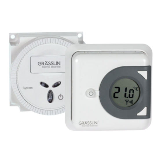
- Page 1 Bedienungsanleitung Manuale operativo Operating manual Instrucciones de manejo Mode d'emploi thermio™ essential H Brf...
- Page 2 Diese Anleitung ermöglicht den sicheren und effizienten Umgang mit dem Raumthermostat "thermio essential H rf" (im Folgenden "Gerät"). Diese Anleitung ist Bestandteil des Geräts und muss für jeden, der mit dem Gerät umgeht, jederzeit zugänglich aufbewahrt werden. Diese Anleitung ermöglicht den sicheren und effizienten Umgang mit dem "Aktor RecFM/2" (im Fol- genden "Gerät").
- Page 3 Die Überlassung dieser Anleitung an Dritte, Vervielfältigungen in jeglicher Art und Form – auch auszugs- weise – sowie die Verwertung und/oder Mitteilung des Inhaltes sind ohne schriftliche Genehmigung der Grässlin GmbH (im Folgenden "Hersteller") außer für interne Zwecke nicht gestattet. Zuwiderhand- lungen verpflichten zu Schadenersatz.
-
Page 5: Table Des Matières
Übersicht....................7 Aufbau und Funktion......................7 Raumthermostat (Sender)....................8 Aktor (Empfänger)......................10 Sicherheit..................... 11 Installation.................... 14 Aufstellort wählen....................... 14 Raumthermostat (Sender)....................15 Montage auf eine Unterputzdose................... 15 Aufputzmontage......................18 Hysterese einstellen...................... 20 Aktor (Empfänger)....................... 21 Montage an den Boiler....................21 Funkverbindung................... - Page 6 Funkverbindung vorbereiten....................26 Funkverbindung herstellen....................29 Bedienung.................... 31 Raumthermostat (Sender)....................31 Soll-Temperatur einstellen.................... 31 Raumthermostat in den Stand-by-Betrieb versetzen............32 Aktor (Empfänger) manuell bedienen.................. 33 Systemzustand..................34 LED-Anzeige........................34 Entsorgung................... 35...
-
Page 7: Übersicht
Übersicht Aufbau und Funktion Funktionsbeschreibung Die Funktionaltität besteht nur, wenn das Raumthermostat (Sender) mit dem Aktor (Empfänger) ver- bunden ist. Das Raumthermostat und der Aktor werden ausschließlich in geschlossenen Räumen mon- tiert und regeln einen Temperaturbereich von +5 °C bis +35 °C. Wenn das Raumthermostat über den Temperaturfühler einen Temperaturabfall erkennt, wird das Heiz- system eingeschaltet und nach Erreichen der Soll-Temperatur wieder ausgeschaltet. -
Page 8: Raumthermostat (Sender)
RAUMTHERMOSTAT (SENDER) Abb. 1: Übersicht Raumthermostat... - Page 9 Kipptaster Schaltdifferenz-Symbol Heizen-Symbol Taste oben Anzeige für Soll- und Ist-Temperatur Funkverbindung Taste unten Batterie-Symbol Kabeldurchführung Reset-Taste Funkverbindungstaste...
-
Page 10: Aktor (Empfänger)
AKTOR (EMPFÄNGER) Abb. 2: Übersicht Aktor (Empfänger) "RecFM/2" LED EIN/AUS-System (blau) DIP-Switch Reset-Taste Abdeckung für DIP-Switch LED Funkverbindung (rot) Manueller Handschalter (EIN/AUS) Elektrischer Anschluss... -
Page 11: Sicherheit
Sicherheit Bestimmungsgemäße Verwendung • Das Raumthermostat (Sender) dient ausschließlich der Regelung der Raumtemperatur und funktio- niert nur in Kombination mit dem Aktor (Empfänger). • Das Raumthermostat (Sender) und der Aktor (Empfänger) werden ausschließlich in geschlossenen Räumen montiert und regeln die Raumtemperatur in einem Temperaturbereich von +5 °C bis +35 °C. - Page 12 Restrisiken Lebensgefahr durch elektrischen Schlag! Unsachgemäße Montage und Installation des Geräts können zu lebensgefähr- lichen elektrischen Spannungen führen. WARNUNG! − Montage und Anschluss ausschließlich durch Elektrofachkraft durch- führen lassen.
- Page 13 Verletzungsgefahr bei falschem Umgang mit Batterien! Bei falschem Umgang mit Batterien besteht die Gefahr, dass die Batterien explodieren oder dass gesundheitsschädliche Flüssigkeit aus den Batterien WARNUNG! austritt. − Niemals Batterien beschädigen oder deformieren. − Niemals die Kontakte (Plus- und Minuspol) der Batterien kurzschließen. −...
-
Page 14: Installation
Installation Aufstellort wählen Aufstellort Um eine fehlerfreie Messung des Raumthermostats zu gewährleisten, den Aufstellort richtig wählen. Abb. 3: Anforderungen an den Aufstellort... -
Page 15: Raumthermostat (Sender)
Raumthermostat (Sender) MONTAGE AUF EINE UNTERPUTZDOSE Personal: • Elektrofachkraft Montageplatte montieren Die Montageplatte mit Schrauben (3,5 x 25 mm) auf die Unterputzdose montieren (Abb. 5). Der Pfeil (Abb. 5/1) auf der Montageplatte muss nach oben zeigen. Gehäusedeckel demontieren Die Schraube am Gerätegehäuse mit dem Kreuzschlitzschraubendreher lösen und Gehäusedeckel demontieren. - Page 16 Batterie einlegen Abb. 4: Batterie einlegen Die 2 Alkalibatterien vom Typ 1,5 V AA LR6 mit richtiger Polung (Abb. 4) in den Gehäusedeckel einlegen.
- Page 17 Gehäuseboden montieren Abb. 5: Montage auf eine Unterputzdose und Aufputzmontage Montage auf eine Unterputzdose ohne Dübel mit Montageplatte Aufputzmontage ohne Montageplatte mit Dübel Den Gehäuseboden des Geräts mit den Schrauben (3 x 6 mm) auf die Montageplatte montieren (Abb. 5).
-
Page 18: Aufputzmontage
Gehäuse schließen Den Gehäusedeckel auf den Gehäuseboden setzen und die Schraube am Gerätegehäuse mit dem Kreuzschlitzschraubendreher festschrauben. AUFPUTZMONTAGE Personal: • Elektrofachkraft Gehäusedeckel demontieren Die Schraube am Gerätegehäuse mit dem Kreuzschlitzschraubendreher lösen und den Gehäusede- ckel demontieren. Das Lochbild vom Gehäuseboden an die Wand übertragen und an den markierten Positionen Löcher bohren (5-mm-Durchmesser und mindestens 25 mm tief). - Page 19 Batterie einlegen Die 2 Alkalibatterien vom Typ 1,5 V AA LR6 mit richtiger Polung (Abb. 4) in den Gehäusedeckel einlegen. Gehäuse schließen Den Gehäusedeckel auf den Gehäuseboden setzen und die Schraube am Gerätegehäuse mit dem Kreuzschlitzschraubendreher festschrauben. Die Montage des Geräts ist abgeschlossen. ð...
-
Page 20: Hysterese Einstellen
HYSTERESE EINSTELLEN Auswahl der Hysterese Beispiel Die Hysterese kann zwischen ± 0,2 K, 0,4 K, 0,6 K, 0,8 K und 1 K (Werkseinstellung 0,4 K) (K = Kelvin) eingestellt werden. Wenn die Hysterese z. B. 1 K beträgt und das Raumthermostat auf eine Soll-Temperatur von 20 °C regeln soll, wird das Raumthermostat bei 19 °C eingeschaltet und bei 20 °C wieder ausgeschaltet. -
Page 21: Aktor (Empfänger)
Wenn die Hysterese eingestellt ist, 5 Sekunden warten, bis das Schaltdifferenz-Symbol aufhört zu blinken. Das Raumthermostat regelt nun erst, sobald die Soll-Temperatur um die soeben eingestellte ð Hysterese unterschritten wird. Aktor (Empfänger) MONTAGE AN DEN BOILER Personal: • Elektrofachkraft Am Boiler kann eine Blindplatte oder beispielsweise eine mechanische Zeit- schaltuhr (Abb. - Page 22 Abb. 6: z.B. mechanische Zeitschaltuhr...
- Page 23 Aktor (Empfänger) montieren Abb. 7: Aktor (Empfänger) montieren Den Aktor (Empfänger) (Abb. 7/1) in die Montageplatte am Boiler einsetzen. Die 4 Schrauben am Aktor (Empfänger) festdrehen (Abb. 7).
- Page 24 Anschließen Abb. 8: Anschlussplan Aktor (Empfänger) Neutralleiter Phase COM (Wechselkontakt, gemeinsamer Leiter Kontakt) NC (Ruhekontakt, Öffner Kontakt) NO (Arbeitskontakt, Schließer Kontakt) Die Anschlusslaschen (Flach DIN 6,3) anhand des Anschlussplans (Abb. 8) in den entsprechenden Kabelschuh einführen.
- Page 25 Aktor (Empfänger) einbauen Abb. 9: Aktor (Empfänger) einbauen Den montierten Aktor (Empfänger) (Abb. 9/1) in den Boiler einbauen.
-
Page 26: Funkverbindung
Funkverbindung Funkverbindung vorbereiten Abb. 10: Raumcode-Tabelle... - Page 27 Das Raumthermostat (Sender) und der jeweilige Aktor (Empfänger) sind über ein Funksignal verbunden. Damit sich Raumthermostat und Aktor finden, muss an beiden Geräten der gleiche Code (Raumcode) eingestellt sein. Am DIP-Switch des Aktors (Empfängers) kann kein Hauscode eingestellt werden, deshalb muss der Hauscode am Raumthermostat auf Werkseinstellung 00 eingestellt sein, um eine Verbindung herzu- stellen.
- Page 28 Abb. 11: Raumcode einstellen Die Verbindung zwischen Raumthermostat und Aktor kann nur aufgebaut werden, wenn der Raumcode (Abb. 11/1) am Raumthermostat mit der DIP-Switch-Position im Empfänger übereinstimmt.
-
Page 29: Funkverbindung Herstellen
Funkverbindung herstellen Personal: • Benutzer Raumcode einstellen am Raumthermostat (Sender) Die Funkverbindungstaste (Abb. 1/11) auf dem Gerät drücken. Auf der Anzeige blinkt "00 H" (Abb. 1/5). ð Der Hauscode muss unverändert bleiben, sonst kann keine Ver- bindung zum Aktor (Empfänger) hergestellt werden. Die Taste oben (Abb. - Page 30 Der am Raumthermostat einstellbare Raumcode liegt in einem Bereich von 00 – 16 und muss mit der DIP-Switch-Einstellung am Aktor übereinstimmen. Die Taste oben (Abb. 1/4) drücken, um den Wert zu erhöhen, oder die Taste unten (Abb. 1/7), um den Wert zu verringern. Die Funkverbindungstaste (Abb.
-
Page 31: Bedienung
Bedienung Raumthermostat (Sender) SOLL-TEMPERATUR EINSTELLEN Personal: • Benutzer Den Kipptaster (Abb. 1/1) nach oben oder nach unten drücken, um das Heizsystem anzusteuern. ð Der Kipptaster fällt auf die Ausgangsstellung zurück. Zum Einstellen der Soll-Temperatur die Taste oben (Abb. 1/4) oder die Taste unten (Abb. 1/7) 2 Mal kurz nacheinander drücken. -
Page 32: Raumthermostat In Den Stand-By-Betrieb Versetzen
Wenn die Soll-Temperatur eingestellt ist, 5 Sekunden warten, bis der Sollwert aufhört zu blinken. ð Das Gerät steuert das Heizsystem an und die Raumtemperatur wird auf die eingestellte Soll- Temperatur geregelt. Das Einstellen der Soll-Temperatur auf einen höheren Wert beschleunigt nicht das Aufheizen des Raums. Die Aufheizge- schwindigkeit wird ausschließlich durch die Bedingungen im Heizsystem bestimmt. -
Page 33: Aktor (Empfänger) Manuell Bedienen
Frostschutzfunktion Das Gerät hält die Raumtemperatur auf + 5 °C. Das Heizsystem wird automatisch eingeschaltet, wenn die Raumtemperatur unter + 5 °C sinkt. Aktor (Empfänger) manuell bedienen Personal: • Benutzer Bei Störungen oder schlechter Funkverbindung kann über den manu- ellen Handschalter (Abb. 2/6) jederzeit EIN/AUS geschaltet werden. Wenn nach 10 Minuten keine Funkverbindung aufgebaut wird, schaltet der Schaltkontakt aus. -
Page 34: Systemzustand
Systemzustand LED-Anzeige An den Farben der LEDs kann der Zustand des Aktors (Empfängers) abgelesen werden. Farben Zustand des Aktors (Empfänger) LED EIN/AUS-System (Abb. 2/1) leuchtet blau Verbraucher ist an. LED EIN/AUS-System (Abb. 2/1) leuchtet nicht Verbraucher ist aus. LED Funkverbindung (Abb. 2/5) blinkt rot Der Empfänger ist mit dem Sender ver- bunden. -
Page 35: Entsorgung
Entsorgung Unsachgemäße Entsorgung Gefahr für die Umwelt durch falsche Entsorgung! Durch falsche Entsorgung können Gefahren für die Umwelt entstehen. − Elektroschrott und Elektronikkomponenten fachgerecht entsorgen, d. h. UMWELTSCHUTZ! getrennt nach Materialgruppen der zu entsorgenden Teile. − Batterien/Akkumulatoren (Richtlinie 2006/66/EG) und Elektro- oder Elek- tronikschrott keinesfalls mit dem Restmüll entsorgen. - Page 37 This manual ensures safe and efficient use of the “thermio essential H rf” room thermostat (referred to as “device” in the following). This manual is a component of the device and must remain accessible at all times for everyone who uses the device. This manual ensures safe and efficient use of the “RecFM/2 actuator”...
- Page 38 Handover of this manual to third parties, reproductions of any type and form – including excerpts – and use and/or disclosure of the content without the written permission of Grässlin GmbH (referred to as “manufacturer” in the following), except for internal purposes, is not permitted. Violations will result in liability for compensation.
- Page 39 Overview....................41 Design and function......................41 Room thermostat (transmitter)..................42 Actuator (receiver)......................44 Safety....................45 Installation.................... 47 Selecting an installation location..................47 Room thermostat (transmitter).................... 48 Installation in a flush-mounted socket................48 On-wall mounting......................51 Setting the hysteresis....................53 Actuator (receiver)......................54 Installation on the boiler....................
- Page 40 Preparing the radio communication..................59 Establishing radio communication..................62 Operation..................... 64 Room thermostat (transmitter).................... 64 Setting the temperature setpoint................... 64 Putting the room thermostat into stand-by mode............65 Manually operating the actuator (receiver)................66 System status..................67 LED display......................... 67 Disposal....................
-
Page 41: Overview
Overview Design and function Description of function The functions are only available if the room thermostat (transmitter) is connected to the actuator (receiver). The room thermostat and the actuator may only be installed indoors and are used for regu- lating the room temperature in a temperature range from +5°C to +35°C. If the room thermostat’s temperature sensor detects a drop in temperature, the heating system is switched on and it is then switched off again once the temperature setpoint is reached. -
Page 42: Room Thermostat (Transmitter)
ROOM THERMOSTAT (TRANSMITTER) Fig. 1: Overview of room thermostat... - Page 43 Toggle key Switching differential symbol Heating symbol Top button Display for setpoint and current temperature Radio communication Bottom button Battery symbol Cable feed-through Reset button Radio communication button...
-
Page 44: Actuator (Receiver)
ACTUATOR (RECEIVER) Fig. 2: Overview of actuator (receiver) “RecFM/2” System ON/OFF LED (blue) DIP switch Reset button Cover for DIP switch Radio communication LED (red) Manual switch (ON/OFF) Electrical connection... -
Page 45: Safety
Safety Intended use • The room thermostat (transmitter) is used exclusively for regulating the room temperature and can only function in combination with the actuator (receiver). • The room thermostat (transmitter) and the actuator (receiver) may only be installed indoors and are used for regulating the room temperature in a temperature range from +5°C to +35°C. - Page 46 Risk of injury if batteries are handled incorrectly! Incorrect handling of batteries can result in a risk of batteries exploding or harmful liquids escaping from the batteries. WARNING! − Never damage or deform batteries. − Never short-circuit the contacts (plus and minus poles) of the batteries. −...
-
Page 47: Installation
Installation Selecting an installation location Installation location In order to ensure fault-free measurement by the room thermostat, choose the right installation location. Fig. 3: Installation location requirements... -
Page 48: Room Thermostat (Transmitter)
Room thermostat (transmitter) INSTALLATION IN A FLUSH-MOUNTED SOCKET Personal: • Qualified electrician Installing the mounting plate Attach the mounting plate to the flush-mounted socket with screws (3.5 x 25 mm) (Fig. 5). The arrow (Fig. 5/1) on the mounting plate should point upwards. Removing the housing cover Undo the screw on the device housing with the Phillips screwdriver and remove the housing cover. - Page 49 Inserting the battery Fig. 4: Inserting the battery Insert the two alkaline batteries of type 1.5 V AA LR6 into the housing cover, ensuring the correct polarity (Fig. 4).
- Page 50 Installing the housing base Fig. 5: Installation in a flush-mounted socket and on-wall mounting Installation in a flush-mounted socket without wall-plugs and with mounting plate On-wall mounting without mounting plate and with wall-plugs Attach the housing base of the device to the mounting plate with the screws (3 x 6 mm) (Fig. 5).
-
Page 51: On-Wall Mounting
Closing the housing Place the housing cover on the housing base and tighten the screw on the device housing with the Phillips screwdriver. ON-WALL MOUNTING Personal: • Qualified electrician Removing the housing cover Undo the screw on the device housing with the Phillips screwdriver and remove the housing cover. Mark the hole pattern from the housing base onto the wall and drill holes at the points you marked (5 mm diameter and at least 25 mm deep). - Page 52 Inserting the battery Insert the two alkaline batteries of type 1.5 V AA LR6 into the housing cover, ensuring the correct polarity (Fig. 4). Closing the housing Place the housing cover on the housing base and tighten the screw on the device housing with the Phillips screwdriver.
-
Page 53: Setting The Hysteresis
SETTING THE HYSTERESIS Selecting the hysteresis Example The hysteresis can be set between ± 0.2 K, 0.4 K, 0.6 K, 0.8 K and 1 K (factory setting 0.4 K) (K = Kelvin). If, for example, the hysteresis is 1 K and the room thermostat is set to regulate to a tempera- ture setpoint of 20°C, the room thermostat switches on at 19°C and switches off again at 20°C. -
Page 54: Actuator (Receiver)
Once you have set the hysteresis, wait five seconds until the switching differential symbol stops flashing. The room thermostat only regulates once the temperature falls below the temperature set- ð point by the amount of the hysteresis that was just set. Actuator (receiver) INSTALLATION ON THE BOILER Personal:... - Page 55 Fig. 6: E.g. mechanical timer...
- Page 56 Assembling the actuator (receiver) Fig. 7: Assembling the actuator (receiver) Insert the actuator (receiver) (Fig. 7/1) in the mounting plate on the boiler. Tighten the four screws on the actuator (receiver) (Fig. 7).
- Page 57 Connecting Fig. 8: Wiring diagram for actuator (receiver) Neutral conductor Live conductor COM (changeover contact, common conductor contact) NC (normally closed contact) NO (normally open contact) Insert the connection lugs (flat, DIN 6.3) into the corresponding cable lugs in accordance with the wiring diagram (Fig.
- Page 58 Installing the actuator (receiver) Fig. 9: Installing the actuator (receiver) Install the assembled actuator (receiver) (Fig. 9/1) in the boiler.
-
Page 59: Radio Communication
Radio communication Preparing the radio communication Fig. 10: Room code table... - Page 60 The room thermostat (transmitter) and each actuator (receiver) are connected by a radio signal. For the room thermostat and actuator to identify each other, the same code (room code) must be set on both devices. You cannot set a house code on the DIP switch of the actuator (receiver), so the house code on the room thermostat must be set to the factory setting of 00 to establish a connection.
- Page 61 Fig. 11: Setting the room code The connection between the room code and actuator can only be established if the room code (Fig. 11/1) on the room thermostat matches the DIP switch position in the receiver.
-
Page 62: Establishing Radio Communication
Establishing radio communication Personal: • User Setting the room code on the room thermostat (transmitter) Press the radio communication button (Fig. 1/11) on the device. “00 H” flashes on the display (Fig. 1/5). ð The house code must remain unchanged or it will not be possible to establish a connection to the actuator (receiver). - Page 63 The room code that can be set on the room thermostat is in the range 00 – 16 and must match the DIP switch setting on the actuator. Press the top button (Fig. 1/4) to increase the value or the bottom button (Fig. 1/7) to decrease the value.
-
Page 64: Operation
Operation Room thermostat (transmitter) SETTING THE TEMPERATURE SETPOINT Personal: • User Press the toggle key (Fig. 1/1) up or down to activate the heating system. ð The toggle key returns to its starting position. To set the temperature setpoint, press either the top button (Fig. 1/4) or the bottom button (Fig. 1/7) twice in quick succession. -
Page 65: Putting The Room Thermostat Into Stand-By Mode
Once you have set the temperature setpoint, wait five seconds until the setpoint stops flashing. ð The device activates the heating system and the room temperature is adjusted to the tem- perature setpoint. Setting the temperature setpoint to a higher value does not make the room heat up more quickly. -
Page 66: Manually Operating The Actuator (Receiver)
Frost protection function The device keeps the room temperature at +5°C. The heating system is automatically switched on if the room temperature drops below +5°C. Manually operating the actuator (receiver) Personal: • User In the event of faults or poor radio communication, you can switch the device ON/OFF at any time using the manual switch (Fig. -
Page 67: System Status
System status LED display The colours of the LEDs indicate the status of the actuator (receiver). Colours Status of actuator (receiver) System ON/OFF LED (Fig. 2/1) Lit up blue Consumer is on. System ON/OFF LED (Fig. 2/1) Not lit up Consumer is off. -
Page 68: Disposal
Disposal Improper disposal Incorrect disposal presents an environmental danger. Incorrect disposal could result in environmental dangers. − Electric scrap and electronic components must be disposed of correctly, ENVIRONMENT! i.e. the parts for disposal must be sorted into material groups. − Batteries/rechargeable batteries (Directive 2006/66/EC) and electrical or electronic scrap must under no circumstances be disposed of with gen- eral waste. - Page 69 Cette notice permet une utilisation sûre et efficace du thermostat d'ambiance « thermio essential H rf » (ci-après « appareil »). Cette notice est partie intégrante de l'appareil et doit être conservée dans un endroit accessible en permanence à toute personne utilisant l'appareil. Cette notice permet une utilisation sûre et efficace de l'actionneur RecFM/2 (ci-après «...
- Page 70 La cession de cette notice à un tiers, les reproductions de tout type et sous toute forme – y compris d'extraits – ainsi que l'utilisation et/ou la communication du contenu sont interdites sans autorisation écrite de Grässlin GmbH (ci après « fabricant ») sauf pour un usage interne. Toute infraction sera sanc- tionnée par des dommages et intérêts.
- Page 71 Vue d'ensemble................... 73 Structure et fonctionnement....................73 Thermostat d'ambiance (émetteur)................74 Actionneur (récepteur)....................76 Sécurité....................77 Installation.................... 79 Choix du lieu de montage....................79 Thermostat d'ambiance (émetteur)..................80 Montage dans une boîte encastrée................80 Montage en saillie......................83 Réglage de l'hystérésis....................85 Actionneur (récepteur)......................
- Page 72 Préparation de la connexion radio..................91 Établissement de la connexion radio................... 94 Utilisation..................... 96 Thermostat d'ambiance (émetteur)..................96 Réglage de la température de consigne................ 96 Mise en mode veille du thermostat d'ambiance............. 98 Commande manuelle de l'actionneur (récepteur)..............99 État du système................. 100 Affichage à...
-
Page 73: Vue D'ensemble
Vue d'ensemble Structure et fonctionnement Description du fonctionnement La fonctionnalité n'est possible que si le thermostat d'ambiance (émetteur) est connecté à l'actionneur (récepteur). Le thermostat d'ambiance et l'actionneur ne sont montés que dans des locaux fermés et régulent dans une plage de température de +5 °C à +35 °C. Lorsque le thermostat d'ambiance détecte une chute de température au moyen de la sonde de tempéra- ture, le système de chauffage est activé, puis, lorsque la température de consigne est atteinte, à... -
Page 74: Thermostat D'ambiance (Émetteur)
THERMOSTAT D'AMBIANCE (ÉMETTEUR) Fig. 1: Vue d'ensemble du thermostat d'ambiance... - Page 75 Interrupteur à bascule Symbole de la différence de commutation Symbole de chauffage Touche haut Affichage de la température de consigne et de la température actuelle Connexion radio Touche bas Symbole de pile Passe-câble Touche de réinitialisation Touche de connexion radio...
-
Page 76: Actionneur (Récepteur)
ACTIONNEUR (RÉCEPTEUR) Fig. 2: Vue d'ensemble de l'actionneur (récepteur) « RecFM/2 » LED système MARCHE/ARRÊT (bleu) Commutateur DIP Touche de réinitialisation Cache pour commutateur DIP LED connexion radio (rouge) Interrupteur manuel (MARCHE/ARRÊT) Raccordement électrique... -
Page 77: Sécurité
Sécurité Utilisation conforme • Le thermostat d'ambiance (émetteur) sert exclusivement à réguler la température ambiante et ne fonctionne qu'en combinaison avec l'actionneur (récepteur). • Le thermostat d'ambiance (émetteur) et l'actionneur (récepteur) ne sont montés que dans des locaux fermés et régulent la température ambiante dans une plage de température de +5 °C à... - Page 78 Risques résiduels Danger de mort par électrocution ! Un montage et une installation non conformes de l'appareil peuvent provo- quer des tensions électriques mortelles. AVERTISSEMENT ! − Seul un électricien est habilité à effectuer le montage et le raccorde- ment. Risque de blessures en cas de manipulation incorrecte des piles ! En cas de manipulation incorrecte des piles, les piles risquent d'exploser ou un liquide toxique risque de s'écouler des piles.
-
Page 79: Installation
Installation Choix du lieu de montage Lieu de montage Choisir avec soin le lieu de montage pour ne pas fausser les mesures du thermostat d'ambiance. Fig. 3: Exigences relatives au lieu de montage... -
Page 80: Thermostat D'ambiance (Émetteur)
Thermostat d'ambiance (émetteur) MONTAGE DANS UNE BOÎTE ENCASTRÉE Personal: • Électricien Montage de la plaque de montage Monter la plaque de montage avec les vis (3,5 x 25 mm) sur la boîte encastrée (Fig. 5). La flèche (Fig. 5/1) sur la plaque de montage doit pointer vers le haut. Démontage du couvercle du boîtier Desserrer la vis sur le boîtier de l'appareil avec le tournevis cruciforme et démonter le couvercle du boîtier. - Page 81 Insertion des piles Fig. 4: Insertion des piles Insérer les 2 piles alcalines de type 1,5 V AA LR6 dans le couvercle du boîtier en respectant la polarité (Fig. 4).
- Page 82 Montage du socle du boîtier Fig. 5: Montage dans une boîte encastrée et montage en saillie Montage dans une boîte encastrée sans chevilles avec plaque de montage Montage en saillie sans plaque de montage avec chevilles Monter le socle du boîtier de l'appareil sur la plaque de montage à l'aide des vis (3 x 6 mm) (Fig. 5).
-
Page 83: Montage En Saillie
Fermeture du boîtier Placer le couvercle du boîtier sur le socle du boîtier et visser à fond la vis sur le boîtier de l'appareil avec le tournevis cruciforme. MONTAGE EN SAILLIE Personal: • Électricien Démontage du couvercle du boîtier Desserrer la vis sur le boîtier de l'appareil avec le tournevis cruciforme et démonter le couvercle du boîtier. - Page 84 Insertion des piles Insérer les 2 piles alcalines de type 1,5 V AA LR6 dans le couvercle du boîtier en respectant la polarité (Fig. 4). Fermeture du boîtier Placer le couvercle du boîtier sur le socle du boîtier et visser à fond la vis sur le boîtier de l'appareil avec le tournevis cruciforme.
-
Page 85: Réglage De L'hystérésis
RÉGLAGE DE L'HYSTÉRÉSIS Sélection de l'hystérésis Exemple L'hystérésis peut être réglée entre ± 0,2 K, 0,4 K, 0,6 K, 0,8 K et 1 K (réglage d'usine 0,4 K) (K = Kelvin). Si l'hystérésis est de 1 K p. ex. et que le thermostat d'ambiance doit réguler à une tempéra- ture de consigne de 20 °C, le thermostat d'ambiance est activé... -
Page 86: Actionneur (Récepteur)
Lorsque l'hystérésis est réglée, attendre 5 secondes jusqu'à ce que le symbole de la différence de commutation cesse de clignoter. Le thermostat d'ambiance ne commence à réguler que lorsque la température actuelle est ð inférieure à la température de consigne moins l'hystérésis réglée. Actionneur (récepteur) MONTAGE SUR LE BALLON D'EAU CHAUDE Personal:... - Page 87 Fig. 6: p. ex. minuterie mécanique...
- Page 88 Montage de l'actionneur (récepteur) Fig. 7: Montage de l'actionneur (récepteur) Placer l'actionneur (récepteur) (Fig. 7/1) dans la plaque de montage sur le ballon d'eau chaude. Visser à fond les 4 vis sur l'actionneur (récepteur) (Fig. 7).
- Page 89 Raccordement Fig. 8: Schéma de raccordement de l'actionneur (récepteur) Conducteur neutre Phase COM (contact inverseur, contact conducteur commun) NC (contact rupteur, contact normalement fermé) NO (contact de travail, contact normalement ouvert) Insérer les languettes de raccordement (plates DIN 6,3) dans les cosses de câble correspondantes au moyen du schéma de raccordement (Fig.
- Page 90 Montage de l'actionneur (récepteur) Fig. 9: Montage de l'actionneur (récepteur) Installer l'actionneur monté (récepteur) (Fig. 9/1) dans le ballon d'eau chaude.
-
Page 91: Connexion Radio
Connexion radio Préparation de la connexion radio Fig. 10: Tableau des codes des locaux... - Page 92 Le thermostat d'ambiance (émetteur) et l'actionneur correspondant (récepteur) sont connectés par un signal radio. Afin que le thermostat d'ambiance et l'actionneur se trouvent, il faut régler le même code (code du local) sur les deux appareils. Il n'est pas possible de régler le code de la maison sur le commutateur DIP de l'actionneur (récepteur), il faut donc régler le code de la maison sur le thermostat d'ambiance avec le réglage d'usine 00 pour établir une connexion.
- Page 93 Fig. 11: Réglage du code du local La connexion entre le thermostat d'ambiance et l'actionneur ne peut être établie que si le code du local (Fig. 11/1) sur le thermostat d'ambiance correspond à la position du commutateur DIP dans le récep- teur.
-
Page 94: Établissement De La Connexion Radio
Établissement de la connexion radio Personal: • Utilisateur Réglage du code du local sur le thermostat d'ambiance (émetteur) Appuyer sur la touche de connexion radio (Fig. 1/11) de l'appareil. « 00 H » clignote sur l'affichage (Fig. 1/5). ð Le code de la maison doit rester inchangé sans quoi il ne sera pas possible d'établir une connexion avec l'actionneur (récepteur). - Page 95 Le code du local réglable sur le thermostat d'ambiance est compris entre 00 et 16 et doit correspondre au réglage du commutateur DIP sur l'actionneur. Appuyer sur la touche haut (Fig. 1/4) pour augmenter la valeur ou sur la touche bas (Fig. 1/7) pour réduire la valeur.
-
Page 96: Utilisation
Utilisation Thermostat d'ambiance (émetteur) RÉGLAGE DE LA TEMPÉRATURE DE CONSIGNE Personal: • Utilisateur Appuyer sur l'interrupteur à bascule (Fig. 1/1) vers le haut ou vers le bas pour activer le système de chauffage. L'interrupteur à bascule revient en position initiale. ð... - Page 97 La température de consigne est augmentée ou réduite de 0,2 °C à chaque pression de touche. Lorsque la température de consigne est réglée, attendre 5 secondes jusqu'à ce que la valeur de consigne cesse de clignoter. ð L'appareil active le système de chauffage et la température ambiante est régulée selon la température de consigne réglée.
-
Page 98: Mise En Mode Veille Du Thermostat D'ambiance
MISE EN MODE VEILLE DU THERMOSTAT D'AMBIANCE Personal: • Utilisateur Appuyer sur l'interrupteur à bascule (Fig. 1/1) vers le haut ou vers le bas pour mettre l'appareil en mode veille. L'interrupteur à bascule revient en position initiale. ð Fonction antigel L'appareil maintient la température ambiante à... -
Page 99: Commande Manuelle De L'actionneur (Récepteur)
Commande manuelle de l'actionneur (récepteur) Personal: • Utilisateur En cas d'interférences ou de mauvaise connexion radio, il est possible d'effectuer à tout moment une commutation sur MARCHE/ARRÊT au moyen de l'interrupteur manuel (Fig. 2/6). Si aucune connexion radio n'est établie au bout de 10 minutes, le contact de commutation de com- mande est désactivé. -
Page 100: État Du Système
État du système Affichage à LED L'état de l'actionneur (récepteur) peut être lu au moyen des couleurs des LED. Couleurs État de l'actionneur (récepteur) LED du système MARCHE/ARRÊT s'allume en bleu Le consommateur est allumé. (Fig. 2/1) LED du système MARCHE/ARRÊT ne s'allume pas Le consommateur est éteint. -
Page 101: Élimination
Élimination Élimination non conforme Risque pour l'environnement en cas d'élimination incorrecte ! Risque pour l'environnement en cas d'élimination incorrecte ! − Éliminer les déchets électroniques et les composants électroniques de ENVIRONNEMENT ! manière adéquate, c'est-à-dire selon les groupes de matériaux des composants à... - Page 103 Il presente manuale permette un utilizzo sicuro ed efficiente del termostato ambiente "thermio essential H rf" (di seguito “apparecchio”). Il presente manuale costituisce parte integrante dell’apparecchio e deve essere conservato in modo da risultare accessibile in qualsiasi momento a chiunque utilizzi l’appa- recchio.
- Page 104 La cessione del presente manuale a terzi, le riproduzioni di qualsiasi tipo e forma (anche parziali) e lo sfruttamento e/o la divulgazione del relativo contenuto non sono consentiti senza il consenso scritto di Grässlin GmbH (di seguito “produttore”), se non per uso interno. Le contravvenzioni obbligano al risarci- mento dei danni.
- Page 105 Panoramica..................107 Struttura e funzionamento....................107 Termostato ambiente (trasmettitore)................108 Attuatore (ricevitore)....................110 Sicurezza.................... 111 Installazione..................113 Selezione del luogo di installazione................... 113 Termostato ambiente (trasmettitore)................. 115 Montaggio su scatola sotto intonaco................115 Montaggio sopra intonaco................... 118 Impostazione dell’isteresi.................... 120 Attuatore (ricevitore)......................
- Page 106 Preparazione del radiocollegamento.................. 126 Instaurazione del radiocollegamento................. 129 Comando.................... 131 Termostato ambiente (trasmettitore)................. 131 Impostazione della temperatura desiderata..............131 Messa in stand-by del termostato ambiente..............133 Comando manuale dell’attuatore (ricevitore)..............134 Stato del sistema................135 Campo dei LED......................... 135 Smaltimento..................136...
-
Page 107: Panoramica
Panoramica Struttura e funzionamento Descrizione del funzionamento La funzionalità sussiste solo quando il termostato ambiente (trasmettitore) è collegato all’attuatore (rice- vitore). Il termostato ambiente e l’attuatore vengono montati esclusivamente in ambienti chiusi e rego- lano in un range termico compreso tra +5 °C e +35 °C. Quando il termostato ambiente rileva un calo di temperatura tramite il sensore termico, il sistema di riscaldamento viene acceso e spento di nuovo al raggiungimento della temperatura desiderata. -
Page 108: Termostato Ambiente (Trasmettitore)
TERMOSTATO AMBIENTE (TRASMETTITORE) Fig. 1: Panoramica termostato ambiente... - Page 109 Tasto basculante Simbolo Differenziale di commutazione Simbolo Riscaldamento Tasto Su Campo della temperatura desiderata ed effettiva Radiocollegamento Tasto Giù Simbolo Batteria Passaggio per cavi Tasto Reset Tasto Radiocollegamento...
-
Page 110: Attuatore (Ricevitore)
ATTUATORE (RICEVITORE) Fig. 2: Panoramica attuatore (ricevitore) “RecFM/2” LED di sistema ON/OFF (blu) DIP switch Tasto Reset Mascherina del DIP switch LED radiocollegamento (rosso) Interruttore manuale (ON/OFF) Allacciamento elettrico... -
Page 111: Sicurezza
Sicurezza Utilizzo conforme alla destinazione d’uso • Il termostato ambiente (trasmettitore) serve esclusivamente a regolare la temperatura ambiente e funziona solo unitamente all’attuatore (ricevitore). • Il termostato ambiente (trasmettitore) e l’attuatore (ricevitore) vengono montati esclusivamente in ambienti chiusi e regolano la temperatura ambiente in un range termico compreso tra +5 °C e +35 °C. - Page 112 Rischi residui Pericolo di morte per folgorazione! Un montaggio e un’installazione inadeguati dell’apparecchio possono provo- care tensioni elettriche pericolose per l’incolumità. AVVERTIMENTO! − Far eseguire il montaggio e l’allacciamento esclusivamente a elettrotec- nici. Pericolo di lesioni per gestione scorretta delle batterie! In caso di gestione scorretta delle batterie sussiste il pericolo di esplosione delle batterie o di fuoriuscita dalle stesse di liquidi dannosi per la salute.
-
Page 113: Installazione
Installazione Selezione del luogo di installazione Luogo di installazione Per garantire una misurazione senza errori da parte del termostato ambiente, scegliere un luogo di installazione adatto. - Page 114 Fig. 3: Requisiti per il luogo di installazione...
-
Page 115: Termostato Ambiente (Trasmettitore)
Termostato ambiente (trasmettitore) MONTAGGIO SU SCATOLA SOTTO INTONACO Personal: • Elettrotecnico Montaggio della piastra di montaggio Montare la piastra di montaggio sulla scatola sotto intonaco con le viti (3,5 x 25 mm) (Fig. 5). La freccia (Fig. 5/1) sulla piastra di montaggio dev’essere rivolta verso l’alto. - Page 116 Inserimento della batteria Fig. 4: Inserimento della batteria Inserire le 2 batterie alcaline di tipo 1,5 V AA LR6 nella mascherina dell’alloggiamento con la giusta polarità (Fig. 4).
- Page 117 Montaggio della base dell’alloggiamento Fig. 5: Montaggio su scatola sotto intonaco e montaggio sopra intonaco Montaggio su scatola sotto intonaco senza tasselli con piastra di montaggio Montaggio sopra intonaco senza piastra di montaggio con tasselli Montare la base dell’alloggiamento dell’apparecchio sulla piastra di montaggio con le viti (3 x 6 mm) (Fig.
-
Page 118: Montaggio Sopra Intonaco
Chiusura dell’alloggiamento Posizionare la mascherina dell’alloggiamento sulla base dell’alloggiamento e serrare la vite dell’alloggiamento dell’apparecchio con il giravite a croce. MONTAGGIO SOPRA INTONACO Personal: • Elettrotecnico Smontaggio della mascherina dell’alloggiamento Allentare la vite dell’alloggiamento dell’apparecchio con il giravite a croce e smontare la masche- rina dell’alloggiamento. - Page 119 Inserimento della batteria Inserire le 2 batterie alcaline di tipo 1,5 V AA LR6 nella mascherina dell’alloggiamento con la giusta polarità (Fig. 4). Chiusura dell’alloggiamento Posizionare la mascherina dell’alloggiamento sulla base dell’alloggiamento e serrare la vite dell’alloggiamento dell’apparecchio con il giravite a croce. Il montaggio dell’apparecchio è...
-
Page 120: Impostazione Dell'isteresi
IMPOSTAZIONE DELL’ISTERESI Selezione dell’isteresi Esempio L’isteresi può essere impostata tra ± 0,2 K, 0,4 K, 0,6 K, 0,8 K e 1 K (impostazione di fabbrica 0,4 K) (K = Kelvin). Quando, ad esempio, l’isteresi è 1 K e il termostato ambiente deve ottenere una tempera- tura desiderata di 20 °C, il termostato ambiente si accende a 19 °C e si spegne nuovamente a 20 °C. -
Page 121: Attuatore (Ricevitore)
Il termostato ambiente inizia a regolare solo quando la temperatura scende al di sotto della ð temperatura desiderata nella misura dell’isteresi appena impostata. Attuatore (ricevitore) MONTAGGIO SULLO SCALDACQUA Personal: • Elettrotecnico Sullo scaldacqua possono essere montati una piastra cieca o, ad esempio, un timer meccanico (Fig. - Page 122 Fig. 6: Esempio timer meccanico...
- Page 123 Montaggio dell’attuatore (ricevitore) Fig. 7: Montaggio dell’attuatore (ricevitore) Inserire l’attuatore (ricevitore) (Fig. 7/1) nella piastra di montaggio sullo scaldacqua. Serrare le 4 viti dell’attuatore (ricevitore) (Fig. 7).
- Page 124 Allacciamento Fig. 8: Schema di allacciamento attuatore (ricevitore) Conduttore di neutro Fase COM (contatto di commutazione, contatto conduttore comune) NC (contatto di riposo, contatto di apertura) NO (contatto di funzionamento, contatto di chiusura) Inserire le linguette di collegamento (piatte DIN 6,3) nel capocorda corrispondente secondo lo schema di allacciamento (Fig.
- Page 125 Incasso dell’attuatore (ricevitore) Fig. 9: Incasso dell’attuatore (ricevitore) Incassare l’attuatore (ricevitore) montato (Fig. 9/1) nello scaldacqua.
-
Page 126: Radiocollegamento
Radiocollegamento Preparazione del radiocollegamento Fig. 10: Tabella dei codici ambiente... - Page 127 Il termostato ambiente (trasmettitore) e il relativo attuatore (ricevitore) sono collegati attraverso un radio- segnale. Affinché il termostato ambiente e l’attuatore si trovino, su entrambi gli apparecchi deve essere impostato lo stesso codice (codice ambiente). Sul DIP switch dell’attuatore (ricevitore) non può essere impostato nessun codice casa; pertanto il codice casa sul termostato ambiente deve essere impostato sull’impostazione di fabbrica 00 per stabi- lire un collegamento.
- Page 128 Fig. 11: Impostazione del codice ambiente Il collegamento tra il termostato ambiente e l’attuatore può essere stabilito solo se il codice ambiente (Fig. 11/1) sul termostato ambiente combacia con la posizione del DIP switch nel ricevitore.
-
Page 129: Instaurazione Del Radiocollegamento
Instaurazione del radiocollegamento Personal: • Utente Impostazione del codice ambiente sul termostato ambiente (trasmettitore) Premere il tasto Radiocollegamento (Fig. 1/11) sull’apparecchio. Sul display lampeggia "00 H" (Fig. 1/5). ð Il codice casa deve rimanere inalterato, altrimenti non è possibile stabilire una connessione con l’attuatore (ricevitore). Per aumentare il valore, premere il tasto Su (Fig. - Page 130 Il codice ambiente impostabile sul termostato ambiente è compreso in un range tra 00 e 16 e deve combaciare con l’impostazione del DIP switch dell’attuatore. Per aumentare il valore, premere il tasto Su (Fig. 1/4) o, per ridurlo, il tasto Giù (Fig. 1/7). Per salvare il codice ambiente, premere il tasto Radiocollegamento (Fig.
-
Page 131: Comando
Comando Termostato ambiente (trasmettitore) IMPOSTAZIONE DELLA TEMPERATURA DESIDERATA Personal: • Utente Per attivare il sistema di riscaldamento, premere il tasto basculante (Fig. 1/1) verso l’alto o verso il basso. Il tasto basculante torna nella posizione di partenza. ð Per impostare la temperatura desiderata, premere brevemente per 2 volte consecutive il tasto Su (Fig. - Page 132 La temperatura desiderata viene aumentata o ridotta di 0,2 °C a ogni pressione del tasto. Quando la temperatura desiderata è stata impostata, attendere 5 secondi, fino a quando il simbolo del valore desiderato non smette di lampeggiare. ð L’apparecchio attiva il sistema di riscaldamento e la temperatura ambiente viene regolata sulla temperatura desiderata impostata.
-
Page 133: Messa In Stand-By Del Termostato Ambiente
MESSA IN STAND-BY DEL TERMOSTATO AMBIENTE Personal: • Utente Per mettere in stand-by l’apparecchio premere il tasto basculante (Fig. 1/1) verso l’alto o verso il basso. Il tasto basculante torna nella posizione di partenza. ð Funzione antigelo L’apparecchio mantiene la temperatura ambiente su + 5 °C. Il sistema di riscaldamento viene acceso automaticamente quando la temperatura scende al di sotto di + 5 °C. -
Page 134: Comando Manuale Dell'attuatore (Ricevitore)
Comando manuale dell’attuatore (ricevitore) Personal: • Utente In caso di anomalie o di radiocollegamento disturbato è possibile spe- gnere/accendere in qualsiasi momento tramite l’interruttore manuale (Fig. 2/6). Se non viene stabilito nessun radiocollegamento entro 10 minuti, il contatto di commutazione si spegne. Premere brevemente l’interruttore manuale (Fig. -
Page 135: Stato Del Sistema
Stato del sistema Campo dei LED I colori dei LED indicano lo stato dell’attuatore (ricevitore). Colori Stato dell’attuatore (ricevitore) LED di sistema ON/OFF (Fig. 2/1) Luce blu L’utenza è accesa. LED di sistema ON/OFF (Fig. 2/1) Luce spenta L’utenza è spenta. LED radiocollegamento (Fig. -
Page 136: Smaltimento
Smaltimento Smaltimento inadeguato Pericolo per l’ambiente per smaltimento scorretto! Uno smaltimento scorretto può provocare pericoli per l’ambiente. − Smaltire correttamente i rottami elettrici e i componenti elettronici, AMBIENTE! ovvero separatamente secondo il gruppo dei materiali delle parti da smaltire. − Non smaltire mai le batterie/gli accumulatori (Direttiva 2006/66/CE) e i rottami elettrici o elettronici con i rifiuti residuali. - Page 137 Estas instrucciones permiten manejar de forma segura y eficiente el termostato ambiente «thermio essential H rf» (en adelante denominado «aparato»). Estas instrucciones son parte integrante del aparato y deberán permanecer en todo momento al alcance de cualquier persona que lo maneje. Estas instrucciones permiten manejar de forma segura y eficiente el actuador «RecFM/2»...
- Page 138 Su entrega a terceros, su reproducción de cualquier tipo (aunque sea parcial), así como la utilización o difusión de su contenido no están permitidos sin el consentimiento expreso de la empresa Grässlin GmbH (en adelante denominada «fabricante»), de no ser para uso interno. Si se incumple lo anterior, podrá...
- Page 139 Vista general..................141 Estructura y funcionamiento....................141 Termostato ambiente (emisor)..................142 Actuador (receptor)..................... 144 Seguridad................... 145 Instalación..................147 Seleccionar el lugar de instalación..................147 Termostato ambiente (emisor)..................148 Montaje sobre roseta empotrada................. 148 Montaje de superficie....................151 Regular la histéresis....................153 Actuador (receptor)......................
- Page 140 Preparar la conexión por radio..................159 Establecer la conexión por radio..................162 Manejo....................164 Termostato ambiente (emisor)..................164 Regular la temperatura de consigna................164 Poner el termostato ambiente en modo Stand-by............166 Manejar manualmente el actuador (receptor)..............167 Estado del sistema................168 Indicador LED........................
-
Page 141: Vista General
Vista general Estructura y funcionamiento Descripción del funcionamiento Las funciones solo están disponibles si el termostato ambiente (emisor) está conectado al actuador (receptor). El termostato ambiente y el actuador se instalan exclusivamente en estancias cerradas y sirven para regular la temperatura dentro de un rango que abarca de +5 °C a +35 °C. Cuando el termostato ambiente detecta una caída de temperatura por medio del sensor de temperatura, el sistema de calefacción se enciende y, cuando se alcanza la temperatura de consigna, se vuelve a apagar. -
Page 142: Termostato Ambiente (Emisor)
TERMOSTATO AMBIENTE (EMISOR) Fig. 1: Vista general del termostato ambiente... - Page 143 Selector basculante Símbolo Diferencial de activación Símbolo Calefacción Botón superior Indicador de temperatura de consigna y real Conexión por radio Botón inferior Símbolo Pila Pasacables Botón Reset Botón de conexión por radio...
-
Page 144: Actuador (Receptor)
ACTUADOR (RECEPTOR) Fig. 2: Vista general del actuador (receptor) «RecFM/2» LED Sistema ON/OFF (azul) Conmutador DIP Botón Reset Cubierta de conmutador DIP LED Conexión por radio (rojo) Interruptor manual (ON/OFF) Conexión eléctrica... -
Page 145: Seguridad
Seguridad Uso previsto • Este termostato ambiente (emisor) sirve exclusivamente para regular la temperatura ambiente y solo funciona en combinación con el actuador (receptor). • El termostato ambiente (emisor) y el actuador (receptor) se instalan exclusivamente en estancias cerradas y sirven para regular la temperatura ambiente dentro de un rango de temperaturas que va de +5 °C a +35 °C. - Page 146 ¡Peligro de lesión si se manipulan incorrectamente las pilas! Si las pilas se manipulan incorrectamente, estas pueden explotar o pueden salir de ellas fluidos nocivos para la salud. ¡ADVERTENCIA! − No dañe ni deforme nunca las pilas. − No cortocircuite nunca los contactos (polo positivo y negativo) de las pilas.
-
Page 147: Instalación
Instalación Seleccionar el lugar de instalación Lugar de instalación Para que el termostato ambiente mida correctamente, elija un lugar de instalación adecuado. Fig. 3: Requisitos que debe cumplir el lugar de instalación... -
Page 148: Termostato Ambiente (Emisor)
Termostato ambiente (emisor) MONTAJE SOBRE ROSETA EMPOTRADA Personal: • Técnico en electricidad Montar la placa de montaje Monte la placa de montaje sobre la roseta empotrada con tornillos (3,5 x 25 mm) (Fig. 5). La flecha (Fig. 5/1) situada sobre la placa de montaje tiene que apuntar hacia arriba. - Page 149 Colocar la pila Fig. 4: Colocar la pila Coloque 2 pilas alcalinas de 1,5 V AA LR6 con la polaridad correcta (Fig. 4) en la tapa de la carcasa.
- Page 150 Montar el fondo de la carcasa Fig. 5: Montaje sobre roseta empotrada y en superficie Montaje sobre roseta empotrada Sin tacos y con placa de montaje Montaje en superficie Sin placa de montaje y con tacos Monte el fondo de la carcasa del aparato sobre la placa de montaje con los tornillos (3 x 6 mm) (Fig.
-
Page 151: Montaje De Superficie
Cerrar la carcasa Coloque la tapa de la carcasa sobre el fondo de la carcasa y apriete el tornillo de la carcasa del aparato con el destornillador en cruz. MONTAJE DE SUPERFICIE Personal: • Técnico en electricidad Desmontar la tapa de la carcasa Suelte el tornillo de la carcasa del aparato con el destornillador en cruz y desmonte la tapa de la carcasa. - Page 152 Colocar la pila Coloque 2 pilas alcalinas de 1,5 V AA LR6 con la polaridad correcta (Fig. 4) en la tapa de la carcasa. Cerrar la carcasa Coloque la tapa de la carcasa sobre el fondo de la carcasa y apriete el tornillo de la carcasa del aparato con el destornillador en cruz.
-
Page 153: Regular La Histéresis
REGULAR LA HISTÉRESIS Seleccionar la histéresis Ejemplo La histéresis puede estar entre ± 0,2 K, 0,4 K, 0,6 K, 0,8 K y 1 K (ajuste de fábrica: 0,4 K) (K = Kelvin). Con una histéresis de, p. ej., 1 K y una temperatura de consigna del termostato ambiente de 20 °C, el termostato ambiente se enciende a 19 °C y vuelve a apagarse a 20 °C. -
Page 154: Actuador (Receptor)
Una vez fijada la histéresis, espere 5 segundos hasta que el símbolo Diferencial de activación deje de parpadear. A continuación, el termostato ambiente comenzará a actuar cuando la temperatura baje por ð debajo de la de consigna el valor fijado para la histéresis. Actuador (receptor) MONTAJE EN LA CALDERA Personal:... - Page 155 Fig. 6: Ejemplo: temporizador mecánico...
- Page 156 Montar el actuador (receptor) Fig. 7: Montar el actuador (receptor) Coloque el actuador (receptor) (Fig. 7/1) en la placa de montaje de la caldera. Apriete los 4 tornillos del actuador (receptor) (Fig. 7).
- Page 157 Conectar Fig. 8: Esquema de conexión del actuador (receptor) Neutro Fase COM (contacto inversor, contacto conductor común) NC (contacto de reposo, contacto de apertura) NO (contacto de trabajo, contacto de cierre) Introduzca las lengüetas de conexión (DIN 6,3 planas) en el terminal del cable correspondiente según lo indicado en el esquema de conexión (Fig.
- Page 158 Instalar el actuador (receptor) Fig. 9: Instalar el actuador (receptor) Instale en la caldera el actuador montado (receptor) (Fig. 9/1).
-
Page 159: Conexión Por Radio
Conexión por radio Preparar la conexión por radio Fig. 10: Tabla de códigos de estancia... - Page 160 El termostato ambiente (emisor) y el actuador correspondiente (receptor) están conectados a través de una señal de radio. Para que el termostato ambiente y el actuador se reconozcan, ambos aparatos tienen que estar programados con el mismo código (código de estancia). En el conmutador DIP del actuador (receptor) no se puede fijar un código de la casa, por tanto, el código de la casa del termostato ambiente se debe fijar al valor de fábrica 00 para que sea posible establecer la conexión.
- Page 161 Fig. 11: Fijar el código de estancia La conexión entre el termostato ambiente y el actuador solo puede establecerse si el código de estancia (Fig. 11/1) del termostato ambiente coincide con la posición del conmutador DIP del receptor.
-
Page 162: Establecer La Conexión Por Radio
Establecer la conexión por radio Personal: • Usuario Fijar el código de estancia del termostato ambiente (emisor) Pulse el botón de conexión por radio (Fig. 1/11) del aparato. En la pantalla parpadea «00 H» (Fig. 1/5). ð El código de la casa no se puede cambiar ya que, de lo contrario, no puede establecerse la conexión con el actuador (receptor). - Page 163 El código de estancia que puede fijarse en el termostato ambiente está dentro del rango de 00 a 16 y su valor tiene que coincidir con el programado en el conmutador DIP del actuador. Pulse el botón superior (Fig. 1/4) para aumentar el valor o el botón inferior (Fig. 1/7) para reducirlo. Pulse el botón de conexión por radio (Fig.
-
Page 164: Manejo
Manejo Termostato ambiente (emisor) REGULAR LA TEMPERATURA DE CONSIGNA Personal: • Usuario Empuje hacia arriba o hacia abajo el selector basculante (Fig. 1/1) para controlar el sistema de calefacción. El selector basculante vuelve a su posición inicial. ð Para fijar la temperatura de consigna pulse brevemente 2 veces seguidas el botón superior (Fig. - Page 165 Cada vez que se pulsa un botón, la temperatura de consigna aumenta o disminuye 0,2 °C. Una vez fijada la temperatura de consigna, espere 5 segundos hasta que el valor de consigna deje de parpadear. ð El aparato controla el sistema de calefacción y este regula la temperatura ambiente hasta que alcanza la de consigna.
-
Page 166: Poner El Termostato Ambiente En Modo Stand-By
PONER EL TERMOSTATO AMBIENTE EN MODO STAND-BY Personal: • Usuario Empuje hacia arriba o hacia abajo el selector basculante (Fig. 1/1) para poner el aparato en modo Stand-by. El selector basculante vuelve a la posición inicial. ð Función anticongelación El aparato mantiene la temperatura ambiente a + 5 °C. El sistema de calefacción se enciende automáticamente cuando la tempera- tura ambiente baja por debajo de + 5 °C. -
Page 167: Manejar Manualmente El Actuador (Receptor)
Manejar manualmente el actuador (receptor) Personal: • Usuario En caso de fallo o de que la conexión por radio sea de mala calidad, en todo momento puede encender y apagar el aparato con el interruptor manual (Fig. 2/6). Si después de 10 minutos aún no se ha establecido una conexión por radio, el contacto de mando produce la desconexión. -
Page 168: Estado Del Sistema
Estado del sistema Indicador LED Los colores de los LED indican el estado del actuador (receptor). Colores Estado del actuador (receptor) LED Sistema ON/OFF (Fig. 2/1) iluminado en azul La carga está encendida. LED Sistema ON/OFF (Fig. 2/1) apagado La carga está apagada. LED Conexión por radio (Fig. -
Page 169: Eliminación
Eliminación Eliminación incorrecta ¡Peligro para el medio ambiente en caso de eliminación incorrecta! Una eliminación incorrecta puede generar peligros para el medio ambiente. − Elimine correctamente los componentes y desechos electrónicos, es ¡MEDIO AMBIENTE! decir, separados por grupos de materiales de los componentes dese- chados. - Page 172 Grässlin GmbH Bundesstrasse 36 78112 St. Georgen GERMANY Telephone: +49 7724 933-0 Fax: +49 7724 933-240 info@graesslin.de www.graesslin.de 80.10.1499.7/0217/V01...