Lorell 49251 Manuel D'utilisation
Table des Matières
Les langues disponibles
Les langues disponibles
OWNER'S MANUAL
MANUEL DE L'UTILISATEUR / MANUAL DEL PROPIETARIO
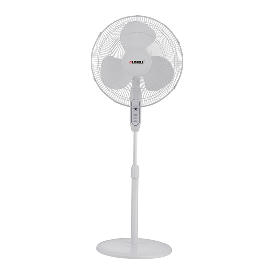
16" Stand Fan With Remote
Ventilateur de plancher de 40 cm avec télécommande
Ventilador de pie de 16" con control remoto
Mod
el
49251
/ Modèle / Modelo
READ AND SAVE THESE INSTRUCTIONS
VEUILLEZ LIRE CE MANUEL ET LE CONSERVER EN LIEU SÛR
LEA Y GUARDE ESTAS INSTRUCCIONES
Customer Service
1-866-646-4332
/ Service à la clientèle / Servicios al cliente:
1
LLR49251_UserManual.indd 1
10/26/18 3:17 PM
Table des Matières

Manuels Connexes pour Lorell 49251

Sommaire des Matières pour Lorell 49251
- Page 1 16" Stand Fan With Remote Ventilateur de plancher de 40 cm avec télécommande Ventilador de pie de 16" con control remoto 49251 / Modèle / Modelo READ AND SAVE THESE INSTRUCTIONS VEUILLEZ LIRE CE MANUEL ET LE CONSERVER EN LIEU SÛR...
-
Page 8: Consignes De Sécurité
ATTENTION Veuillez lire attentivement ces consignes avant d’utiliser votre nouvel appareil. AVERTISSEMENT 1. Afin d’éviter de causer une électrocution, cet appareil est doté d’une fiche polarisée (l’une des tiges est plus large). Elle ne peut donc être insérée dans une prise polarisée que d’une seule et unique façon. Si vous ne parvenez pas à insérer la fiche, retournez-la. - Page 9 DIRECTIVES D’INSTALLATION • Élément Arbre Moteur Alignez lors du montage Grillage arrière Serrez le bouton Poteau Base Crochet coudé Fig. 1 Conseil : Retirez les pièces avant de monter le ventilateur. LLR49251_UserManual.indd 9 10/26/18 3:17 PM...
- Page 10 Fig. 2 Montage Des Grillages Attache Grillage avant Contre-écrou pour les pales Pales Contre-écrou pour le grillage Fig. 3 LLR49251_UserManual.indd 10 10/26/18 3:17 PM...
-
Page 11: Affichage
• MONTAGE DU VENTILATEUR Montage de la Base 1. Alignez le poteau avec les encoches dans la base et fixez-les à l’aide du crochet coudé (voir la figure 4) 2. Posez l’unité motrice sur le poteau et resserrez l’anneau d’ajustement de la partie supérieure su poteau (voir la figure 1) 3. -
Page 12: Télécommande (Voir La Figure 6)
• TÉLÉCOMMANDE (voir la figure 6) Sélecteur de INTERRUPTEUR La télécommande comporte 3 boutons (voir la figure 6) VITESSE 1. Commande à distance MINUTERIE (a) Orientez la télécommande vers le ventilateur et appuyez sur la fonction désirée. (b) La télécommande fonctionne à une distance maximale de 5 mètres et à... -
Page 13: Consignes D'entretien
CONSIGNES D’ENTRETIEN 1. Débranchez l’appareil en tirant sur la fiche et non sur le fil d’alimentation. 2. Ouvrez le réceptacle du fusible sur la prise électrique en glissant le couvercle vers les broches. 3. Retirez le fusible avec précaution. Insérez la pointe du tournevis dans le porte-fusible et appuyez graduellement sur le manche pour déloger un côté... -
Page 20: Service & Support
SERVICE & SUPPORT In the event of a warranty claim or if service is required for this product, please contact us at the following: Toll Free: 1-866-646-4332 Email us at: customersupport@mideaamericacorp.com For questions or comments, please write to: Midea America Corporation Customer Care Center 11800 NW100th Rd.