Publicité
Les langues disponibles
Les langues disponibles
Liens rapides
Instructions for use and installation
GB
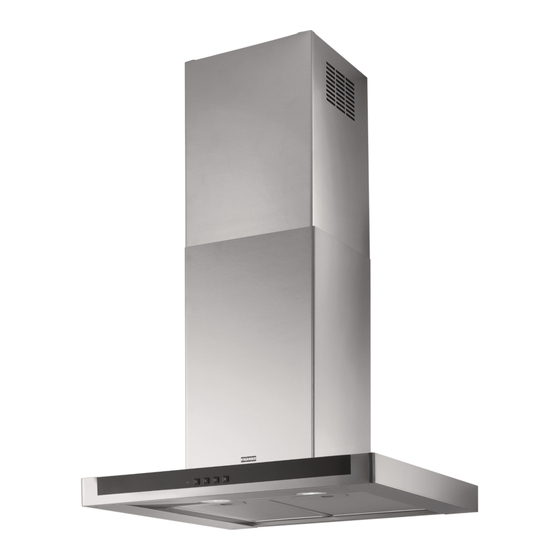
Cooker Hood
Istruzioni per l'uso e l'installazione
IT
Cappa
Mode d'emploi et installation
FR
Hotte de Cuisine
Bedienungsanleitung und Installation
DE
Dunstabzugshaube
Kullanım ve montaj talimatları
TR
Davlumbaz
Uživatelská Pøíruèka
CZ
Odsavač par
Instrukcja obsługi i instalacji
PL
Okap kuchenny
FNE 605 XS LED
FNE 905 XS LED
FNE 625 XS
FNE 925 XS
Publicité

Manuels Connexes pour Franke FNE 605 XS LED


Sommaire des Matières pour Franke FNE 605 XS LED
- Page 1 Mode d’emploi et installation Hotte de Cuisine Bedienungsanleitung und Installation Dunstabzugshaube Kullanım ve montaj talimatları Davlumbaz Uživatelská Pøíruèka Odsavač par Instrukcja obsługi i instalacji Okap kuchenny FNE 605 XS LED FNE 905 XS LED FNE 625 XS FNE 925 XS...
- Page 2 INDEX SAFETY INFORMATION ................................. 4 CHARACTERISTICS ................................7 INSTALLATION ..................................8 USE ...................................... 11 MAINTENANCE ................................... 12 INDICE INFORMAZIONI SULLA SICUREZZA ............................ 13 CARATTERISTICHE ................................16 INSTALLAZIONE ................................. 17 USO ...................................... 20 MANUTENZIONE................................. 21 SOMMAIRE CONSIGNES DE SÉCURITÉ ..............................22 CARACTERISTIQUES .................................
- Page 22 CONSIGNES DE SÉCURITÉ Pour votre sécurité et pour garantir le fonctionnement correct de l’appareil, veuillez lire attentivement ce manuel avant d’installer et de mettre en fonction l’appareil. Toujours conserver ces instructions avec l’appareil, même en cas de cession ou de transfert à une autre personne. Il est important que les utilisateurs connaissent toutes les caractéristiques de fonctionnement et de sécurité...
- Page 23 • Si vous utilisez l’aspirateur en même temps que des appareils non électriques (par ex. fonctionnant au gaz), veillez à ce que la pièce soit adéquatement ventilée, afin d’empêcher le retour du flux des gaz d’évacuation. Si vous utilisez la hotte de cuisine en même temps que des appareils non alimentés à l’électricité, la pression négative dans la pièce ne doit pas dépasser 0,04 mbar, afin d’éviter que les fumées soient réaspirées dans la pièce où...
- Page 24 • Cet appareil n’est pas destiné à être utilisé par des personnes (enfants compris) dont les capacités physiques, sensorielles ou mentales sont diminuées ou ayant une expérience et des connaissances insuffisantes, à moins que celles-ci ne soient attentivement surveillées et instruites. Les parties accessibles peuvent devenir très chaudes durant l’utilisation des appareils de cuisson.
- Page 25 CARACTERISTIQUES Encombrement Composants Réf. Q.té Composants de Produit Corps Hotte équipé de:Commandes, Lumière, Groupe Ventilateur,Filtres Cheminée Télescopique formée de : Cheminée Supérieure Cheminée Inférieure Flasque de Réduction ø 150-120 mm Raccord Sortie Air Réf. Q.té Composants pour l ’installation 7.2.1 Brides Fixation Cheminée Supérieure Chevilles Vis 4,2 x 44,4...
- Page 26 INSTALLATION Perçage Paroi et Fixation Brides 7.2.1 Tracer sur la paroi: • une ligne verticale allant jusqu’au plafond ou à la limite supérieure, au centre de la zone prévue pour le montage de la hotte; • une ligne horizontale à 650 mm min. au-dessus du plan de cuisson. •...
- Page 27 Montage Corps Hotte • Avant d’accrocher le corps hotte, serrer les deux vis Vr situées sur les points d’accrochage du corps hotte. • Accrocher le corps hotte aux vis 12a prévues à cet effet. • Serrer définitivement les vis 12a de support. •...
- Page 28 BRANCHEMENT ELECTRIQUE • Brancher la hotte sur le secteur en interposant un interrupteur bipolaire avec ouverture des contacts d’au moins 3 mm. • Enlever les filtres à graisse (voir § "Entretien") et s'assurer que le connecteur du câble d'alimentation soit bien branché dans la prise du diffuseur.
- Page 29 UTILISATION Tableau des commandes TOUCHE VOYANT FONCTIONS T1 Vitesse Allumé Démarre le moteur en première vitesse. Coupe le moteur. T2 Vitesse Allumé Démarre le moteur en deuxième vitesse. T3 Vitesse Fixe Appuyée brièvement, démarre le moteur en troisième vitesse. Lumière Branche et débranche l’éclairage.
- Page 30 ENTRETIEN Filtres anti-graisse NETTOYAGE FILTRES ANTI-GRAISSE METALLIQUES AUTOPORTEURS • Lavables au lave-vaisselle, ils doivent être lavés environ tous les 2 mois d’emploi ou plus fréquemment en cas d’emploi par- ticulièrement intense. • Retirer les filtres l’un aprés l’autre, en les poussant vers la par- tie arrière du groupe et en tirant simultanément vers le bas.
- Page 68 Franke S.p.a. Via Pignolini,2 37019 Peschiera del Garda (VR) www.franke.it 991.0450.230_ver3 – 180913 - D00002638_02...