Kessel Pumpfix Instructions D'installation, D'utilisation Et D'entretien
Table des Matières
Les langues disponibles
Les langues disponibles
Liens rapides
ANLEITUNG FÜR EINBAU, BETRIEB UND WARTUNG
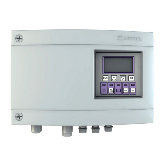
KESSEL-Schaltgerät Pumpfix / Ecolift
Installation
der Anlage wurde durchgeführt von Ihrem Fachbetrieb:
Name/Unterschrift
Stand 2019/04
All manuals and user guides at all-guides.com
Inbetriebnahme
Datum
Einweisung
Ort
Produktvorteile
Steckerfertige Anschlüsse
Mehrzeilige
Displayanzeige, intuitive
Menüführung
Selbstdiagnosesystem
Wartungsintervall mit
Erinnerung
USB-Schnittstelle
Optional: GSM-
Schnittstelle
Stempel Fachbetrieb
D
Seite 1
GB
Page 29
F
Page 57
I
Pagina 84
NL Pagina 112
PL Strona 140
Sach-Nr. 016-004
Chapitres
Table des Matières

Manuels Connexes pour Kessel Pumpfix


Sommaire des Matières pour Kessel Pumpfix
-
Page 56: Instructions De Pose, D'utilisation Et De Maintenance
All manuals and user guides at all-guides.com INSTRUCTIONS DE POSE, D‘UTILISATION ET DE MAINTENANCE Gestionnaire KESSEL Pumpfix / Ecolift Avantages du produit Prêt au raccordement Écran d‘affichage à plusieurs lignes, arborescence intuitive du menu Système d‘autodiagnostic Intervalle de maintenance avec fonction mémoire Port USB Option : interface GSM... - Page 57 All manuals and user guides at all-guides.com Sommaire Généralités Introduction et accueil ............................60 Description générale du produit .........................60 1.2.1 Plaque signalétique .............................61 1.2.2 Détail de livraison ..............................61 Informations d‘ordre général concernant ces instructions d‘utilisation et de maintenance ..62 Composants, éléments fonctionnels et raccordements ................62 1.4.1 Écran et panneau de commande, affichages .....................63 Sécurité...
- Page 58 All manuals and user guides at all-guides.com Adaptation de la longueur des câbles, mise à jour du logiciel Raccourcissement ou rallongement du câble de raccordement de la pompe / du détecteur ..79 Exportation de mises à jour et données......................79 6.2.1 Exportation de données ............................80 6.2.2 Mise à...
-
Page 59: Généralités
Chère cliente, Cher client, Nous vous félicitons de votre achat d‘un produit KESSEL. Ce produit sera certainement en mesure de répondre à toutes vos attentes. Nous vous souhaitons une mise en place sans faille et réussie. Nous tentons de maintenir un niveau de qualité aussi élevé que possible de nos produits et avons évidemment besoin de votre collaboration. -
Page 60: Plaque Signalétique
Accessoires de montage Gabarit de perçage Option Émetteur de signaux externe (Réf. # 20162) Boîtier à douille USB (Réf. # 28785) Fig. [2] Modem Kessel TeleControl (Réf. # 28792) Code d‘activation du contact sans potentiel (Réf. # 80077) 60 / 168 2019/04... -
Page 61: Informations D'ordre Général Concernant Ces Instructions D'utilisation Et De Maintenance
All manuals and user guides at all-guides.com Informations d‘ordre général concernant ces instructions d‘utilisation et de maintenance Pictogrammes et légendes utilisés <1> Information dans le texte attirant l‘attention sur un numéro de légende dans une figure Renvoi à une figure •... -
Page 62: Écran Et Panneau De Commande, Affichages
All manuals and user guides at all-guides.com 1.4.1 Écran et panneau de commande, affichages Position Désignation Fonction, description Écran Arborescence du men5.6voir 5.6 Diode d’état – Brillent : en service sous tension de réseau opérationnel – Éteintes : service sous tension de batterie (si l’écran affiche « Panne de secteur ») Diode d’alarme Clignotement : état d’alarme... -
Page 63: Sécurité
All manuals and user guides at all-guides.com Sécurité Utilisation conforme à l‘usage prévu Le gestionnaire est exclusivement destiné à commander des postes de relevage (DIN EN 12050, partie 1-3) et des clapets anti-retours avec pompe pour eaux grises et eaux-vannes*. L‘utilisation du gestionnaire dans des zones à... -
Page 64: Montage
All manuals and user guides at all-guides.com Montage Fixation du gestionnaire S’assurer que le gestionnaire a été coupé de l’alimentation en tension pendant les travaux de montage. • Choisir l‘emplacement prévu au montage en veillant aux points suivants : – Proximité directe du gestionnaire d‘une prise secteur avec terre. –... -
Page 65: Pose Du Port Usb Vers L'extérieur
All manuals and user guides at all-guides.com Pose du port USB vers l‘extérieur (Option) • Si prévu, poser le port USB vers l‘extérieur. Procéder comme décrit aux instructions jointes à la présente extension. Ill. [24] 2019/04 65 / 168... -
Page 66: Raccordement Des Connecteurs Et Câbles
All manuals and user guides at all-guides.com Raccordement des connecteurs et câbles Risque dû au dimensionnement erroné des conduites de raccordement. Le Pumpfix/Ecolift est exclusivement prévu pour une utilisation avec les conduites de raccordement fournies (ou des conduites équivalentes). Demander conseil au fabricant / fournisseur en cas de doute. - Page 67 Raccorder le connecteur du capteur de reflux (sonde optique de détection du niveau d’alarme dans la direction de la canalisation des eaux d‘égout) au raccordement <3> Affectation des câbles de raccordement: Fig. [9] (Pumpfix) ou Fig. [10] (Ecolift) Fig. [8] 2019/04...
- Page 68 All manuals and user guides at all-guides.com Variante Pumpfix Fig. [9] Variante Ecolift Fig. [10] 68 / 168 2019/04...
-
Page 69: Raccordement Du Contact Sans Potentiel
All manuals and user guides at all-guides.com 3.3.1 Raccordement du contact sans potentiel (Option) • Monter les manchons de bout pour torons (longueur de 8 mm) aux extrémités des câbles • Fixer le câble de raccordement suivant le schéma de raccordement à... -
Page 70: Première Mise En Service
La première mise en service impose de procéder aux saisies suivantes : 1. Langue de l’écran d‘affichage 2. Date / Heure 3. Type du produit – Configurations suivant le type du produit (Pumpfix F /Ecolift) 4. Intervalle de maintenance Mise en œuvre de l‘initialisation •... -
Page 71: Modification De L'intervalle D'autodiagnostic
Pour se faire, couper la tension d‘alimentation qui a pour effet d’établir l’état d’alarme ; la fonction est vérifiable Activation de l’alarme par textos • Procéder comme décrit aux instructions jointes à cet accessoire (Kessel TeleControl Modem) Contrôle fonctionnel • Vérifier l‘absence d’un message d‘erreur à l’écran •... -
Page 72: Service
All manuals and user guides at all-guides.com Service Mise en circuit • Établir l’alimentation en tension – Le gestionnaire exécute un autodiagnostic. – L‘écran affiche le type d‘appareil paramétré dans la configuration du système. – Si le système fonctionne correctement sans défaut, la diode verte qui signale que l’appareil est en ordre de marche <19>... -
Page 73: Message D'alarme En Cas De Panne De Secteur
All manuals and user guides at all-guides.com Message d‘alarme en cas de panne de secteur Une panne de secteur est identifiée par l’alimentation de la batterie du gestionnaire et signalée comme suit : – Alarme acoustique (bref signal à intervalles d’env. 20 secondes) –... -
Page 74: Commande Manuelle En Général
All manuals and user guides at all-guides.com Commande manuelle en général La manœuvre suivante est possible par commande manuelle : – Pompe d‘assainissement MARCHE / ARRÊT – Déplacement du clapet anti-retour à la position OUVERTE / FERMÉE 5.5.1 Commande manuelle de la pompe d‘assainissement 1. -
Page 75: Menu De Commande
All manuals and user guides at all-guides.com Ouverture du clapet anti-retour par commande manuelle Manœuvre uniquement possible si le clapet anti-retour a été fermé par une commande manuelle et en l’absence d’un reflux (la diode du clapet anti-retour <22> brille). • Appuyer sur la touche du clapet anti-retour <25> ;... - Page 76 All manuals and user guides at all-guides.com Arborescence du menu 0. Info système 1. Informations Heures de service 1.1.1 Durée totale 1.1.2 Panne de secteur 1.1.3 Consommation d‘énergie 1.1.4 Durée de la mise en charge 1.1.5 Nombre de mises en charge 1.1.6 Cycles du battant 1.1.7...
- Page 77 All manuals and user guides at all-guides.com 2.6.3 6 mois 2.6.4 12 mois 2.6.5 Maintenance manuelle Configurations Paramètres 3.1.1 Système d‘autodiagnostic SDS 3.1.2 Temporisation de mise en circuit du battant 3.1.3 Durée de fonctionnement par inertie du battant 3.1.4 Courant Courant du battant 3.1.5 Temporisation de mise en circuit de la pompe 3.1.6...
-
Page 78: Adaptation De La Longueur Des Câbles, Mise À Jour Du Logiciel
All manuals and user guides at all-guides.com Adaptation de la longueur des câbles, mise à jour du logiciel Attention au danger lié au courant électrique ! Les rééquipements décrits ci-après demeurent réservés au domaine de compétence exclusif d’électriciens agréés (voir 2.2). Raccourcissement ou rallongement du câble de raccordement de la pompe / du détecteur Rallonges disponibles (longueur de 10 m) –... -
Page 79: Exportation De Données
Afin que le port USB situé sur la platine soit aussi accessible sans l‘ouverture du boîtier, il est possible de commander un boîtier à douille USB, équipé d‘un câble et d‘un connecteur à intégrer dans le boîtier du gestionnaire chez KESSEL (voir 1.2.2). 2019/04... -
Page 80: Aide Au Diagnostic
All manuals and user guides at all-guides.com Aide au diagnostic Attention : danger de tension électrique en ouvrant le boîtier du gestionnaire. Les travaux sur les composants électriques demeurent réservés au domaine de compétence d‘électriciens qualifiés (voir 2.2). Affichage des pannes Cause Mesure d’arrêt Panne de batterie... -
Page 81: Caractéristiques Techniques
Dans ce cas, le Pumpfix/Ecolift serait prêt à fonctionner via un approvisionnement par batterie mais la batterie serait alors complètement vidée. -
Page 82: Déclaration De Conformité
All manuals and user guides at all-guides.com Déclaration de conformité 82 / 168 2019/04...