Lenze E82ZBU Mode D'emploi
Masquer les pouces
Voir aussi pour E82ZBU:
- Instructions de montage (12 pages) ,
- Instructions de montage (19 pages)
Les langues disponibles
Les langues disponibles
All manuals and user guides at all-guides.com
EDK82ZBU
00415671
06/00
Diese Anleitung
• beschreibt die Installation und die Handhabung der Schalter-Poti-Einheit.
• ist nur gültig
- für Schalter-Poti-Einheiten mit der Typenschildbezeichnung E82ZBU
- zusammen mit der Betriebsanleitung des zugehörigen Antriebsreglers.
Beschreibung
Die Schalter-Poti-Einheit E82ZBU ermöglicht
• die Vorgabe eines analogen Sollwertsignals für Lenze-Antriebsregler über die
Funktionsmodule Standard-I/O oder Application-I/O.
• die einfache Steuerung von Lenze-Antriebsreglern über die Digitaleingänge der
Funktionsmodule Standard-I/O oder Application-I/O (z. B. Drehrichtungsumkehr).
Einsatzbereich
Einsetzbar mit den Frequenzumrichter 8200 motec ab der Typenschildbezeichnung
E82MVxxx_4Bxxx 0x0x
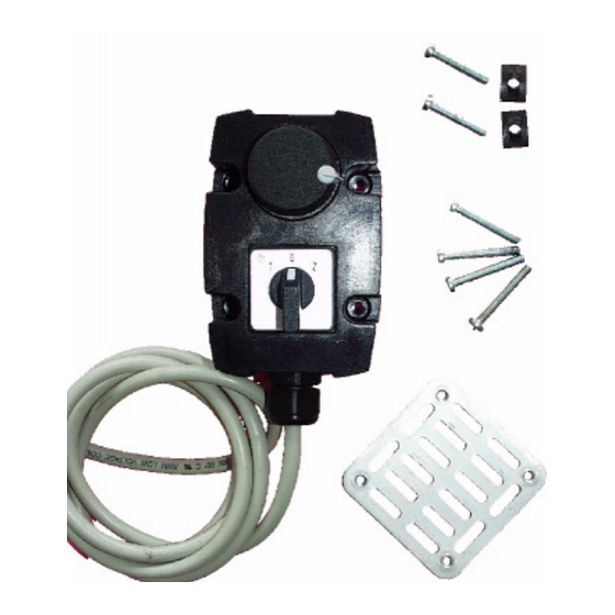
Lieferumfang
Allgemeine Daten und Einsatzbedingungen
Schutzart
Abmessungen (B x H x T)
Montagemöglichkeiten
Schalter-Poti-Einheit E82ZBU
für 8200 motec
1 Schalter-Poti-Einheit vorkonfektioniert mit 2,5 m Anschlußkabel
1 Befestigungsblech 60 mm x 60 mm
4 Schrauben M4 x 30 für die Befestigung der Schalter-Poti-Einheit
auf dem Befestigungsblech
2 Schrauben M4 x 20 mit Federblechen für die Befestigung am
Kühlkörper des motec
IP65
ca. 65 mm x 115 mm x 85 mm
am Kühlkörper des motec
(
Lenze GmbH & Co KG, Postfach 10 13 52, D-31763 Hameln
(+ 49) 5154 82-0, Fax Service: (+ 49) 5154 82-1112
an einer Wand
MA82ZBU 1.0
Table des Matières

Manuels Connexes pour Lenze E82ZBU


Sommaire des Matières pour Lenze E82ZBU
-
Page 11: Unité Potentiomètre-Interrupteur Type
L’unité potentiomètre-interrupteur E82ZBU permet • une entrée d’un signal de consigne analogique pour les variateurs de vitesse Lenze via les modules de fonction E/S standard et E/S application ; • une commande simplifiée des variateurs de vitesse Lenze via les entrées numériques des modules de fonction E/S standard ou E/S application (exemple :... -
Page 12: Installation Mécanique
All manuals and user guides at all-guides.com Installation mécanique L’unité potentiomètre-interrupteur peut être monté soit sur le radiateur du motec soit au mur. Fixation sur le radiateur du motec 4. Fixer la tôle de fixation avec 2 vis M4 x 20 et 2 tôles-ressorts sur le radiateur. -
Page 13: Câblage Avec E/S Standard
All manuals and user guides at all-guides.com Câblage avec E/S standard Entrée de la consigne via potentiomètre et inversion du sens de rotation (antihoraire - stop - horaire) via interrupteur Principe de fonctionnement • Après la coupure (STOP), la décélération s’effectue selon la rampe d’arrêt rapide (C0105). -
Page 14: Câblage Avec E/S Application
All manuals and user guides at all-guides.com Câblage avec E/S application Entrée de la consigne via potentiomètre et inversion du sens de rotation (antihoraire - stop - horaire) via interrupteur Principe de fonctionnement • Après la coupure (STOP), la décélération s’effectue selon la rampe d’arrêt rapide (C0105). -
Page 15: Autres Exemples D'application
All manuals and user guides at all-guides.com Autres exemples d’application Marche/arrêt (CINH) avec le module de fonction E/S standard Affectation des bornes X3/20 Fil brun Alimentation CC + 20 V X3/28 Fil blanc Marche/arrêt Fil vert = Non utilisé € Prévoir une isolation appropriée ! ó...