Black & Decker Workmate 225 Guide D'utilisation
Liens rapides
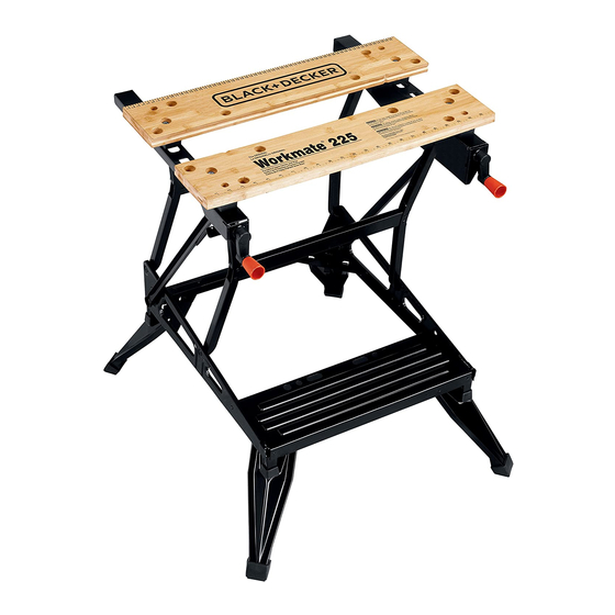
Workmate
225 tYPe 6
®
INSTRUCTION MANUAL
Catalog Number
WM225
TyPe 6
FRONT VISE JAW
M Â CHOIRE AVANT
MORDAZA FRONTAL
RELEASE LEVER
LEVIER DE D ÉCLENCHEMENT
PALANCA DE LIBERACIÓN
FOLDING LEGS
PIEDS ESCAMOTABLES
PATAS PLEGABLES
Thank you for choosing Black & Decker! To register your new product go to
www.BlackandDecker.com/NewOwner
Please reaD BefOre reTurNiNg This PrODucT fOr aNy reasON.
if you have a question or experience a problem with your Black & Decker purchase,
go to http://www.blackanddecker.com/instantanswers
if you can't find the answer or do not have access to the internet,
call 1-800-544-6986 from 8 a.m. to 5 p.m. esT Mon. - fri. to speak with an agent.
Please have the catalog number available when you call.
save This MaNual fOr fuTure refereNce.
vea el esPaNOl eN la cONTraPOrTaDa.
iNsTrucTivO De OPeraciÓN, ceNTrOs De serviciO y PÓliZa De garaNTÍa.
aDverTeNcia: lÉase esTe iNsTrucTivO aNTes De usar el PrODucTO.
FIG. 1
A.
FRAME
CADRE
BASTIDOR
B.
FRONT JAW
MÂCHOIRE AVANT
MORDAZA FRONTAL
C.
REAR JAW
MÂCHOIRE ARRIÈRE
MORDAZA TRASERA
D.
VISE SCREW
VIS D'ÉTAU
ESPARRAGO
E.
PIVOT NUT
ÉCROU DE PIVOT
TUERCA DE GIRO
F.
VISE CRANK
MANIVELLE D'ÉTAU
MANIVELA DE LA PRENSA
G.
CRANK HANDLE
POIGNÉE DE MANIVELLE
ASA DE LA MANIVELA
H.
SWIVEL PEGS
MORDACHES ORIENTABLES
TOPES GIRATORIOS
I.
SOCKET WRENCH
CLÉ À DOUILE
DADO
J.
FRONT TOP BLOCKS
CALES SUPÉRIEURES AVANT
BLOQUES DE REMATE FRONTALES
K.
REAR TOP BLOCKS
CALES SUPÉRIEURES ARRIÈRE
BLOQUES DE REMATE TRASEROS
L.
BOLTS
BOULONS
TORNILLOS
M.
PINS
CHEVILLES
PERNOS
N.
RUBBER FEET
BOUT DE CAOUTCHOUC
REGATONES DE GOMA
O.
WASHERS
RONDELLES
ARANDELAS
FIG. 7
FIG. 9
REAR JAW
M Â CHOIRE ARRIÈRE
MORDAZA TRASERA
CRANK
MANIVELLE
MANIVELA
SNAP-IN KNOBS
BOUTONS À ENCLENCHER
MANGOS DE LA MANIVELA
FOOTREST (NO STEP)
REPOSE-PIED (PAS UN MARCHEPIED)
DESCANSO PARA LOS PIES (NO ESCALON)
FIG. 2
FIG. 3
FIG. 4
FIG. 5
PDF created with FinePrint pdfFactory trial version
www.pdffactory.com
FIG. 6
RELEASE LEVER
LEVIER DE DÉCLENCHEMENT
PALANCA DE LIBERACIÓN
FIG. 8
FIG. 10
IMPORTANT SAFETY INSTRUCTIONS
1. Do not load with more than 450 pounds.
2. Do not apply an unbalanced load which could cause the work center to tip over.
3. Do not use the work center as a stepladder or standing platform. Do not use the lower
platform as a step when the work center is in "Workbench" position. The footboard is a
foot REST only.
4. Do not store work center outdoors or in a damp location.
5. Avoid applying excessive force when clamping with the swivel pegs.
6. Be sure that the legs are fully open (for workbench height) and be sure that the table
locks in position.
7. When using a power tool with the work center, follow the safety instructions in the
tool's instruction manual.
8. Always wear safety glasses when operating power tools.
9. An even pressure of the vise jaws on the workpiece is essential. Tighten both crank
handles uniformly.
SAVE THIS MANUAL FOR FUTURE REFERENCE
IMPORTANT SAFETY WARNINGS AND INSTRUCTIONS
TO REDUCE RISK OF INJURY:
• Before any use, be sure everyone using this tool reads and understands all safety
instructions and other information contained in this manual.
• Save these instructions and review frequently prior to use and in instructing others.
ASSEMBLY:
The Workmate ® 225 Type 6 work center comes partially assembled. A standard hammer
is required for assembly. A plastic socket wrench is included. Empty the contents of the
box and identify all components (see Figure 1). Place the frame (A) on the floor in the
position shown in Figure 1. Find the release levers near the front rubber feet on the sides
of the frame. Depress both release levers as shown in Figure 2 and pull up until you hear
the frame lock in place.
VISE JAW BRACKET:
1. Select the vise screws (D) and the pivot nuts (E). Screw one pivot nut onto each vise
screw about halfway as shown in Figure 3, assemble washer (O) on vise screw.
2. Insert the unthreaded end of the vise screws into the frame such that the pivot nuts
are located in the slots on the top of the frame and the unthreaded ends protrude
through the holes in the front of the frame, as shown in Figures 3 and 4.
3. Install the two vise cranks (F) and secure them by driving the pins (M) through the
holes in the cranks and the vise screws. (Align the holes in the vise cranks with the
holes in the vise screws and strike the pins sharply with a steel hammer until they
are flush with the sides of the vise cranks.) See Figure 5.
4. Closely examine the two front top blocks and the two rear ones. Note that the front
blocks do not have a protruding tab on the bottom side where the rear blocks do.
Select the front vise jaw, (B), and the two front top blocks, (J). Place the top blocks
on the rails of the frame as shown in Figure 6.
5. Install the front vise jaw on top of the top blocks so that the small holes at each end
of the jaw fit down over the posts on the top side of the blocks. With the jaw
positioned as described above insert into the frame as shown in Figure 6, insert two
of the four bolts, (L) into the holes in the jaw and tighten them securely into the holes
in the pivot nut. Use the socket wrench, (I) provided, shown in Figure 1.
NOTE: For clarity, only the left side assembly is shown. Perform all operations
on right side as well.
6. Select the rear vise jaw, (C) and the two rear top blocks, (K). Position the rear top blocks
A.
on the frame rails so that the tab ears in the bottom of the blocks fit into the key holes
FRAME
of the frame rail. Position the top blocks so their raised posts are toward the rear of the
CADRE
BASTIDOR
frame, as shown in Figure 7. Now install the rear vise jaw so that the small holes in the
ends of the jaw fit over the raised posts on the top blocks you just installed.
7. Insert the remaining two bolts, (L) into the holes in the jaw and through the top
D.
blocks into the raised posts of the vise guides. The holes in the rear blocks are not
VISE SCREW
VIS D'ÉTAU
threaded so you will feel resistance as you cut threads into them.
ESPARRAGO
8. Snap-in crank handle as shown in Figure 8.
F.
9. To assemble the rubber feet to your Workmate: Turn the unit upside down. Swing
VISE CRANK
out the four legs to the fully extended and locked position. Align the rubber foot with
MANIVELLE D'ÉTAU
MANIVELA DE LA PRENSA
the leg as shown in Figure 9. Lightly tap foot into place with a hammer.
H.
CHANGING THE INDEXED POSITION OF THE REAR JAW:
SWIVEL PEGS
MORDACHES ORIENTABLES
1. Install the rear jaw in 1 of 3 possible indexed "keyhole" positions by indexing the rear
TOPES GIRATORIOS
vise jaw into a keyhole in the vise jaw bracket. Secure the rear jaw by sliding it to the
K.
back of the keyhole. As shown in Figure 7.
FRONT TOP BLOCKS
CALES SUPÉRIEURES AVANT
SWIVEL PEGS:
BLOQUES DE REMATE FRONTALES
1. The four supplied swivel pegs can be used in any of the holes in the front and rear
M.
jaws. The pegs are used to extend the dimensions of your Workmate's holding
BOLTS
BOULONS
capacity. (Figure 10)
TORNILLOS
O.
SERVICE INFORMATION
RUBBER FEET
Black & Decker offers a full network of company-owned and Authorized Service
BOUT DE CAOUTCHOUC
locations throughout North America. All Black & Decker Service Centers are staffed with
REGATONES DE GOMA
trained personnel to provide customers with efficient and reliable power tool
service. Whether you need technical advice, repair, or genuine factory replacement
parts, contact the Black & Decker service location nearest you. To find your local
service location, refer to the yellow page directory under "Tools—Electric" or call:
1-800-54-HOW-TO.
LIMITED TWO-YEAR HOME USE WARRANTY
Black & Decker (U.S.) Inc. warrants this product for two years against any defects
in material or workmanship. The defective product will be replaced or repaired at no
charge in either of two ways: The first, which will result in exchanges only, is to return
the product to the retailer from whom it was purchased (provided that the store is a
participating retailer). Returns should be made within the time period of the retailer's
policy for exchanges (usually 30 to 90 days after the sale). Proof of purchase may be
required. Please check with the retailer for their specific return policy regarding returns
that are beyond the time set for exchanges. The second option is to take or send the
product (prepaid) to a Black & Decker owned or Authorized Service Center for repair or
replacement at our option. Proof of purchase may be required. Black & Decker owned
and Authorized Service Centers are listed under "Tools-Electric" in the yellow pages of
the phone directory. This warranty does not apply to accessories. This warranty gives
you specific legal rights and you may have other rights which vary from state to state.
Should you have any questions, contact the manager of your nearest Black & Decker
Service Center. This product is not intended for commercial use.
Imported by
Black & Decker (U.S.) Inc.,
701 E. Joppa Rd.
Towson, MD 21286
U.S.A.
AVANT DE RETOURNER LE PRODUIT, PEU IMPORTE LA RAISON, PRéRE DE
1. Ne jamais placer une charge supérieure à 204 kg (450 lb) sur l'étau-établi.
2. Ne jamais placer sur l'étau-établi une charge mal équilibrée qui pourrait le faire basculer.
3. Ne jamais se servir de l'étau-établi comme marchepied ni comme plate-forme. Ne
pas monter sur la plate-forme inférieure lorsque l'étau-établi est en position d'établi.
Le repose-pied sert seulement à se REPOSER les pieds.
4. Ne pas ranger l'étau-établi à l'extérieur ni dans un endroit humide.
5. Éviter de trop serrer les mâchoires des mordaches orientables.
6. S'assurer que les pieds sont pleinement écartés et que le plateau est verrouillé en
position de chevalet.
7. Respecter les consignes de sécurité contenues dans les guides d'utilisation des
outils électriques utilisés avec l'étau-établi.
8. Toujours porter des lunettes de sécurité lorsqu'on utilise des outils électriques.
READ ALL INSTRUCTIONS
B.
FRONT JAW
MÂCHOIRE AVANT
MORDAZA FRONTAL
C.
REAR JAW
MÂCHOIRE ARRIÈRE
MORDAZA TRASERA
E.
PIVOT NUT
ÉCROU DE PIVOT
TUERCA DE GIRO
G.
CRANK HANDLE
POIGNÉE DE MANIVELLE
ASA DE LA MANIVELA
J.
SOCKET WRENCH
CLÉ À DOUILE
DADO
L.
REAR TOP BLOCKS
CALES SUPÉRIEURES ARRIÈRE
BLOQUES DE REMATE TRASEROS
N.
PINS
CHEVILLES
PERNOS
P.
WASHERS
RONDELLES
ARANDELAS
GUIDE D'UTILISATION
Modèle WM225
COMPROSER LE 1 800 544 6986
IMPORTANTES MESURES DE SéCURITé
See 'Tools-
Electric'
– Yellow Pages –
for Service &
Sales

Manuels Connexes pour Black & Decker Workmate 225


Sommaire des Matières pour Black & Decker Workmate 225
- Page 1 IMPORTANT SAFETY INSTRUCTIONS 1. Do not load with more than 450 pounds. 2. Do not apply an unbalanced load which could cause the work center to tip over. 3. Do not use the work center as a stepladder or standing platform. Do not use the lower platform as a step when the work center is in “Workbench”...
- Page 2 9. Les mâchoires doivent exercer une pression uniforme sur la pièce à ouvrer, il faut • Antes de cualquier uso, asegúrese que toda persona que vaya a utilizar esta donc les serrer également. herramienta lea y comprenda todas las instrucciones de seguridad y demás información contenida en este manual. CONSERVER CES MESURES à TITRE DE RéFéRENCE • Conserve estas instrucciones y repáselas con frecuencia antes de utilizar la unidad AFIN DE RéDUIRE LES RISQUES DE BLESSURES y de instruir a terceros.