Table des Matières

Publicité

Les langues disponibles
  • FR

Les langues disponibles

Liens rapides

EDK94AYCET
.G?#
L−force Communication
EtherCAT
E94AYCET
Kommunikationsmodul
Communication module
Module de communication
Módulo de comunicaciones
Modulo di comunicazione
Montageanleitung
Mounting Instructions
Instructions de montage
Instrucciones para el montaje
Istruzioni per il montaggio
l

Publicité

Table des Matières
loading

Sommaire des Matières pour Lenze L-force Communication

  • Page 1 EDK94AYCET L−force Communication .G?# Montageanleitung Mounting Instructions Instructions de montage Instrucciones para el montaje Istruzioni per il montaggio EtherCAT E94AYCET Kommunikationsmodul Communication module Module de communication Módulo de comunicaciones Modulo di comunicazione...
  • Page 3 Lesen Sie zuerst diese Anleitung, bevor Sie mit den Arbeiten beginnen! Beachten Sie die enthaltenen Sicherheitshinweise. Please read these instructions before you start working! Follow the enclosed safety instructions. Veuillez lire attentivement cette documentation avant toute action ! Les consignes de sécurité doivent impérativement être respectées. Lea las instrucciones antes de empezar a trabajar.
  • Page 4 E94AYCET001B 0Abb. 0Tab. 0 E94AYCET017 EDK94AYCET DE/EN/FR/ES/IT 5.1...
  • Page 5 Pos. Beschreibung Ausführliche Information ^ 20 X245 Anschluss für externe Spannungsversorgung 2−polige Steckerleiste mit Federkraftanschluss ^ 18 X246 EtherCAT−Anschluss, Eingang (IN) RJ45−Buchse nach IEC 60603−7 ^ 18 X247 EtherCAT−Anschluss, Ausgang (OUT) RJ45−Buchse nach IEC 60603−7 ^ 22 LED−Statusanzeigen zur Diagnose EDK94AYCET DE/EN/FR/ES/IT 5.1...
  • Page 6: Table Des Matières

    Inhalt Über diese Dokumentation ......... . Verwendete Konventionen .
  • Page 7: Über Diese Dokumentation

    E94AYCET 03.00 Zielgruppe Diese Dokumentation richtet sich an Personen, die die Vernetzung und Fernwartung einer Maschine projektieren, installieren, in Betrieb nehmen und warten. Tipp! Informationen und Hilfsmittel rund um die Lenze−Produkte finden Sie im Download−Bereich unter www.lenze.com EDK94AYCET DE/EN/FR/ES/IT 5.1...
  • Page 8: Verwendete Konventionen

    Über diese Dokumentation Verwendete Konventionen Verwendete Konventionen Diese Dokumentation verwendet folgende Konventionen zur Unterscheidung verschiede- ner Arten von Information: Informationsart Auszeichnung Beispiele/Hinweise Zahlenschreibweise Dezimaltrennzeichen Punkt Es wird generell der Dezimalpunkt verwendet. Beispiel: 1234.56 Symbole Seitenverweis Verweis auf eine andere Seite mit zu- sätzlichen Informationen Beispiel: 16 = siehe Seite 16...
  • Page 9: Verwendete Hinweise

    Über diese Dokumentation Verwendete Hinweise Verwendete Hinweise Um auf Gefahren und wichtige Informationen hinzuweisen, werden in dieser Dokumenta- tion folgende Piktogramme und Signalwörter verwendet: Sicherheitshinweise Aufbau der Sicherheitshinweise: Gefahr! (kennzeichnet die Art und die Schwere der Gefahr) Hinweistext (beschreibt die Gefahr und gibt Hinweise, wie sie vermieden werden kann) Piktogramm und Signalwort Bedeutung Gefahr von Personenschäden durch gefährliche elektri-...
  • Page 10 Über diese Dokumentation Verwendete Hinweise Anwendungshinweise Piktogramm und Signalwort Bedeutung Wichtiger Hinweis für die störungsfreie Funktion Hinweis! Nützlicher Tipp für die einfache Handhabung Tipp! Verweis auf andere Dokumentation EDK94AYCET DE/EN/FR/ES/IT 5.1...
  • Page 11: Sicherheitshinweise

    Sicherheitshinweise Sicherheitshinweise Gefahr! Unsachgemäßer Umgang mit dem Kommunikationsmodul und dem Grundgerät kann schwere Personenschäden und Sachschäden verursachen. Beachten Sie die in der Dokumentation zum Grundgerät enthaltenen Sicherheitshinweise und Restgefahren. Stop! Elektrostatische Entladung Durch elektrostatische Entladung können elektronische Bauteile innerhalb des Kommunikationsmoduls beschädigt oder zerstört werden.
  • Page 12: Produktbeschreibung

    Produktbeschreibung Funktion Produktbeschreibung Funktion Das Kommunikationsmodul koppelt Lenze Servo Drives 9400 an das Kommunikationssys- tem EtherCAT. Bestimmungsgemäße Verwendung Das Kommunikationsmodul ... ƒ ist eine Zubehör−Baugruppe, die mit folgenden Lenze Grundgeräten eingesetzt werden kann: Produktreihe Typenbezeichnung ab Hardwarestand ab Softwarestand Servo Drives 9400 HighLine E94AxHxxxx 01.51...
  • Page 13: Identifikation

    Produktbeschreibung Identifikation Identifikation E94AYCET005  ‚ ƒ 03.00 Produktreihe Gerätegeneration Modulkennung: Erweiterungsmodul Modultyp: Kommunikationsmodul EtherCAT Hardwarestand Softwarestand EDK94AYCET DE/EN/FR/ES/IT 5.1...
  • Page 14: Technische Daten

    Technische Daten Allgemeine Daten Technische Daten Allgemeine Daten Bereich Werte Bestell−Bezeichnung E94AYCET Kommunikationsprofil EtherCAT Kommunikationsmedium S/FTP (Screened Foiled Twisted Pair, ISO/IEC 11801 oder EN 50173), CAT 5e Schnittstelle RJ45: Standard Ethernet (nach IEEE 802.3), 100Base−TX (Fast Ether- net) Netzwerktopologie Linie, Switch Teilnehmeranzahl max.
  • Page 15: Abmessungen

    Technische Daten Abmessungen Abmessungen E94YCXX005 89 mm 134 mm 87 mm 23 mm EDK94AYCET DE/EN/FR/ES/IT 5.1...
  • Page 16: Mechanische Installation

    Mechanische Installation Mechanische Installation Montage E94YCXX001G Demontage E94AYCXX001H EDK94AYCET DE/EN/FR/ES/IT 5.1...
  • Page 17: Elektrische Installation

    Elektrische Installation EMV−gerechte Verdrahtung Elektrische Installation EMV−gerechte Verdrahtung In typischen Anlagen ist die standardmäßige Schirmung der Ethernet−Kabel ausreichend. In sehr stark gestörten Umgebungen kann eine Verbesserung der EMV−Festigkeit durch eine zusätzliche beidseitige Erdung des Kabelschirms ermöglicht werden. Beachten Sie dazu folgende Hinweise: 1.
  • Page 18: Ethercat−Anschluss

    Elektrische Installation EtherCAT−Anschluss EtherCAT−Anschluss Zum Anschluss des Kommunikationsmoduls an den Feldbus eignet sich ein handelsübli- ches Standard−Ethernet−Patchkabel (siehe "Spezifikation des Ethernet−Kabels" (^ 19)). Hinweis! Um Beschädigungen der RJ45−Buchse zu vermeiden, den Stecker des Ethernet−Kabels gerade (im rechten Winkel) in die Buchse stecken bzw. aus der Buchse ziehen.
  • Page 19 Elektrische Installation EtherCAT−Anschluss Spezifikation des Ethernet−Kabels Hinweis! Verwenden Sie ausschließlich Kabel, die den aufgeführten Spezifikationen entsprechen. Spezifikation des Ethernet−Kabels Ethernet−Standard Standard Ethernet (nach IEEE 802.3), 100Base−TX (Fast Ethernet) Kabeltyp S/FTP (Screened Foiled Twisted Pair), ISO/IEC 11801 oder EN 50173, CAT 5e Dämpfung 23.2 dB (bei 100 MHz und je 100 m) Nebensprechdämpfung...
  • Page 20: Externe Spannungsversorgung

    Elektrische Installation Externe Spannungsversorgung Externe Spannungsversorgung Hinweis! Verwenden Sie bei externer Spannungsversorgung und bei größeren Entfernungen zwischen den Schaltschränken in jedem Schaltschrank immer ein separates und nach EN 61800−5−1 sicher getrenntes Netzteil ("SELV"/"PELV"). Die externe Spannungsversorgung des Kommunikationsmoduls ist notwendig, wenn beim Ausfall der Versorgung des Grundgerätes die EtherCAT−Kommunikation bestehen bleiben soll.
  • Page 21: Inbetriebnahme

    Inbetriebnahme Vor dem ersten Einschalten Inbetriebnahme Vor dem ersten Einschalten Stop! Bevor Sie das Grundgerät mit dem Kommunikationsmodul erstmalig einschalten, überprüfen Sie die gesamte Verdrahtung auf Vollständigkeit, Kurzschluss und Erdschluss. Kommunikationshandbuch E94AYCET (EtherCAT) Hier finden Sie ausführliche Informationen zur Inbetriebnahme des Kommunikationsmoduls.
  • Page 22: Diagnose

    Diagnose LED−Statusanzeigen Diagnose LED−Statusanzeigen Zur Störungsdiagnose stehen für das EtherCAT−Modul die auf der Frontseite angeordneten LEDs zur Verfügung. Hinweis! Im normalen Betrieb ... sollten nur die LEDs "MS" und "BS" permanent leuchten. ƒ muss an den RJ45−Buchsen X246 und X247 jeweils die grüne LED leuchten ƒ...
  • Page 23 Diagnose LED−Statusanzeigen Pos. Farbe Zustand Beschreibung Beschreibung grün Das Kommunikationsmodul ist am Feldbus nicht aktiv oder befin- det sich im Zustand "Init". blinkt 200 ms 200 ms Zustand "Pre−Operational" aktiv: Zugriff auf Parameter und Objekte möglich. Kein Prozessdatenaustausch blinkt 1−mal 1000 ms 1000 ms 200 ms...
  • Page 24 Diagnose LED−Statusanzeigen E94YCET001E Pos. Farbe Zustand Beschreibung grün Physikalische EtherCAT−Verbindung ist vorhanden. flackert 50 ms Daten werden über EtherCAT ausgetauscht. Diese LED wird nicht verwendet. EDK94AYCET DE/EN/FR/ES/IT 5.1...
  • Page 25 Diagnose LED−Statusanzeigen EDK94AYCET DE/EN/FR/ES/IT 5.1...
  • Page 26 E94AYCET001B 0Fig. 0Tab. 0 E94AYCET017 EDK94AYCET DE/EN/FR/ES/IT 5.1...
  • Page 27 Pos. Description Detailed information ^ 42 X245 Terminal for external voltage supply 2−pin plug connector with spring connection ^ 40 X246 EtherCAT connection, input (IN) RJ45 socket in accordance with IEC 60603−7 ^ 40 X247 EtherCAT connection, output (OUT) RJ45 socket in accordance with IEC 60603−7 ^ 44 LED status displays for diagnostics EDK94AYCET DE/EN/FR/ES/IT 5.1...
  • Page 28 Contents About this documentation ......... . . Conventions used .
  • Page 29: About This Documentation

    Target group This documentation addresses to persons who project, install, commission, and maintain the networking and remote maintenance of a machine. Tip! Information and tools concerning the Lenze products can be found in the download area under www.lenze.com EDK94AYCET DE/EN/FR/ES/IT 5.1...
  • Page 30: Conventions Used

    About this documentation Conventions used Conventions used This documentation uses the following conventions to distinguish between different types of information: Type of information Identification Examples/notes Numbers Decimal separator Point The decimal point is used throughout this documentation. Example: 1234.56 Symbols Page reference Reference to another page with additional information...
  • Page 31: Notes Used

    About this documentation Notes used Notes used The following pictographs and signal words are used in this documentation to indicate dangers and important information: Safety instructions Structure of safety instructions: Danger! (characterises the type and severity of danger) Note (describes the danger and gives information about how to prevent dangerous situations) Pictograph and signal word Meaning...
  • Page 32 About this documentation Notes used Application notes Pictograph and signal word Meaning Important note to ensure troublefree operation Note! Useful tip for simple handling Tip! Reference to another documentation EDK94AYCET DE/EN/FR/ES/IT 5.1...
  • Page 33: Safety Instructions

    Safety instructions Safety instructions Danger! Inappropriate handling of the communication module and the standard device can cause serious personal injury and material damage. Observe the safety instructions and residual hazards described in the documentation for the standard device. Stop! Electrostatic discharge Electronic components of the communication module can be damaged or destroyed through electrostatic discharge.
  • Page 34: Product Description

    The communication module couples Lenze Servo Drives 9400 with the EtherCAT communication system. Application as directed The communication module ... ƒ is an accessory module which can be used in conjunction with the following Lenze standard devices: Product range Type designation...
  • Page 35: Identification

    Product description Identification Identification E94AYCET005  ‚ ƒ 03.00 Product range Version Module ID: extension module Module type: communication module EtherCAT Hardware version Software version EDK94AYCET DE/EN/FR/ES/IT 5.1...
  • Page 36: Technical Data

    Technical data General data Technical data General data Field Values Order designation E94AYCET Communication profile EtherCAT Communication medium S/FTP (Screened Foiled Twisted Pair, ISO/IEC 11801 or EN 50173), CAT 5e Interface RJ45: Standard Ethernet (in accordance with IEEE 802.3), 100base−TX (fast Ethernet) Network topology Line, switch...
  • Page 37: Dimensions

    Technical data Dimensions Dimensions E94YCXX005 89 mm 134 mm 87 mm 23 mm EDK94AYCET DE/EN/FR/ES/IT 5.1...
  • Page 38: Mechanical Installation

    Mechanical installation Mechanical installation Mounting E94YCXX001G Dismounting E94AYCXX001H EDK94AYCET DE/EN/FR/ES/IT 5.1...
  • Page 39: Electrical Installation

    Electrical installation EMC−compliant wiring Electrical installation EMC−compliant wiring In typical systems, standard shielding of the Ethernet cables is sufficient. In environments with a very high level of interference, immunity to noise can be improved by additionally earthing the cable shield on both sides. Observe the following notes for this: 1.
  • Page 40: Ethercat Connection

    Electrical installation EtherCAT connection EtherCAT connection You can use a standard Ethernet patch cable for connecting the communication module to the fieldbus (see "Ethernet cable specifications" (^ 41)). Note! Plug/remove the Ethernet cable plug in a straight manner (at right angles) into/from the socket to make sure that the RJ45 socket will not be damaged.
  • Page 41 Electrical installation EtherCAT connection Ethernet cable specifications Note! Only use cables complying with the below specifications. Ethernet cable specifications Ethernet standard Standard Ethernet (according to IEEE 802.3), 100base TX (fast Ethernet) Cable type S/FTP (Screened Foiled Twisted Pair), ISO/IEC 11801 or EN 50173, CAT 5e Damping 23.2 dB (at 100 MHz and per 100 m)
  • Page 42: External Voltage Supply

    Electrical installation External voltage supply External voltage supply Note! Always use a separate power supply unit in every control cabinet and safely separate it according to EN 61800−5−1 ("SELV"/"PELV") in the case of external voltage supply and larger distances between the control cabinets. The external voltage supply of the communication module is required if EtherCAT communication is to remain intact in case the supply of the standard device fails.
  • Page 43: Commissioning

    Commissioning Before switching on Commissioning Before switching on Stop! Before switching on the standard device with the communication module for the first time, check the entire wiring for completeness, short circuit and earth fault. E94AYCET (EtherCAT) communication manual Here you’ll find some detailed information on commissioning the communication module.
  • Page 44: Diagnostics

    Diagnostics LED status displays Diagnostics LED status displays For fault diagnostics the LEDs on the front are provided for the EtherCAT module. Note! During normal operation ... only the LEDs "MS" and "BS" should be lit constantly. ƒ The green LED at the RJ45 sockets X246 and X247 must be lit or blinking. ƒ...
  • Page 45 Diagnostics LED status displays Pos. Colour Condition Description Description green The communication module is not active on the fieldbus or is in the "Init" status. blinking 200 ms 200 ms "Pre−operational" status active: Access to parameters and objects possible. No process data exchange blinking 1000 ms 1000 ms...
  • Page 46 Diagnostics LED status displays E94YCET001E Pos. Colour Condition Description green Physical EtherCAT connection is available. flickering 50 ms Data are exchanged via EtherCAT. This LED is not used. EDK94AYCET DE/EN/FR/ES/IT 5.1...
  • Page 47 Diagnostics LED status displays EDK94AYCET DE/EN/FR/ES/IT 5.1...
  • Page 48 E94AYCET001B 0Fig. 0Tab. 0 E94AYCET017 EDK94AYCET DE/EN/FR/ES/IT 5.1...
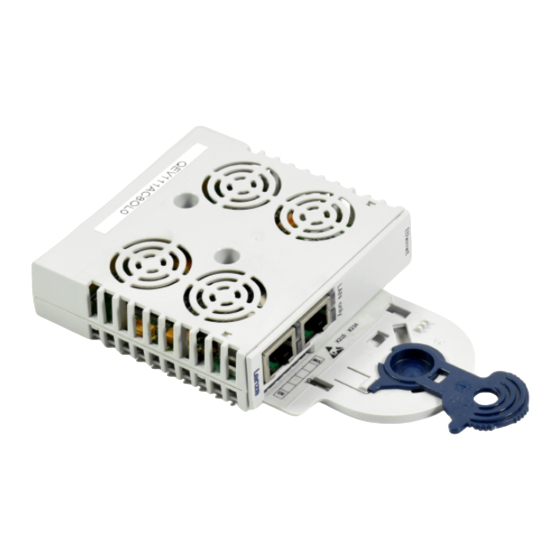
  • Page 49 Pos. Description Informations détaillées ^ 64 X245 Raccordement pour alimentation externe Bornier à lame ressort, à 2 broches ^ 62 X246 Raccordement EtherCAT, entrée (IN) Prise RJ45 selon CEI 60603−7 ^ 62 X247 Raccordement EtherCAT, sortie (OUT) Prise RJ45 selon CEI 60603−7 ^ 66 Affichage d’état par LED pour le diagnostic EDK94AYCET DE/EN/FR/ES/IT 5.1...
  • Page 50 Sommaire Présentation du document ......... . . Conventions utilisées .
  • Page 51: Présentation Du Document

    Cette documentation s’adresse aux personnes chargées de la conception, de l’installation, de la mise en service et de mise en réseau et de la télémaintenance d’une machine. Conseil ! Toutes les informations relatives aux produits Lenze peuvent être téléchargées sur notre site à l’adresse suivante : www.Lenze.com...
  • Page 52: Conventions Utilisées

    Présentation du document Conventions utilisées Conventions utilisées Pour distinguer les différents types d’information, cette documentation utilise les conventions suivantes : Type d’information Aperçu Exemples/remarques Représentation des chiffres Séparateur décimal Point Le point décimal est généralement utilisé. Exemple : 1234.56 Pictogrammes Renvoi à...
  • Page 53: Consignes Utilisées

    Présentation du document Consignes utilisées Consignes utilisées Pour indiquer des risques et des informations importantes, la présente documentation utilise les mots et pictogrammes suivants : Consignes de sécurité Présentation des consignes de sécurité Danger ! (Le pictogramme indique le type de risque.) Explication (L’explication décrit le risque et les moyens de l’éviter.) Pictogramme et mot associé...
  • Page 54: Remarque Importante

    Présentation du document Consignes utilisées Consignes d’utilisation Pictogramme et mot associé Explication Remarque Remarque importante pour assurer un fonctionnement correct importante ! Conseil utile pour faciliter la mise en œuvre Conseil ! Renvoi à une autre documentation EDK94AYCET DE/EN/FR/ES/IT 5.1...
  • Page 55: Consignes De Sécurité

    Consignes de sécurité Consignes de sécurité Danger ! Toute utilisation non conforme à la fonction du module de communication et de l’appareil de base risque d’entraîner des blessures graves et des dommages matériels. Tenir compte des consignes de sécurité et des dangers résiduels indiqués dans la documentation de l’appareil de base.
  • Page 56: Description Du Produit

    Description du produit Fonction Description du produit Fonction Le module de communication relie les appareils Servo Drives 9400 de Lenze au système de communication EtherCAT. Utilisation conforme à la fonction Le module de communication ... ƒ est un accessoire compatible avec les appareils de base Lenze suivants : Série d’appareils...
  • Page 57: Identification

    Description du produit Identification Identification E94AYCET005  ‚ ƒ 03.00 Série d’appareils Génération d’appareils Identification du module : module d’extension Type de module : module de communication EtherCAT Version matérielle Version logicielle EDK94AYCET DE/EN/FR/ES/IT 5.1...
  • Page 58: Spécifications Techniques

    Spécifications techniques Caractéristiques générales Spécifications techniques Caractéristiques générales Domaine Valeurs Référence de commande E94AYCET Profil de communication EtherCAT Support de communication S/FTP (Screened Foiled Twisted Pair, ISO/CEI 11801 ou EN 50173), CAT 5e Interface RJ45 : Ethernet standard (selon IEEE 802.3), 100Base−TX (Fast Ethernet) Topologie du réseau Ligne, commutateur (switch)
  • Page 59: Encombrements

    Spécifications techniques Encombrements Encombrements E94YCXX005 89 mm 134 mm 87 mm 23 mm EDK94AYCET DE/EN/FR/ES/IT 5.1...
  • Page 60: Installation Mécanique

    Installation mécanique Installation mécanique Montage E94YCXX001G Démontage E94AYCXX001H EDK94AYCET DE/EN/FR/ES/IT 5.1...
  • Page 61: Installation Électrique

    Installation électrique Câblage conforme CEM Installation électrique Câblage conforme CEM Dans les installations types, un blindage standard du câble Ethernet suffit. Dans les environnements soumis à de fortes perturbations, il est possible d’améliorer la résistance CEM par une mise à la terre supplémentaire du blindage du câble. Tenir compte des consignes suivantes : 1.
  • Page 62: Raccordement Ethercat

    Installation électrique Raccordement EtherCAT Raccordement EtherCAT Le module de communication peut être raccordé au bus de terrain à l’aide d’un câble droit Ethernet standard en vente dans le commerce (voir "Spécifications du câble Ethernet" (^ 63)). Remarque importante ! Enficher ou retirer le connecteur du câble Ethernet verticalement (angle droit) afin d’éviter tout endommagement de la prise RJ45.
  • Page 63 Installation électrique Raccordement EtherCAT Spécifications du câble Ethernet Remarque importante ! Utiliser exclusivement des câbles conformes aux spécifications indiquées. Spécifications du câble Ethernet Standard Ethernet Ethernet standard (selon IEEE 802.3), 100Base−TX (Fast Ethernet) Type de câble S/FTP (Screened Foiled Twisted Pair), ISO/CEI 11801 ou EN 50173, CAT 5e Atténuation 23.2 dB (pour 100 MHz et par segment de 100 m)
  • Page 64: Alimentation Externe

    Installation électrique Alimentation externe Alimentation externe Remarque importante ! En cas d’alimentation externe et de distances importantes entre les armoires électriques, toujours utiliser un bloc d’alimentation avec coupure de sécurité ("SELV"/"PELV") distinct et conforme à la norme EN 61800−5−1 pour chaque armoire électrique.
  • Page 65: Mise En Service

    Mise en service Avant la première mise sous tension Mise en service Avant la première mise sous tension Stop ! Avant la première mise sous tension de l’appareil de base avec le module de communication, vérifier si le câblage a été correctement réalisé dans son intégralité...
  • Page 66: Diagnostic

    Diagnostic Affichages d’état par LED Diagnostic Affichages d’état par LED Les LED situées sur la face avant du module EtherCAT servent au diagnostic des erreurs. Remarque importante ! Dans les conditions normales de fonctionnement ... seules les LED "MS" et "BS" sont allumées en continu. ƒ...
  • Page 67 Diagnostic Affichages d’état par LED Pos. Couleur Etat Description Description Vert Le module de communication n’est pas activé au niveau du bus de terrain ou se trouve à l’état "Init". Clignote 200 ms 200 ms Etat "Pre−Operational" activé : Accès possible aux paramètres et aux objets Pas d’échange de données process Clignote 1000 ms...
  • Page 68 Diagnostic Affichages d’état par LED E94YCET001E Pos. Couleur Etat Description Vert Liaison EtherCAT physique établie Clignote rapidement 50 ms (scintille) Echange de données via EtherCAT Rouge Cette LED n’est pas utilisée. EDK94AYCET DE/EN/FR/ES/IT 5.1...
  • Page 69 Diagnostic Affichages d’état par LED EDK94AYCET DE/EN/FR/ES/IT 5.1...
  • Page 70 E94AYCET001B 0Fig. 0Tab. 0 E94AYCET017 EDK94AYCET DE/EN/FR/ES/IT 5.1...
  • Page 71 Pos. Descripción Información detallada ^ 85 X245 Conexión para suministro de voltaje externo Regleta de conectores de 2 polos con conexión por fuerza de resorte ^ 83 X246 Conexión EtherCAT, entrada (IN) Conector hembra RJ45 según IEC 60603−7 ^ 83 X247 Conexión EtherCAT, salida (OUT) Conector hembra RJ45 según IEC 60603−7...
  • Page 72 Contenido Acerca de esta documentación ........Convenciones utilizadas .
  • Page 73: Acerca De Esta Documentación

    Esta documentación está dirigida a aquellas personas que se encargan de la planificación, instalación, puesta en servicio y mantenimiento de la interconexión y el mantenimiento remoto de un equipo. ¡Sugerencia! Encontrará información y consejos sobre los productos de Lenze en el área de descargas en www.lenze.com EDK94AYCET DE/EN/FR/ES/IT 5.1...
  • Page 74: Convenciones Utilizadas

    Acerca de esta documentación Convenciones utilizadas Convenciones utilizadas Esta documentación utiliza las siguientes convenciones para distinguir diferentes tipos de información: Tipo de información Marcación Ejemplos/indicaciones Números Separador decimal Punto En general se usa el punto decimal. Ejemplo: 1234.56 Símbolos Referencia de página Referencia con información adicional sobre otra página Ejemplo:...
  • Page 75: Indicaciones Utilizadas

    Acerca de esta documentación Indicaciones utilizadas Indicaciones utilizadas Para indicar peligros e información importante, se utilizan en esta documentación los siguientes términos indicativos y símbolos: Instrucciones de seguridad Estructura de las instrucciones de seguridad: ¡Peligro! (indican el tipo y la gravedad del peligro) Texto indicativo (describe el peligro y da instrucciones para evitarlo) Pictograma y término indicativo...
  • Page 76: Instrucciones De Seguridad

    Instrucciones de seguridad Instrucciones de seguridad ¡Peligro! El uso inapropiado del módulo de comunicaciones y del equipo básico puede causar accidentes y daños materiales. Observe las Instrucciones de Seguridad y Riesgos Residuales contenidos en la documentación del equipo básico. ¡Alto! Descarga electrostática A causa de una descarga electrostática podrían resultar dañados o destruidos componentes electrónicos dentro del módulo de comunicaciones.
  • Page 77: Descripción Del Producto

    El módulo de comunicaciones conecta Lenze Servo Drives 9400 al sistema de comunicaciones EtherCAT. Uso previsto El módulo de comunicaciones... ƒ es un accesorio que puede conectarse con el siguiente equipo básico Lenze: Serie Denominación de tipo A partir de la versión A partir de la versión...
  • Page 78: Identificación

    Descripción del producto Identificación Identificación E94AYCET005  ‚ ƒ 03.00 Serie Generación de equipos Identificación del módulo: Módulo de ampliación Tipo de módulo: Módulo de comunicaciones EtherCAT Versión de hardware Versión de software EDK94AYCET DE/EN/FR/ES/IT 5.1...
  • Page 79: Datos Técnicos

    Datos técnicos Datos generales Datos técnicos Datos generales Área Valores Referencia para pedidos E94AYCET Perfil de comunicación EtherCAT Medio de comunicación S/FTP (Screened Foiled Twisted Pair, ISO/IEC 11801 o EN 50173), CAT Interfaz RJ45: Standard Ethernet (según IEEE 802.3), 100Base−TX (Fast Ethernet) Topología de red Línea, switch...
  • Page 80: Dimensiones

    Datos técnicos Dimensiones Dimensiones E94YCXX005 89 mm 134 mm 87 mm 23 mm EDK94AYCET DE/EN/FR/ES/IT 5.1...
  • Page 81: Instalación Mecánica

    Instalación mecánica Instalación mecánica Montaje E94YCXX001G Desmontaje E94AYCXX001H EDK94AYCET DE/EN/FR/ES/IT 5.1...
  • Page 82: Instalación Eléctrica

    Instalación eléctrica Cableado correcto CEM Instalación eléctrica Cableado correcto CEM En instalaciones típicas es suficiente el apantallado estándar de los cables Ethernet. En instalaciones con fuertes interferencias se puede mejorar la resistencia CEM mediante una puesta a tierra adicional de la malla del cable a ambos lados. Para ello, observe las siguientes indicaciones: 1.
  • Page 83: Conexión A Ethercat

    Instalación eléctrica Conexión a EtherCAT Conexión a EtherCAT Para la conexión del módulo de comunicaciones al bus de campo es adecuado el uso del cable patch Ethernet estándar disponible en los comercios (véase "Especificación del cable Ethernet" (^ 84)). ¡Aviso! Para evitar daños en el conector RJ45, inserte y extraiga el conector del cable Ethernet de forma recta (en ángulo recto) respecto al conector correspondiente.
  • Page 84 Instalación eléctrica Conexión a EtherCAT Especificación del cable Ethernet ¡Aviso! Sólo utilice cables conforme a las especificaciones indicadas. Especificación del cable Ethernet Ethernet Estándar Ethernet estándar (según IEEE 802.3), 100Base−TX (Fast Ethernet) Tipo de cable S/FTP (Screened Foiled Twisted Pair), ISO/IEC 11801 o EN 50173, CAT 5e Atenuación 23.2 dB (a 100 MHz y cada 100 m)
  • Page 85: Voltaje De Alimentación Externo

    Instalación eléctrica Voltaje de alimentación externo Voltaje de alimentación externo ¡Aviso! En caso de que exista un voltaje de alimentación externo y que haya una gran distancia entre los armarios de distribución, utilice en cada armario de distribución una fuente de alimentación independiente y con separación segura conforme a EN 61800−5−1 («SELV»/«PELV»).
  • Page 86: Puesta En Marcha

    Puesta en marcha Antes de la primera conexión Puesta en marcha Antes de la primera conexión ¡Alto! Antes de poner en marcha por primera vez el equipo básico con el módulo de comunicaciones, compruebe que todo el cableado esté completo y que no haya cortocircuitos ni contactos a tierra.
  • Page 87: Diagnóstico

    Diagnóstico Indicadores de estado LED Diagnóstico Indicadores de estado LED Para el diagnóstico de fallos, el módulo EtherCAT dispone de LED, que se encuentran en la cara frontal del equipo. ¡Aviso! En funcionamiento normal... sólo deben estar encendidos de forma constante los LED "MS" y "BS"; ƒ...
  • Page 88 Diagnóstico Indicadores de estado LED Pos. Color Estado Descripción Descripción rojo encendido Se ha detectado un error en el área del módulo de comunicaciones. verde apagado El módulo de comunicaciones no está activo en el bus de campo o se encuentra en estado "Init". parpadea 200 ms 200 ms...
  • Page 89 Diagnóstico Indicadores de estado LED E94YCET001E Pos. Color Estado Descripción verde encendido La conexión física de EtherCAT está disponible. centellea 50 ms Se están intercambiando datos a través de EtherCAT. rojo apagado Este LED no se utiliza. EDK94AYCET DE/EN/FR/ES/IT 5.1...
  • Page 90 E94AYCET001B 0Fig. 0Tab. 0 E94AYCET017 EDK94AYCET DE/EN/FR/ES/IT 5.1...
  • Page 91 Pos. Descrizione Informazioni dettagliate ^ 105 X245 Collegamento per alimentazione esterna Morsettiera estraibile a 2 poli con collegamento a molla ^ 103 X246 Collegamento EtherCAT, ingresso (IN) Connettore femmina RJ45 secondo IEC 60603−7 ^ 103 X247 Collegamento EtherCAT, uscita (OUT) Connettore femmina RJ45 secondo IEC 60603−7 ^ 107 Indicatori di stato a LED per diagnostica...
  • Page 92 Sommario Informazioni sul manuale ..........Convenzioni utilizzate .
  • Page 93: Informazioni Sul Manuale

    La presente documentazione è rivolta al personale responsabile della progettazione, installazione, messa in servizio e manutenzione dei collegamenti di rete e del telecontrollo di una macchina. Suggerimento: Per informazioni e ausili sui prodotti Lenze, consultare l’area Download all’indirizzo www.lenze.com EDK94AYCET DE/EN/FR/ES/IT 5.1...
  • Page 94: Convenzioni Utilizzate

    Informazioni sul manuale Convenzioni utilizzate Convenzioni utilizzate La presente documentazione utilizza le seguenti convenzioni tipografiche per distinguere i diversi tipi di informazioni: Tipo di informazione Convenzione Esempi/Note tipografica Modalità di scrittura dei numeri Separatore decimale Punto Generalmente si utilizza il punto decimale.
  • Page 95: Avvertenze Utilizzate

    Informazioni sul manuale Avvertenze utilizzate Avvertenze utilizzate Per segnalare pericoli ed informazioni importanti, nella presente documentazione sono riportati i seguenti simboli e parole di segnalazione: Note di sicurezza Struttura delle note di sicurezza: Pericolo! (indica il tipo e la gravità del pericolo) Testo della nota (descrive il pericolo e fornisce indicazioni su come può...
  • Page 96: Informazioni Sulla Sicurezza

    Informazioni sulla sicurezza Informazioni sulla sicurezza Pericolo! Un utilizzo improprio del modulo di comunicazione e del dispositivo base può causare gravi danni materiali e alle persone. Rispettare le informazioni sulla sicurezza e sugli altri pericoli contenute nella documentazione relativa al dispositivo base. Stop! Scariche elettrostatiche Eventuali scariche elettrostatiche possono danneggiare o distruggere le...
  • Page 97: Descrizione Del Prodotto

    Descrizione del prodotto Funzione Descrizione del prodotto Funzione Il modulo di comunicazione collega i Servo Drives 9400 Lenze al sistema di comunicazione EtherCAT. Utilizzo conforme Il modulo di comunicazione ... ƒ è un modulo accessorio che può essere impiegato con i seguenti dispositivi base...
  • Page 98: Identificazione

    Descrizione del prodotto Identificazione Identificazione E94AYCET005  ‚ ƒ 03.00 Serie Versione Identificazione modulo: modulo di espansione Tipo di modulo: modulo di comunicazione EtherCAT Versione hardware Versione software EDK94AYCET DE/EN/FR/ES/IT 5.1...
  • Page 99: Dati Tecnici

    Dati tecnici Dati generali Dati tecnici Dati generali Campo Valori Denominazione per l’ordine E94AYCET Profilo di comunicazione EtherCAT Mezzo di comunicazione S/FTP (Screened Foiled Twisted Pair, ISO/IEC 11801 o EN 50173), CAT 5e Interfaccia RJ45: Standard Ethernet (secondo IEEE 802.3), 100Base−TX (Fast Ethernet) Topologia di rete Lineare, Switch...
  • Page 100: Dimensioni

    Dati tecnici Dimensioni Dimensioni E94YCXX005 89 mm 134 mm 87 mm 23 mm EDK94AYCET DE/EN/FR/ES/IT 5.1...
  • Page 101: Installazione Meccanica

    Installazione meccanica Installazione meccanica Montaggio E94YCXX001G Smontaggio E94AYCXX001H EDK94AYCET DE/EN/FR/ES/IT 5.1...
  • Page 102: Installazione Elettrica

    Installazione elettrica Cablaggio conforme EMC Installazione elettrica Cablaggio conforme EMC Nei normali impianti è sufficiente una schermatura standard del cavo Ethernet. In ambienti con forti interferenze, per migliorare l’immunità EMC è possibile realizzare un ulteriore collegamento a terra su entrambi i lati della schermatura del cavo. Per questo, osservare quanto segue: 1.
  • Page 103: Collegamento Ethercat

    Installazione elettrica Collegamento EtherCAT Collegamento EtherCAT Per il collegamento del modulo di comunicazione al bus di campo è possibile utilizzare un cavo patch Ethernet standard, reperibile in commercio (vedere "Specifiche del cavo Ethernet" (^ 104)). Avvertenza: Per evitare danni alla presa RJ45, inserire il connettore del cavo Ethernet nella presa o estrarlo da quest’ultima in verticale (perpendicolarmente).
  • Page 104 Installazione elettrica Collegamento EtherCAT Specifiche del cavo Ethernet Avvertenza: Utilizzare esclusivamente cavi conformi alle specifiche. Specifiche del cavo Ethernet Ethernet standard Ethernet standard (secondo IEEE 802.3), 100Base−TX (Fast Ethernet) Tipo di cavo S/FTP (Screened Foiled Twisted Pair), ISO/IEC 11801 o EN 50173, CAT 5e Attenuazione 23.2 dB (a 100 MHz e ogni 100 m)
  • Page 105: Alimentazione Esterna

    Installazione elettrica Alimentazione esterna Alimentazione esterna Avvertenza: In caso di alimentazione esterna e di distanze elevate tra gli armadi elettrici, utilizzare sempre in ciascun armadio elettrico un alimentatore separato e con isolamento sicuro secondo la norma EN 61800−5−1 ("SELV/PELV"). L’alimentazione esterna del modulo di comunicazione è necessaria qualora in caso di guasto/mancanza dell’alimentazione del dispositivo base la comunicazione EtherCAT debba comunque rimanere attiva.
  • Page 106: Messa In Servizio

    Messa in servizio Prima dell’accensione Messa in servizio Prima dell’accensione Stop! Prima di accendere per la prima volta il dispositivo base con il modulo di comunicazione collegato, verificare l’integrità del cablaggio e l’assenza di cortocircuiti e dispersioni a terra. Manuale di comunicazione E94AYCET (EtherCAT) In questa documentazione sono riportate informazioni dettagliate sulla messa in servizio del modulo di comunicazione.
  • Page 107: Diagnostica

    Diagnostica Indicatori di stato a LED Diagnostica Indicatori di stato a LED Per la diagnostica dei problemi al modulo EtherCAT sono disponibili i LED disposti sul lato frontale. Avvertenza: In condizioni di funzionamento normale... devono essere accessi permanentemente solo i LED "MS" e "BS" ƒ...
  • Page 108 Diagnostica Indicatori di stato a LED Pos. Colore Stato Descrizione Descrizione verde spento Il modulo di comunicazione non è attivo nel bus di campo o si trova nello stato "Init". lampeggia 200 ms 200 ms Stato "Pre−Operational" attivo: È possibile accedere a parametri ed oggetti. Nessuno scambio di dati di processo lampeggia 1000 ms...
  • Page 109 Diagnostica Indicatori di stato a LED E94YCET001E Pos. Colore Stato Descrizione verde acceso Il collegamento fisico EtherCAT è presente. jitter 50 ms È attivo lo scambio di dati via EtherCAT. rosso spento Questo LED non viene utilizzato. EDK94AYCET DE/EN/FR/ES/IT 5.1...
  • Page 110 ã C Q © 03/2015 Lenze Automation GmbH Service Lenze Service GmbH Postfach 10 13 52, 31763 Hameln Breslauer Straße 3, D−32699 Extertal Hans−Lenze−Str. 1, 31855 Aerzen GERMANY Germany HR Hannover B 205381 +49 5154 82−0 008000 2446877 (24 h helpline) Ê...

Ce manuel est également adapté pour:

EthercatE94aycet

Table des Matières