DK2 POWER OPS240 Guide De L'utilisateur
Fendeuse à bois énergie cinétique de 40 tonnes
Table des Matières
Les langues disponibles
Les langues disponibles
Liens rapides
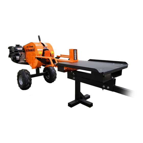
OPS240
40 TON KINETIC LOG SPLITTER
ATV TOWABLE • 1 SECOND RAM SPEED • 7HP KOHLER ENGINE
IMPORTANT
Please read the safety rules and assembly instructions carefully before
assembling and operating this machine.
USER MANUAL
DK2 USA WEST
DK2 CORPORATE OFFICE
DK2 USA EAST
4301 S VALLEY VIEW BLVD.
5330 MAINWAY
3750 SOUTH AVENUE
SUITE 10-11 LAS VEGAS, NEVADA
BURLINGTON, ONTARIO
NORTH UNIT, TOLEDO, OHIO
89103 USA
L7L6A4 CANADA
43615 USA
PARTS AND SERVICE 1 (888) 277-6960 | WWW.DETAILK2.COM
Chapitres
Table des Matières
Dépannage

Sommaire des Matières pour DK2 POWER OPS240
- Page 37 OPS240 FENDEUSE À BOIS ÉNERGIE CINÉTIQUE DE 40 TONNES REMORQUABLE PAR VTT • 1 SECONDE VITESSE DE BÉLIER • MOTEUR KOHLER 7CV IMPORTANT Veuillez lire attentivement les règles de sécurité et les instructions de montage avant l’assemblage et faire fonctionner cette machine.
- Page 38 GARANTIE ..............36 2 | OPS240 man.
-
Page 39: Spécifications Mécaniques
SPÉCIFICATIONS MÉCANIQUES Démarreur manuel Moteur 7CV 4 temps, 3600 RPM Puissance Essence Commande Commande à deux mains Hauteur de la bûche 8 pouces (20cm) Capacité de bûche 22 po. longueur et diamètre maximum Temps de cycle Environ 1 seconde Pneu 6.5-8, 4.0-8, 4.8-8 Taux de pignon Volant-moteur Max Tr/min... - Page 40 SECTION I RÈGLES DE SÉCURITÉ...
-
Page 41: Conventions Sur La Sécurité
LES RÈGLES DE SÉCURITÉ CONVENTIONS DE SÉCURITÉ AVERTISSEMENT : Ceci indique une situation dangereuse qui, si elle n’est pas évitée, pourrait entraîner la mort ou des blessures graves. ATTENTION : Ceci indique une situation dangereuse qui, si elle n’est pas évitée, pourrait entraîner un blessure mineure ou modérée. -
Page 42: Étiquettes De Mise En Garde
Éloignez tous les enfants de la fendeuse à bois. Ne marchez d'utiliser la fendeuse. d'e ectuer l'opération d'entretien. pas sur la fendeuse à bois. Utilisez uniquement les mains pour actionner le levier de la soupape de commande. 6 | OPS240 man. -
Page 43: Personnes Et Animaux
LES RÈGLES DE SÉCURITÉ PERSONNES ET ANIMAUX ATTENTION : PROTÉGEZ-VOUS ET CEUX QUI VOUS ENTOURENT Il s’agit d’une machine de grande puissance, avec des pièces mobiles fonctionnant à haute énergie. Vous devez utiliser la machine en toute sécurité. Un fonctionnement dangereux peut créer un certain nombre de dangers pour vous, ainsi que quelqu’un d’autre dans les environs. -
Page 44: Essence
Le retrait de telles pièces pourrait créer un risque d’incendie. N’utilisez pas de solutions inflammables pour nettoyer le filtre à air. Le silencieux et le moteur deviennent très chauds et peuvent provoquer de graves brûlures ; Ne pas toucher. 8 | OPS240 man. -
Page 45: Sécurité Générale
LES RÈGLES DE SÉCURITÉ SÉCURITÉ GÉNÉRALE AVERTISSEMENT : SÉCURITÉ GÉNÉRALE L’utilisation de cette fendeuse à bois en toute sécurité est nécessaire pour prévenir ou minimiser le risque de mort ou de blessure. Un fonctionnement dangereux peut créer un certain nombre de dangers pour vous. - Page 46 REMARQUE : La liste des avertissements et des mises en garde ne peut pas être complète. Si des situations qui ne sont pas couvertes par ce manuel, l’opérateur doit faire preuve de bon sens et utiliser cette fendeuse de manière sûre. Contactez les revendeurs pour obtenir de l’aide dans votre région. 10 | OPS240 man.
- Page 47 SECTION II MONTAGE...
-
Page 48: Étape 1 : Inspecter L'emballage
Le Splitter est expédié dans une caisse. Retirez tous les côtés avant de commencer. REMARQUE : Lors de l’inspection des pièces, si vous constatez des dommages ou des pièces manquantes, veuillez appeler DK2 POWER au 1 (888) 277-6960 ou contactez-nous via notre site internet à www.detailk2.com. On remplacera gratuitement toute pièce endommagée ou manquante. -
Page 49: Étape 2 : Cadre Transversal Et Cadre De Barre De Remorquage
MONTAGE INSTRUCTIONS ÉTAPE PAR ÉTAPE ÉTAPE 2 : CADRE TRANSVERSAL ET CADRE DE LA BARRE DE REMORQUAGE Installez le cadre transversal et le cadre de la barre de remorquage. Utilisez 4 boulons inclus pour assembler. 4 X BOULONS ET ÉCROUS v.210823 | 13... -
Page 50: Étape 3 : Levier De Contrôle De Verrouillage De Sécurité
MONTAGE INSTRUCTIONS ÉTAPE PAR ÉTAPE ÉTAPE 3 : LEVIER DE CONTRÔLE VERROUILLAGE DE SÉCURITÉ OUVREZ LE COUVERCLE ET INSTALLEZ LA POIGNÉE VERROUILLABLE DE CONTRÔLE DE SÉCURITÉ. VISSER JUSQU’A CE QUELLE SOIT SERRER DANS LA BARRURE. 14 | OPS240 man. -
Page 51: Étape 4 : Levier De Fente
MONTAGE INSTRUCTIONS ÉTAPE PAR ÉTAPE ÉTAPE 4 : LEVIER DE FENTE Installez la levier de fente avec le matériel fourni. Fermez et verrouillez le capot. PLACER L’ÉCROU DE CE CÔTÉ v.210823 | 15... -
Page 52: Étape 5 : Support
ÉTAPE 5 : SUPPORT Installez le support. Boulonnez dans le trou inférieur. Goupille d’attelage dans le trou supérieur. 1 GOUPILLE D’ATTELAGE SUR LE DESSUS 1 BOULON EN BAS LEVER LORS DU REMORQUAGE UTILISER LA GOUPILLE D’ATTELAGE TROU INFÉRIEUR 16 | OPS240 man. -
Page 53: Étape 6 : Barre De Remorquage
MONTAGE INSTRUCTIONS ÉTAPE PAR ÉTAPE ÉTAPE 6 : BARRE DE REMORQUAGE UTILISATION DES 2 BOULONS FOURNIS, SÉCURISÉS LA BARRE DE REMORQUAGE DANS L’ASSEMBLAGE v.210823 | 17... -
Page 54: Étape 7 : Support De Table Avant
ÉTAPE 7 : SUPPORT DE LA TABLE AVANT Installez le support de table avant comme indiqué à l’aide de la quincaillerie fournie. Gardez libre non serré jusqu’après l’installation de la table pour faciliter l’alignement des trous. UTILISER LE MATÉRIEL INCLUS POUR FIXER 18 | OPS240 man. -
Page 55: Étape 8 : Fixation Des Roues À L'essieu
MONTAGE INSTRUCTIONS ÉTAPE PAR ÉTAPE ÉTAPE 8 : FIXATION DES ROUES À L’ESSIEU Installez les roues sur l’essieu et insérez la goupille à ressort. Assurez-vous que la roue tourne librement. Vous pouvez retirer la goupille, faire glisser la roue et la re-barrer pour bloquer la roue pendant l’utilisation de la fendeuse. v.210823 | 19... - Page 56 à chaîne, et tenez l’unité à la verticale, reposant sur la plaque de fond arrière. ATTENTION, CET APPAREIL EST LOURD ET DOIT ÊTRE MANIPULÉ PAR PLUSIEURS PERSONNES OU UN APPAREIL DE LEVAGE SÉCURITAIRE. Insérez les 4 boulons fournis et serrez. 20 | OPS240 man.
-
Page 57: Étape 10 : Glissières Du Berceau De Bûches
MONTAGE INSTRUCTIONS ÉTAPE PAR ÉTAPE ÉTAPE 10 : GLISSIÈRES DU BERCEAU DE BÛCHES Assemblez les glissières du berceau de bûches sur le côté de la poutre comme illustré ci- dessous. Utilisez le matériel fourni et boulonnez les deux de berceau de rail ensemble. Serrez bien tous les boulons. -
Page 58: Étape 11 : Table De Travail
REMARQUE : Graissez les dents de la crémaillère et la cannelure avec de la graisse standard. Gardez la poutre de fente libre de graisse et gardée propre lors du fendage. Le bélier glisse sur une plaque de téflon, alors gardez-le propre , sans graisse et des particules de bois. 22 | OPS240 man. - Page 59 SECTION III FONCTIONNEMENT...
-
Page 60: Pratiques De Sécurité Et Informations Générales
Chargez la bûche sur la poutre, glissez jusqu’au coin de fente. • Portez des lunettes de sécurité, des gants et des chaussures de protection. • Utilisez uniquement à l’extérieur - les vapeurs de gaz sont mortelles à l’intérieur. 24 | OPS240 man. - Page 61 FONCTIONNEMENT PRATIQUES DE SÉCURITÉ ET INFORMATIONS GÉNÉRALES INFORMATIONS GÉNÉRALES Faites tourner le moteur à plein régime. Cette machine pousse le vérin vers l’avant pendant 1/2 seconde et se rétracte pendant encore 1/2 seconde. Pour assurer une bonne utilisation de la fendeuse, laissez la machine se rétracter avant de charger une autre bûche.
-
Page 62: Avant De Commencer
à embout d’acier aux chaussures. Familiarize yourself with the correct and incorrect methods of splitting logs. Never split a log using an incorrect or unsafe method. 26 | OPS240 man. -
Page 63: Démarrage Et Arrêt
FONCTIONNEMENT DÉMARRAGE ET ARRÊT DÉMARRAGE Positionnez votre fendeuse sur un sol plat et sec, puis barrez la roue avant avec le frein, assurez-vous que la machine ne peut pas être déplacée à partir de cette position. Assurez-vous que le robinet de carburant est ouvert en position ON. Déplacez le levier de commande de l’étrangleur sur la position CHOKE (ne devrait être nécessaire que si le moteur est froid). -
Page 64: Zone Opération
Avec votre main gauche, tirez le levier de sécurité, avec votre main droite, poussez le levier de fendage, puis laissez aller. Cette machine se rétracte automatiquement après relâchement du levier de fendage. 28 | OPS240 man. - Page 65 SECTION IV ENTRETIEN...
-
Page 66: Liste De Contrle Régulière
Graisseur à crémaillère et pignon • Vérifier la pression des pneus • Nettoyer l’extérieur du moteur et les • ailettes de refroidissement du moteur Changez l’huile du moteur • Remplacer le filtre à air • Remplacer la bougie • 30 | OPS240 man. -
Page 67: Informations Générales
ENTRETIEN INFORMATIONS GÉNÉRALES ENTRETIEN MOTEUR Reportez-vous au manuel de votre moteur Kohler fourni pour plus d’instructions sur l’entretien du moteur. AVIS : LUBRIFICATION Tous les roulements de votre fendeuse sont des unités scellées et doivent avoir une quantité suffisante de lubrifiant pour durer toute la vie de votre machine avec une utilisation normale. AVIS : GRAISSAGE DE LA CRÉMAILLÈRE ET DU PIGNON Toutes les crémaillères et pignons doivent être graissés avant chaque utilisation avec de la graisse pour engrenages standard. -
Page 68: Dépannage
• Nettoyez les copeaux de bois ou autres débris du dessous du panier. n’engage pas la • Nettoyez la saleté accumulée du cadre où l’ensemble de chariot repose contre les pare-chocs en crémaillère avec caoutchouc pignon. 32 | OPS240 man. - Page 69 SECTION V PIÈCES & SCHÉMAS...
-
Page 70: Vue Explosée
PIÈCES & SCHÉMAS VUE EXPLOSÉE 34 | OPS240 man. -
Page 71: Liste Des Pièces
Tige de transmission Goupille de support avant Poutre Ressort de torsion Goupille de déclenchement Scannez le code QR pour accéder au magasin de pièces DK2 POWER ou ouvrez votre navigateur et accédez à www.detailk2.com/shop-power-equipment-parts Votre modèle de déchiqueteuse est : OPS240... -
Page 72: Garantie
Detail K2 réparera, remplacera ou fournira toute pièce défectueuse couverte par la garantie à notre gré. La Garantie de DK2 POWER est de 1 an sur les pièces seulement Cette garantie ne s’applique pas à la main-d’oeuvre. La garantie Kohler de 3 ans est PIÈCES et MAIN-D’OEUVRE.