Carel ir33 Mode D'emploi
Masquer les pouces
Voir aussi pour ir33:
- Mode d'emploi (60 pages) ,
- Manuel d'utilisation (11 pages) ,
- Manuel simplifié (10 pages)
+0500009ML - rel 1.2 - 10.12.2010
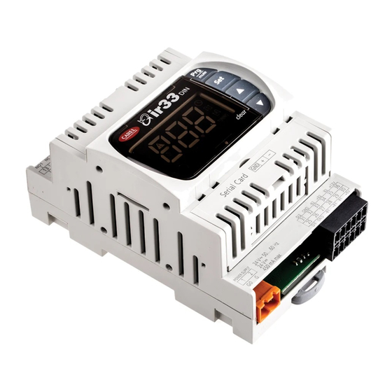
ir33 Universale Multi-Input
TIPO / TYPE
CODICE / CODE
DESCRIZIONE / DESCRIPTION
1 relay
DN33V9xxxx(*)
Universal 2 Multi input, 1 relay, buzzer, IR
2 relay
DN33W9xxx (*)
Universal 2 Multi input, 2 relay, buzzer, IR
4 relay
DN33Z9xxxx(*)
Universal 2 Multi input, 4 relay, buzzer, IR
4 SSR
DN33A9xxxx(*)
Universal 2 Multi input, 4 SSR, buzzer, IR
1 relè + 1 0...10 Vdc
DN33B9xxxx(*)
Universal 2 Multi input, 1 relay + 1 AO, buzzer, IR
2 relè + 2 0...10 Vdc
DN33E9xxxx(*)
Universal 2 Multi input, 2 relay + 2 AO, buzzer, IR
(*) xxxx= HR20: alimentazione/power supply = 115...230 Vac
xxxx= HB20: orologio (RTC) e alimentazione/real time clock (RTC) and power supply = 115...230 Vac
xxxx= MR20: alimentazione/power supply = 24 Vac, 24 Vdc
Dimensioni (mm) / Dimensions (mm)
70
60
Connessioni opzionali / Optional connections
Interfaccia seriale RS485.
Serial board RS485.
Interfaccia seriale RS485
Serial board RS485
Chiave di programmazione
Programming key
Schema elettrico / Wiring diagram:
NO1 NC1
C1
NO3 NC3
C3
NO2 NC2
DN33V9HR20
DN33V9HB20
DO1
DO3
DN33W9HR20
POWER
DN33W9HB20
SUPPLY
DN33Z9HR20
N
L
DN33Z9HB20
115 V~ 90 mA
230 V~ 45 mA 50...60Hz
NO1 NC1
C1
NO3 NC3
C3
NO2 NC2
DN33V9MR20
DO1
DO3
DN33W9MR20
DN33Z9MR20
POWER
SUPPLY
G0
G
24 V
50...60 Hz
24 V
450 mA max
Y1
C1
Y3
C3
DN33A9HR20
AO1
AO3
DN33A9HB20
POWER
SUPPLY
N
L
115 V~ 90 mA
230 V~ 45 mA 50...60Hz
Y3
C3
Y2
Y1
C1
DN33A9MR20
AO1
AO3
POWER
SUPPLY
G0
G
24 V
50...60 Hz
24 V
450 mA max
NO1 NC1
C1
NO3 NC3
C3
DN33B9HR20
DO3
DO1
DN33B9HB20
POWER
DN33E9HR20
SUPPLY
DN33E9HB20
N
L
115 V~ 90 mA
230 V~ 45 mA 50...60Hz
NO1 NC1
C1
NO3 NC3
C3
DN33B9MR20
DO1
DO3
DN33E9MR20
POWER
SUPPLY
G0
G
24 V
50...60 Hz
24 V
450 mA max
Collegamento sonde / Probe connection:
PTC /NTC /NTC (HT)
Pt100/Pt1000
B2
GND -B2
DI2
-B2
+B2
B2
31 32 33 34 35 36
31 32 33 34 35 36
25 26 27 28 29 30
25 26 27 28 29 30
DI1
GND -B1
B1
0...20 mA/4...20 mA
TC-J/TC-K
+12 V
GND
DI2
+B2
-B2
+B2
31 32 33 34 35 36
31 32 33 34 35 36
25 26 27 28 29 30
25 26 27 28 29 30
DI1
+B1
GND
Controllo elettronico universale
Caratteristiche principali
I controlli della serie Infrared Universale sono stati progettati per il controllo delle principali
grandezze fi siche (temperatura, pressione, umidità) in unità di condizionamento, refrigerazione e
riscaldamento. L'alimentazione può essere 24 Vac/Vdc o 115...230 Vac. Il montaggio è su guida DIN.
Connessione seriale: tutti i modelli possono essere connessi in rete in sistemi di supervisione e
teleassistenza tramite scheda seriale RS485, con protocollo CAREL o Modbus
Accessori: sonde NTC, NTC–HT, PTC, Pt100, Pt1000, termocoppie J e K, sonde di pressione attive 0...5
V, 0...1 Vdc, 0...10 Vdc, -0.5...1.3 Vdc o 0...20 mA, 4...20 mA, chiave di programmazione a batteria e
alimentata, scheda seriale RS485, telecomando (vedere listino CAREL).
Note generali
Il prodotto CAREL è un un prodotto avanzato, il cui funzionamento è specifi cato nel manuale d'uso
cod. +030220800 scaricabile, anche anteriormente all'acquisto, dal sito www.carel.com.
Interfaccia utente
Tasto
Normale funzionamento
Pressione del singolo tasto
- Se premuto per più di 5 secondi, dà
accesso al menu di impostazione del
parametri di tipo "P" (frequenti)
Tacita l'allarme acustico (buzzer)
- Incrementa il valore del set-point o di
ogni altro parametro selezionato
(UP)
Decrementa il valore del set-point o di
ogni altro parametro selezionato.
Nel normale funzionamento permette
di accedere alla visualizzazione della
(DOWN)
seconda sonda e degli ingressi digitali
( se abilitati)
Se premuto per più di 1 secondo
visualizza e/o permette di impostare
il Set-point
Montaggio su guida dun
Visualizzazione display
din rail mounting
Alimentazione / Power supply
POWER SUPPLY
115 V~ 50...60
Hz 90 mA max.
230 V~ 50...60
N
L
ICONA
FUNZIONE
Hz 45 mA max.
Uscita 1
POWER SUPPLY
24 V~ 50...60 Hz
Uscita 2
450 mA max.
G0
G
24 Vdc 450 mA max.
Uscita 3
Uscita 4
ALLARME
C2
NO4 NC4
C4
OROLOGIO
DO2
DO4
SERIAL
DI2 GND
+B2 B2 +12 V
REVERSE
DI1 GND -B1 +B1 B1 +5 V
ASSISTENZA
TUNING
C2
NO4 NC4
C4
DIRECT
DO2
DO4
SERIAL
DI2 GND -B2 +B2 B2 +12 V
Dati tecnici
Modelli
DI1 GND -B1 +B1 B1 +5 V
Alimentazione
Y2
G0
Y4
G0
AO2
AO4
SERIAL
Potenza
DI2 GND -B2 +B2 B2 +12 V
Isolamento garantito
dall'alimentazione
DI1 GND -B1 +B1 B1 +5 V
Ingressi
Alimentazione
G0
Y4
G0
per sonde
Uscite relè
AO2
AO4
SERIAL
DI2 GND -B2 +B2 B2 +12 V
Uscite SSR (**)
Uscite 0...10 Vdc (*)
DI1 GND -B1 +B1 B1 +5 V
Isolamento garantito
dalle uscite
Connessioni
Y2
G0
Y4
G0
Contenitore
Display
AO2
AO4
SERIAL
Temperatura di funzionamento
DI2 GND -B2 +B2 B2 +12 V
Temperatura di immagazzinamento
Umidità di funzionamento/immagazzinamento
Grado di protezione elettrica
DI1 GND -B1 +B1 B1 +5 V
Grado di inquinamento ambientale
PTI dei materiali di isolamento
Periodo delle sollecitazioni elettriche delle parti isolanti
G0
Y2
G0
Y4
Categoria di resistenza al fuoco
Classe di protezione contro le sovratensioni
AO2
AO4
Tipo di azione e disconnessione
SERIAL
Classifi cazione secondo la protezione contro le scosse elettriche
DI2 GND -B2 +B2 B2 +12 V
Classe e struttura del software
Uscite (0...10 Vdc, SSR, alimentazione sonde) ed ingressi (sonde e digitali)
DI1 GND -B1 +B1 B1 +5 V
Smaltimento:
vigenti normative locali in materia di smaltimento.
AVVERTENZE IMPORTANTI
0...1 Vdc/0...10 Vdc/-0,5...1,3 Vdc
Il prodotto CAREL è un prodotto avanzato, il cui funzionamento è specifi cato nella documentazione tec-
nica fornita col prodotto o scaricabile, anche anteriormente all'acquisto, dal sito internet www.carel.com.
+B2
GND
+12 V
DI2
Il cliente (costruttore, progettista o installatore dell'equipaggiamento fi nale) si assume ogni responsabili-
31 32 33 34 35 36
tà e rischio in relazione alla fase di confi gurazione del prodotto per il raggiungimento dei risultati previsti
in relazione all'installazione e/o equipaggiamento fi nale specifi co.La mancanza di tale fase di studio, la
25 26 27 28 29 30
quale è richiesta/indicata nel manuale d'uso, può generare malfunzionamenti nei prodotti fi nali di cui
DI1
GND
+B1
CAREL non potrà essere ritenuta responsabile.Il cliente fi nale deve usare il prodotto solo nelle modalità
descritte nella documentazione relativa al prodotto stesso. La responsabilità di CAREL in relazione al
0...5 Vrat
proprio prodotto è regolata dalle condizioni generali di contratto CAREL editate nel sito www.carel.com
+B2
e/o da specifi ci accordi con i clienti.
GND
DI2
31 32 33 34 35 36
25 26 27 28 29 30
READ CAREFULLY IN THE TEXT!
DI1
GND
+5 V
+B1
®
Pressione combinata ad altri tasti
Se premuto per più di 5 secondi insieme
con il tasto Set, dà accesso al menù di
impostazione dei parametri di tipo "C"
(confi gurazione).
Se premuto per più di 5 secondi insieme con
il tasto UP ripristina gli eventuali allarmi a
ripristino manuale (il messaggio 'rES' indica
l'avvenuto reset); gli eventuali ritardi legati
agli allarmi vengono riattivati.
Se premuto per più di 5 secondi insieme
con il tasto PRG/mute ripristina gli eventuali
allarmi a ripristino manuale (il messaggio
'rES' indica l'avvenuto reset); gli eventuali
ritardi legati agli allarmi vengono riattivati.
Se premuto per più di 5 secondi insieme
al tasto PRG/mute, dà accesso al menù
di impostazione dei parametri di tipo "C"
(confi gurazione)
Normale funzionamento
ON
OFF
BLINK
Uscita 1 attiva
Uscita 1 non attiva Uscita 1 richiesta
Uscita 2 attiva
Uscita 2 non attiva Uscita 2 richiesta
Uscita 3 attiva
Uscita 3 non attiva Uscita 3 richiesta
Uscita 4 attiva
Uscita 4 non attiva Uscita 4 richiesta
Nessun allarme
Allarmi in atto
presente
Allarme orologio
Ciclo di lavoro attivo
Funzionamento
Funzionamento
Funzionamento Reverse attivo.
Reverse attivo.
Reverse non
Almeno una uscita modulante attiva
Solo uscite ON/OFF
attivo
Nessun
Malfunzionamento
malfunziona-
(Es. errore E
2
PROM o sonde guaste).
mento
Richiesta assistenza
Funzione tuning
Funzione tuning abilitata
non abilitata
Funzionamento
Funzionamento
Funzionamento
Direct attivo.
Direct attivo.
Direct non attivo
Solo uscite ON/OFF
Almeno una uscita modulante attiva
DN33(V,W,Z)9H(B,R)20
DN33(V,W,Z)9MR20
DN33(B,E)9H(B,R)20 (*)
DN33(B,E)9MR20 (*)
DN33A9H(B,R)20 (**)
DN33A9MR20 (**)
115 V~ (-15%...+10%), 50...60 Hz, 90 mA max.
24 Vdc (-15%...+15%) 450 mA max.
230 V~ (-15%...+10%), 50...60 Hz, 45 mA max.
24 Vac(-10%...+10%), 50/60 Hz, 450 mA
max, utilizzare esclusivamente alimentazione
di tipo SELV di potenza massima 15 VA con
fusibile ritardato da 450 mA sul secondario
conforme alla IEC 60127
9 VA
12 VA
Rispetto alla bassissima tensione: rinforzato, 6
da garantire esternamente con trasformatore
mm in aria, 8 superfi ciali, 3750 V d'isolamento
di sicurezza
Rispetto alle uscite relè: principale, 3 mm in aria,
rinforzato, 6 mm in aria, 8 superfi ciali, 3750
4 superfi ciali, 1250 V d' isolamento
V d' isolamento
SONDA1 (-B1, +B1, B1) e SONDA2 (-B2, +B2, B2): NTC o NTC range esteso, PTC, Pt1000, Pt100,
termocoppie tipo J e K, 0...5 V, 0...1 Vdc, 0...10 Vdc, -0,5...1,3 Vdc, 0...20 mA, 4...20 mA
DI1,DI2: contatto pulito, resistenza contatto <10 corrente di chiusura 6 mA
12 Vdc nominali, corrente massima erogabile 60 mA
5 Vdc nominali, corrente massima erogabile 20 mA
EN60730-1: 230 V 8(4*) A su N.O., 6(4*) A su N.C. 2(2*) A su N.O. e N.C., 100000 cicli
(*carico di tipo induttivo, cos() = 0,6)
UL 873: 8 A res 2 FLA, 12 LRA C300, 30000 cicli
Tensione max di uscita:12 Vdc, Resistenza di uscita: 600 Corrente di uscita max: 20 mA
Tempo di salita tipico(10-90%): 1 s, Ripple in uscita max: 100 mV
Corrente di uscita max : 5 mA
Isolamento rispetto la bassissima tensione/isolamento tra uscite relè DO1, DO3 e uscite 0...10
Vdc - uscite relè DO2, DO4:
rinforzato, 6 mm in aria, 8 mm superfi ciali, 3750 V d' isolamento
Isolamento tra le uscite: Principale, 3 mm in aria, 4 mm superfi ciali, 1250 V d' isolamento
Alimentazione, uscite relè, SSR e 0...10 Vdc: estraibili, cavi da 0,5 a 2,5 mm
Sonde, ingressi digitali, alimentazione sonde: estraibili, cavi da 0,2 a 1,5 mm
plastico, dimensioni (con connettori montati) 144x70x60 mm
3 digit, visualizzazione da -199 a 999, stati di funzionamento indicati da icone sul display
-10T55 °C
-20T70 °C
<90% U.R. non condensante
IP40 (frontale), IP10
2 (normale)
circuiti stampati 250, plastica e materiali
isolanti 175
lungo
categoria D(60730) e
categoria B (UL 94 - V0)
categoria II
contatti relè 1.C (microinterruzione)
classe II mediante appropriata incorpo-
razione
classe A
a bassissima tensione (non di sicurezza)
L'apparecchiatura (o il prodotto) deve essere oggetto di raccolta separata in conformità alle
ATTENZIONE: separare quanto più possibile i cavi delle sonde e degli ingressi digitali dai cavi
NO POWER
& SIGNAL
dei carichi induttivi e di potenza per evitare possibili disturbi elettromagnetici. Non inserire mai
CABLES
TOGETHER
nelle stesse canaline (comprese quelle dei quadri elettrici) cavi di potenza e cavi di segnale.
Main characteristics
The Infrared Universale series controllers have been designed for the control of temperature on
air-conditioning, refrigeration and heating units.
The power supply may be 24 Vac/Vdc or 115 to 230 Vac.
The instrument is DIN rail mounting. Serial connection: all models can be connected to the supervisory
.
and telemaintenance network via the RS485 serial board, with CAREL or Modbus
Accessories: NTC, NTC–HT, PTC, Pt100, Pt1000 probes, J and K thermocouples, 0 to 5 V, 0 to 1 Vdc, 0 to
10 Vdc, -0.5 to 1.3 Vdc or 0 to 20 mA, 4 to 20 mA active pressure probes, programming key (battery and
mains), RS485 serial card, remote control (see CAREL price list).
General notes
The CAREL product is a state-of-the-art device, whose operation is specifi ed in the user manual code
+030220801 which can be downloaded, even prior to purchase, from the website www.carel.com.
User interface
Button
Normal operation
Start up
Pressing the button alone
Se premuto per
più di 5 secondi
allo start up, attiva
- If pressed for more than 5 seconds,
la procedura di
accesses the menu for setting the type
caricamento dei
"F" parameters (frequent)
valori di default dei
parametri.
Mutes the audible alarm (buzzer)
- Increases the set point or any other
selected parameter
(UP)
Decreases the set point or any other
selected parameter.
In normal operation accesses the
(DOWN)
display of the second probe and the
digital inputs (if enabled)
If pressed for more than 1 second,
used to display and/or set the set point
Display
Start up
ICON
FUNTION
Normal operation
ON
Output 1
Output 1 active
Output 2
Output 2 active
Output 3
Output 3 active
Output 4
Output 4 active
Alarm
ON se
Realtime clock
CLOCK
presente
Reverse operation active.
REVERSE
ON/OFF outputs only
SERVICE
TUNING
Direct operation active.
DIRECT
ON/OFF outputs only
Technical specifi cations
Model
DN33(V,W,Z)9H(B,R)20
DN33(B,E)9H(B,R)20 (*)
DN33A9H(B,R)20 (**)
Power supply
115 V~ (-15% to +10%), 50 to 60 Hz, 90 mA max.
230 V~ (-15% to +10%), 50 to 60 Hz, 45 mA max.
Power
9 VA
Insulation guaranteed
From the very low voltage parts: reinforced, 6
by the power supply
mm in air, 8 mm on surface, 3750 V insulation
From the relay outputs: basic, 3 mm in air, 4 mm
on surface, 1250 V insulation
Inputs
PROBE1 (-B1, +B1, B1) and PROBE2 (-B2, +B2, B2): NTC or NTC extended range, PTC, Pt1000,
Pt100, type J and K thermocouples, 0 to 5 V, 0 to 1 Vdc, 0 to 10 Vdc, -0.5 to 1.3 Vdc, 0 to 20
mA, 4 to 20 mA
DI1,DI2: voltage-free contact, contact resistance <10 closing current 6 mA
Probe power supply
12 Vdc (rated), maximum current supplied 60 mA
5 Vdc (rated), maximum current supplied 20 mA
Relay outputs
EN607630-1: 230 V, 8(4*) A on N.O., 6(4*) A on N.C., 2(2*) A on NO & NC, 100000 cycles
(* inductive load, cos() = 0,6)
UL 873 : 8 A res 2FLA, 12LRA C300, 30000 cycles
Max output voltage :12 Vdc Output resistance: 600 Max. output current: 20 mA
SSR outputs (**)
0 to 10 Vdc outputs (*) Typical ramp time (10
Insulation guaranteed
Insulation from very low voltage parts /insulation between relay outputs DO1, DO3 and 0 to
by the outputs
10 Vdc outputs - relay outputs DO2, DO4: reinforced, 6 mm in air, 8 mm on surface, 3750 V
insulation
Insulation between the outputs : Main, 3 mm in air, 4 mm on surface, 1250 V insulation
Connections
Power supply, relais output, SSR and 0 to 10 Vdc: plug-in for cables from 0.5 to 2.5 mm²
2
Probes, digital inputs, probe power supply: plug-in for cables from 0.2 to 1.5 mm²
2
Case
plastic, dimensions 144x70x60mm
Display
3 digit, display from -199 a 999, operating modes shown by icons on display
Operating temperature
Storage temperature
Operating/storage humidity
Index of protection
Environmental pollution
PTI of the insulating materials
Period of stress across the insulating parts
Category of resistance to fi re
Class of protection against voltage surges
Type of action and disconnection
Class. according to protection against electric shock
Software class and structure
Outputs (0 to 10 Vdc, SSR, probe power supply) and Inputs (probes and
digital)
Disposal: The appliance (or the product) must be disposed of separately in compliance with the local standards
in force on waste disposal.
IMPORTANT WARNINGS
The CAREL product is a state-of-the-art device, whose operation is specifi ed in the technical documen-
tation supplied with the product or can be downloaded, even prior to purchase, from the website www.
carel.com. The customer (manufacturer, developer or installer of the fi nal equipment) accepts all liability
and risk relating to the confi guration of the product in order to reach the expected results in relation to
the specifi c fi nal installation and/or equipment. The failure to complete such phase, which is required/
indicated in the user manual, may cause the fi nal product to malfunction; CAREL accepts no liability
in such cases. The customer must use the product only in the manner described in the documenta-
tion relating to the product. The liability of CAREL in relation to its products is specifi ed in the CAREL
general contract conditions, available on the website www.carel.com and/or by specifi c agreements with
customers.
WARNING: separate as much as possible the probe and digital input signal cables from the ca-
NO POWER
& SIGNAL
bles carrying inductive loads and power cables to avoid possible electromagnetic disturbance.
CABLES
TOGETHER
Never run power cables (including the electrical panel wiring) and signal cables in the same
READ CAREFULLY IN THE TEXT!
conduits.
®
protocol.
Start up
Pressing together with other buttons
If pressed for more than 5 seconds together
If pressed for more
with Set, accesses the menu for setting the
than 5 seconds at
type "C" parameters (confi guration).
start-up, activates
If pressed for more than 5 seconds together
the procedure
with UP, resets any alarms with manual reset
for loading the
(the message 'rES' indicates the alarm has
default values of the
been reset); any delays relating to the alarms
parameters.
are restored.
If pressed for more than 5 seconds together
with PRG/mute reset any alarms with manual
reset (the message 'rES' indicates the alarm
has been reset); any delays relating to the
alarms are restored.
If pressed for more than 5 seconds together
with PRG/mute, accesses the menu for set-
ting the type "C" parameters (confi guration)
Start up
OFF
BLINK
Output 1 not active Output 1 request
Output 2 not active Output 2 request
Output 3 not active Output 3 request
Output 4 not active Output 4 request
No active alarms
Alarms in progress
Clock alarm
ON if
Real time clock
Cycle active
fi tted
Reverse operation active.
Reverse operation
At least one modulating
not active
output active
Malfunction (e.g. E
2
PROM
No malfunction
error or sensor fault).
Contact service
Tuning function not
Tuning function enabled
enabled
Direct operation active.
Direct operation not
At least one
active
modulating output active
DN33(V,W,Z)9MR20
DN33(B,E)9MR20 (*)
DN33A9MR20 (**)
24 Vdc (-15%...+15%) 450 mA max
24 Vac(-10%...+10%), 50/60 Hz, 450 mA
max, only use SELV power supply 15 VA
max power with 450 mA slow-blow fuse on
the secondary complied with IEC60127
12 VA
to be guaranteed externally by safety
transformer
reinforced, 6 mm in air, 8 mm on surface,
3750 V insulation
...
90%): 1 s, Max. output ripple: 100 mV, Max output current: 5 mA
-10T55° C
-20T70° C
<90% rH non-condensing
IP40 on front panel, IP10
2 (normal)
printed circuits 250, plastic and insulating
materials 175
long
category D(60730) e
category B (UL 94 - V0)
category II
1.C relay contacts (microswitching)
class II when suitably integrated
class A
very low voltage (not safety)

Manuels Connexes pour Carel ir33


Sommaire des Matières pour Carel ir33
- Page 1 CAREL non potrà essere ritenuta responsabile.Il cliente fi nale deve usare il prodotto solo nelle modalità GND -B1 tion relating to the product. The liability of CAREL in relation to its products is specifi ed in the CAREL descritte nella documentazione relativa al prodotto stesso. La responsabilità di CAREL in relazione al 0...20 mA/4...20 mA...
- Page 2 être déchargée, même avant l’acquisition, depuis le site malos funcionamientos en los productos fi nales de los cuales CAREL no será responsable. El cliente fi nal debe usar el triebsanleitung in den beiliegenden technischen Unterlagen enthalten ist oder - auch vor dem Kauf - von der Internetseite internet www.carel.com.