Table des Matières
Publicité
Les langues disponibles
Les langues disponibles
Liens rapides
CARDIN ELETTRONICA spa
Via del lavoro, 73 – Z.I. Cimavilla 31013 Codognè
(TV) Italy
®
Tel.:
Fax:
e-mail (Italy)
www.cardin.it
e-mail (Europe) sales.office@cardin.it
SISTEMI DI COMANDO DI PROSSIMITÀ
Funzionamento con DKSTPT, DKS250T, DKS250TL e DKSDUALT
Disegni tecnici d'installazione e riferimento
PROXIMITY COMMAND SYSTEMS
Operation using a DKSTPT, DKS250T, DKS250TL or DKSDUALT
Installation and reference drawings
SYSTÈMES DE COMMANDE DE PROXIMITÉ
Fonctionnement avec DKSTPT, DKS250T, DKS250TL et DKSDUALT
Dessins techniques d'installation et référence
BEFEHLSSYSTEME ZUR VERWENDUNG IM NAHBEREICH
Funktionsbetrieb mit DKSTPT, DKS250T, DKS250TL und DKSDUALT
Technische Installations- und Referenzzeichnungen
SISTEMAS DE MANDO DE PROXIMIDAD
Operación con DKSTPT, DKS250T, DKS250TL y DKSDUALT
Dibujos técnicos de instalación y referencias
NADERINGSBEDIENINGSSYSTEMEN
Werking met DKSTPT, DKS250T, DKS250TL en DKSDUALT
Technische installatie- en referentietekeningen
(+39) 04 38 40 40 11
(+39) 04 38 40 18 31
sales.office.it@cardin.it
SERIAL Nr.
ZVL592.01
This product has been tried and tested in the manufacturer's
laboratory, during the installation of the product follow the
supplied indications carefully.
pagina
7
pagina
62
page
22
page
62
page
37
page
62
Seite
52
Seite
62
pág.
44
pág.
62
52
blz.
blz.
62
1
MODEL
NAME
DKS
1000R
PROXIMITY
CONTROL
DATE
05.09.2017
Publicité
Table des Matières

Manuels Connexes pour Cardin Elettronica ZVL592.01


Sommaire des Matières pour Cardin Elettronica ZVL592.01
- Page 1 CARDIN ELETTRONICA spa SERIAL Nr. MODEL NAME DATE Via del lavoro, 73 – Z.I. Cimavilla 31013 Codognè ZVL592.01 1000R 05.09.2017 (TV) Italy ® Tel.: (+39) 04 38 40 40 11 This product has been tried and tested in the manufacturer's...
-
Page 2: Avvertenze
Avvertenze Il presente manuale si rivolge a persone abilitate all'installazione di "Apparecchi utilizzatori di energia elettrica" e richiede una buona conoscenza della tecnica, esercitata in forma professionale. L'uso ed installazione di questa apparecchiatura deve rispettare rigorosamente le indicazioni fornite dal costruttore e le normative di sicurezza vigenti. -
Page 3: Possibilità Di Impiego
CARATTERISTICHE TECNICHE DELL'INTERFACCIA - alimentazione ............................................12/24Vac-dc - assorbimento massimo ............................................50mA - massima potenza commutabile del relé con carico resistivo (escluse lampadine) carico in ac/dc ..................60VA/24W - tensione massima............................................30Vac-dc - corrente massima ..............................................1 A - ritardo all'attivazione del relé ........................................80-100ms - massima portata via filo ............................................ - Page 4 Draft : P.J.Heath CARDIN ELETTRONICA S.p.A - 31020 San Vendemiano (TV) Italy - via Raffaello, 36 Tel: 0438/401818 Fax: 0438/401831 Installazione tastiera con lettore DKSDUALT (fig. 3) • Individuata la postazione ottimale, svitare le due viti di fissaggio "1" e sganciare la base "2". Forare il muro "3" e fissare la base di ancoraggio a parete utilizzando i due tasselli e viti "4-5", come indicato in figura.
- Page 5 OPERAZIONI DI GESTIONE IMPIANTO 6. Cancellazione remota codice utente 1. Cancellazione completa memoria codici (utenti) 7. Attivazione codice utente 2. Impostazione del codice master ( * ) 8. Configurazione lettore DKSTPT 3. Memorizzazione locale codice utente 9. Configurazione tastiera DKSDUALT (*) 4.
- Page 6 3. Memorizzazione locale codice utente (con questa procedura è possibile aggiungere un nuovo codice utente tastiera / transponder). Interfaccia: - Portare il jumper J5 sull'interfaccia in posizione 1 e tenere premuto il tasto P1 per almeno 2 secondi. - Il buzzer B1 emette una segnalazione sonora e durante la procedura il led L2 si accende. - Viene attivata la procedura di memorizzazione codici utente con un tempo massimo di 30 secondi.
- Page 7 Funzione transponder DKSTPT: - Avvicinare e mantenere in prossimità al lettore remoto un tag / card master. - Ogni 3 secondi viene commutata la selezione della funzione di canale da associare ai nuovi tag / card accompagnata dal suono del buzzer del lettore come segue: 3 sec 3 sec...
- Page 8 7. Attivazione codice utente Funzione tastiera DKS250T - DKSDUALT: - Digitare sulla tastiera il codice numerico utente e premere conferma " ". - La tastiera emette un bip per 2 secondi + led verde acceso. Codice accettato. - Premere A-B-C o D nella colonna a destra sulla tastiera (Es. "C"). Attivazione avvenuta. Funzione transponder DKSTPT - Avvicinare al lettore remoto il tag / card con associata la funzione di canale che si vuole attivare.
- Page 9 Menù 1 - Cambiamento della password di accesso - digitare # 01 Menù 6 - Calibrazione sensore di luce - digitare # 06 Con questa funzione è possibile impostare la soglia di intervento del Digitare la nuova password (max 6 cifre) e poi confermare con ' ' (es. 112233 ). sensore di luce ambiente.
- Page 10 10. Configurazione interfaccia DKS1000R. Modalità uscita relè (con questa procedura è possibile configurare per ciascuna uscita la modalità di attivazione del relè). - Disalimentare l'interfaccia. - Configuare i dip secondo la tabella. Modalità uscita relé - Premere e mantenere premuto il tasto P2; - Alimentare l'interfaccia;...
- Page 11 Programmazione tempi relè per il funzionamento temporizzato: - Disalimentare l'interfaccia e impostare i dip come in figura. 1 2 3 - Premere e mantenere premuti i tasti P1 e P2 ed alimentare l'interfaccia. - L'interfaccia emette 1 bip lungo e i led verde L1 e rosso L2 effettuano una segnalazione ogni secondo. - Posizionare il DIP 3 in OFF.
- Page 12 Remarks These instructions are aimed at professionally qualified "installers of electrical equipment" and must respect the local standards and regulations in force. The use and installation of these appliances must rigorously respect the indications supplied by the manufacturer and the safety standards and regulations in force.
- Page 13 INTERFACE TECHNICAL SPECIFICATIONS - power supply ............................................12/24Vac-dc - maximum power consumption ..........................................50mA - maximum commutable power at the relay with resistive load (excluding light bulbs) load ac/dc ...................60VA/24W - maximum voltage ............................................30Vac-dc - maximum electrical input ............................................1 A - relay activation delay time ...........................................80-100ms - maximum range via cable ..........................................
- Page 14 Installing the keypad with transponder reader DKSDUALT (fig. 3) CARDIN ELETTRONICA S.p.A - 31020 San Vendemiano (TV) Italy - via Raffaello, 36 Tel: 0438/401818 Fax: 0438/401831 • Once you have decided on the definitive position, unscrew the two holding screws "1" and separate the base "2". Drill the wall "3" fix the fastening base to the wall using the two rawlplugs and screws "4-5", as shown in the drawing.
- Page 15 SYSTEM MANAGEMENT FUNCTIONS 1. Deleting the entire code memory content (users) 6. Cancelling user codes remotely 2. Setting the master code 7. Activating the user code 8. DKSTPT transponder reader setup (*) 3. Memorising user codes locally 9. DKSDUALT keypad setup (*) 4.
- Page 16 3. Memorising user codes locally (using this procedure it is possible to add a new keypad / transponder reader user code). Interface: - Move jumper J1 on the interface to position 1 then press P1 twice and hold down for at least 2 seconds. - Buzzer B1 will beep and during the procedure led L2 will light up.
- Page 17 Transponder reader function DKSTPT: - Move a master tag / card near to the remote transponder reader. - Every 3 seconds the software will cycle through the channels that can be associated with the new tag/card accompanied by the sounding of the buzzer as follows: 3 sec 3 sec...
-
Page 18: Device Address
7. Activating the user code Keypad function DKS250T - DKSDUALT: - Type the user code into the keypad and press " ". - The keypad will sound a two-second long beep with the green led lit. The code has been accepted - Press A-B-C or D in the right hand column of the keypad (e.g. - Page 19 Menu 1 - Changing the access password- type # 01 Menu 6 - Light sensor calibration - type # 06 Using this function it is possible to calibrate the intervention threshold Type the new password (maximum 6 digits) and confirm with ' ' (e.g. 112233 ). for the ambient light sensor.
- Page 20 10. DKS1000R interface setup Relay output mode (with this procedure you can set the activation mode for each relay individually). Relay output mode - Switch off the power to the interface. - Set the dips according to the table. Dip #1 NO Output relay 1 NC Output relay 1 - Press and hold down the button P2.
-
Page 21: Programming Additional Functions
Programming the relay timer controlled activation: - Switch off the power to the interface and set the dips as shown in the drawing. 1 2 3 - Press and hold down buttons P1 and P2 and power up the interface. - The interface will sound one long beep and the green L1 and red L2 leds will flash each second. - Page 22 Remarque Ce livret est destiné à des personnes titulaires d’un certificat d’aptitude professionnelle pour l’installation "d'appareils électriques" et requiert une bonne connaissance de la technique appliquée professionnellement. L’emploi et l’installation de cet appareil doivent respecter rigoureusement les indications fournies par le constructeur et les normes de sécurité...
-
Page 23: Données Techniques De L'interface
DONNÉES TECHNIQUES DE L'INTERFACE - alimentation ............................................12/24Vac-dc - intensité maximum absorbée ..........................................50mA - consommation maxi. de commutation du relais avec charge résistive (ampoules exclues) charge en ac/dc ..............60VA/24W - tension maximum ............................................30Vac-dc - courant maximum ..............................................1 A - retard à l’excitation du relais ........................................80-100ms - portée maxi. -
Page 24: Installation Du Lecteur Transpondeur Dkstpt (Fig. 2)
Draft : P.J.Heath CARDIN ELETTRONICA S.p.A - 31020 San Vendemiano (TV) Italy - via Raffaello, 36 Tel: 0438/401818 Fax: 0438/401831 Installation du clavier avec lecteur transpondeur DKSDUALT (fig. 3) • Repérer la position idéale, dévisserles deux vis de fixation "1" et décrocher la base "2". Percer le mur "3" et fixer la base au mur à l’aide des deux chevilles et vis "4-5", comme le montre la figure. -
Page 25: Gestion De L'installation
GESTION DE L’INSTALLATION 6. Effacement à distance d’un code utilisateur 1. Effacement total de la mémoire codes (usagers) 7. Activation du code utilisateur 2. Programmation du code maître ( * ) 8. Programmation du lecteur DKSTPT 3. Mémorisation locale du code utilisateur 9. -
Page 26: Mémorisation À Distance D'un Code Utilisateur
3. Mémorisation locale du code utilisateur (ce procédé permet d’ajouter un nouveau code utilisateur sur le clavier / transpondeur). Interface: - Placer le cavalier J2 sur l’interface en position 1, appuyer deux fois le bouton P1 et le garder appuyé pendant environ 2 secondes. - L’avertisseur sonore B1 se met à... -
Page 27: Effacement Local D'un Code Utilisateur
Fonctionnement du transpondeur DKSTPT: Placer un tag / carte maître à proximité du lecteur déporté. Les différentes fonctions de canal associables aux nouveaux tags apparaissent tour à tour toutes les 3 secondes, accompagnées d’un signal sonore émis par le lecteur comme indiqué ci-dessous: 3 sec 3 sec 3 sec... -
Page 28: Modes D'alerte
7. Activation du code utilisateur Fonctionnement du clavier DKS250T - DKSDUALT: - Saisir sur le clavier le code numérique de l’utilisateur et confirmer en appuyant sur " ". - Le clavier émet un bip pendant 2 secondes et la led verte s’allume. Code accepté! - Appuyer sur A-B-C ou D dans la colonne à... - Page 29 Menu 1 - Changement du mode de passe d’accès - taper # 01 Menu 6 - Réglage du capteur de lumière - taper # 06 Cette fonction permet de régler le seuil d’intervention du capteur de Taper le nouveau mot de passe (maxi. 6 chiffres) et confirmer par ' ' (par exemple 112233 ). lumière environnante.
- Page 30 10. Programmation de l'interface DKS1000R. Réglage de la sortie des relais ce procédé permet de régler le mode d'activation de chaque relais ). - Mettre l’interface hors tension. Réglage de la sortie des relais - Placer le dip selon les indications du tableau. - Appuyer sur le bouton P2 et la garder appuyée;...
-
Page 31: Programmation Des Temps D'activation Du Relais Pour Un Fonctionnement Temporisé
Programmation des temps d’activation du relais pour un fonctionnement temporisé: - Mettre l‘interface hors tension et placer les dips comme indiqué sur la figure. 1 2 3 - Garder les boutons P1 et P2 appuyés et remettre sous tension l’interface. - L’interface émet un bip long et les leds verte L1 et rouge L2 se mettent à... -
Page 32: Beschreibung
Hinweise Das vorliegende Handbuch wendet sich an Personen, die zur Installation von "Elektrogeräten" befähigt sind und setzt eine gute berufliche Kenntnis der Technik voraus. Die Verwendung und die Installation dieser Apparatur muss genau entsprechend den Angaben des Herstellers und der geltenden Sicherheitsbestimmungen durchgeführt werden. -
Page 33: Installation Des Dks Gerätes (Abb. 2-3-4)
TECHNISCHE DATEN DER SCHNITTSTELLE - Stromversorgung.................................................12/24Vac-dc - maximale Aufnahme ................................................50mA - maximale Schaltleistung des Relais mit Widerstandslast (ohne Glühlampen) Belastung bei ac/dc ......................60VA/24W - Höchstspannung ................................................30Vac-dc - Höchststromstärke ..................................................1 A - Verzörgerung bei Relaisaktivierung ..........................................80-100ms - maximale Reichweite über Kabel ............................................150 m - automatische Abschaltung nach 5 Sekunden in Standby;... - Page 34 P.J.Heath CARDIN ELETTRONICA S.p.A - 31020 San Vendemiano (TV) Italy - via Raffaello, 36 Tel: 0438/401818 Fax: 0438/401831 • Nach Feststellen der optimalen Position die beiden Befestigungsschrauben "1" lösen und die Basis "2" abnehmen. Bohrlöcher in der Wand "3" anbringen und die Wandbefestigungsbasis mit den zwei Dübel und Schrauben "4-5"...
-
Page 35: Einstellung Des Master Codes
ANLAGENVERWALTUNG 6. Remote-Löschung von Benutzercodes 1. Vollständige Löschung des Codespeichers (Benutzer) 7. Benutzercode-Aktivierung 2. Einstellung des Master Codes 8. Konfiguration der Lesegeräte DKSTPT (*) 3. Die lokale Speicherung von Benutzercodes 9. Konfiguration des Codeschlosses DKSDUALT (*) 4. Remote-Speichern eines Benutzercodes 10. - Page 36 3. Die lokale Speicherung von Benutzercodes (Mit dieser Prozedur kann ein neuer Benutzercode Tastatur/Transponder hinzugefügt werden). Schnittstelle: - Den Jumper J5 auf der Schnittstelle in Position 1 bringen, die Taste "P1" drücken und gedrückt halten für mindestens 2 Sekunden. - Der Summer B1 gibt ein Signalton ab und während des Vorgangs die Led L1 leuchtet auf. - Der Speicherungsvorgang von Benutzercodes mit einer maximalen Wartezeit von 30 Sekunden wird aktiviert.
- Page 37 Transponder Funktion DKSTPT: - Einen Tag / Card Master in die Nähe eines Lesegerätes bringen und dort belassen. - Alle 3 Sekunden wird die Auswahl der Kanalfunktion umgeschaltet, die den neuen Tags zugeordnet werden soll, begleitet wie folgt durch den Ton des Summers des Lesegeräts: 3 sec 3 sec...
-
Page 38: Konfiguration Des Codeschlosses Dksdualt
7. Benutzercode-Aktivierung Codeschloss Funktion DKS250T - DKSDUALT: - Den Benutzer-Zahlencode mit der Tastatur eingeben und zum Bestätigen " " drücken. - Die Tastatur erzeugt für 2 Sekunden einen Signalton und und die grüne Led leuchtet auf. Code akzeptiert! - Dann A, B, C oder D in der rechten Spalte auf der Tastatur drücken (z.B. "C"). Aktivierung erfolgreich! Transponder Funktion DKSTPT - Den Tag / Card mit der assoziierten Kanalfunktion, die aktiviert werden soll, in die Nähe des Lesegeräts bringen. - Page 39 Menü 1 - Änderung des Zugangspassworts - eingeben # 01 Menü 6 - Kalibrierung des Lichtsensors - eingeben # 06 Das neue Passwort eingeben (maximal 6-stellig) und mit ' ' bestätigen (z.B. 112233 ). Mit dieser Funktion kann der Schwellenwert des Umgebungslichtsensors Das Codeschloss erzeugt einen Piepton von 3 Sekunden Länge.
- Page 40 10. Konfiguration der Schnittstelle DKS1000R. Konfiguration Modalität Relaisausgang (mit dieser Prozedur kann für jeden Ausgang der Aktivierungsmodus vom Relais konfiguriert werden). - Die Schnittstelle vom Strom trennen. Modalität Relaisausgang - Die Dips nach der Tabelle konfigurieren. - Die Taste P2 drücken und gedrückt halten; Dip #1 Ausgang NO Relais 1 Ausgang NC Relais 1 - Die Schnittstelle am Strom anschließen;...
- Page 41 Programmierung Relais-Zeiten für Funktion mit Timer: - Die Stromversorgung der Schnittstelle trennen und die Dip-Schalters wie auf der Abbildung einstellen. 1 2 3 - Die Tasten P1 und P2 gedrückt halten und die Stromversorgung der Schnittstelle wieder einschalten. - Die Schnittstelle gibt 1 langen Piepton aus und die grüne Led L1 und die rote Led L2 blinken einmal pro Sekunde. - Den DIP 3 auf OFF stellen.
- Page 42 Advertencias El presente manual se dirige a personas autorizadas para la instalación de "Aparatos utilizadores de energía eléctrica" que precisan un buen conocimiento de la técnica, aplicada de forma profesional, y de la normativa vigente. El uso y la instalación de este equipo debe cumplir estrictamente con las indicaciones facilitadas por el fabricante y las normas de seguridad vigentes.
-
Page 43: Conexión De Los Aparatos
DATOS TÉCNICOS DEL INTERCONECTOR - alimentación ..............................................12/24Vac-dc - absorción máxima ..............................................50mA - potencia máxima conmutable del relé con carga résistive (excluidas luces) carga en ac/dc ......................60VA/24W - tensión máxima..............................................30Vac-dc - corriente máxima ................................................. 1 A - retardo en la activación del relé .........................................80-100ms - alcance máxima por cable ............................................150 m - desactivación automática después de 5 segundos en stand-by;... - Page 44 "16", luego fijar el lector con los tornillos apropiados "17" que se insertan desde la parte de abajo. CARDIN ELETTRONICA S.p.A - 31020 San Vendemiano (TV) Italy - via Raffaello, 36 Tel: 0438/401818 Fax: 0438/401831 Instalación del teclado con lector transpondedor DKSDUALT (fig. 3) •...
- Page 45 OPERACIONES DE GESTIÓN DE LA INSTALACIÓN 6. Cancelación remota del código de usuario 1. Cancelación completa de la memoria (usuarios) 7. Activación del código de usuario 2. Programación del código máster ( * ) 8. Configuración del lector DKSTPT 3. Memorización local del código de usuario 9.
- Page 46 3. Memorización local del código de usuario (con este procedimiento es posible añadir un nuevo código usuario teclado/transpondedor). Interfaz: - Llevar el puente J5 en la interfaz en posición 1 y mantener pulsada la tecla P1 al menos durante 2 segundos. - El zumbador B1 emite una señalización sonora y durante el procedimiento el led L2 se enciende.
- Page 47 Operación del transpondedor DKSTPT: - Acercar y mantener en proximidad del lector remoto un tag / card máster. - Cada 3 segundos se conmuta la selección de la función de canal para asociar a las nuevas tags / cards acompañada por el sonido del zumbador del lector, de la siguiente manera: 3 sec 3 sec...
- Page 48 7. Activación del código de usuario Operación del teclado DKS250T - DKSDUALT: - Teclear en el teclado el código numérico de usuario y pulsar confirmación " ". - El teclado emite un bip durante 2 segundos + led verde encendido. Código aceptado. - Pulsar A-B-C o D en la columna a la derecha en el teclado (p.
- Page 49 Menú 1 - Cambio de la contraseña de acceso - teclear # 01 Menú 6 - Calibración sensor de luz - teclear # 06 Con esta función es posible calibrar el umbral de intervención del sensor Ingresar la nueva contraseña (máx. 6 cifras) y luego confirmar con ' ' (ej. 112233 ). de luz ambiental.
- Page 50 10. Configuración del interfaz DKS1000R Modalidad salida relé (con este procedimiento es posible configurar para cada salida la modalidad de activación del relé). - Quitar la alimentación del interfaz. - Configurar los dip según la tabla. Modalidad salida relé - Presionar y mantener presionado la tecla P2; - Alimentar el interfaz;...
- Page 51 Programación tiempos relé para la operación temporizada: - Quitar la alimentación del interfaz y configurar los DIP y alimentar el interfaz. 1 2 3 - Presionar y mantener presionados los botones P1 y P2 y alimentar el interfaz. - El interfaz emite un bip largo y los led verde L1 y rojo L2 efectúan una señalación cada segundo. - Posicionar el dip 3 en OFF.
- Page 52 Aanwijzingen Deze gebruiksaanwijzing is bestemd voor personen die bevoegd zijn om "Energieverbruikende apparaten" te installeren en vereist goede kennis van techniek, uitgeoefend op professionele wijze. Tijdens het gebruik en de installatie van dit apparaat moeten de door de fabrikant verstrekte aanwijzingen en de geldige veiligheidsvoorschriften zorgvuldig in acht genomen worden.
- Page 53 TECHNISCHE SPECIFICATIES VAN DE INTERFACE - voeding ..............................................12/24Vac-dc - maximum verbruik ..............................................50mA - maximum te schakelen vermogen van relais met resistieve belasting (excl. gloeilampen) ac/dc belasting ................60VA/24W - maximale spanning ............................................30Vac-dc - maximale stroom ..............................................1 A - inschakelvertraging relais ..........................................80-100ms - maximaal bereik via kabel ..........................................
- Page 54 P.J.Heath CARDIN ELETTRONICA S.p.A - 31020 San Vendemiano (TV) Italy - via Raffaello, 36 Tel: 0438/401818 Fax: 0438/401831 • Draai wanneer u de definitieve montageplaats heeft besloten de twee schroeven "1" los en verwijder de bevestigingsplaat "2". Boor gaten in de muur "3" en monteer de bevestigingsplaat met de twee pluggen en schroeven "4-5"...
- Page 55 BEHEER VAN HET SYSTEEM 6. Gebruikerscode op afstand verwijderen 1. Geheugen volledig wissen (alle gebruikerscodes verwijderen) 7. Gebruikerscode activeren 2. Mastercode instellen 8. Transponderlezer DKSTPT (*) instellen 3. Gebruikerscode plaatselijk opslaan 9. Codetableau DKSDUALT (*) instellen 4. Gebruikerscode op afstand opslaan 10.
- Page 56 Gebruikerscode plaatselijk opslaan (met deze procedure is het mogelijk om een nieuwe gebruikerscode voor het codetableau/transponderlezer toe te voegen). Interface: - Verplaats de jumper J5 op de interface naar positie 1, blijf daarna minstens 2 seconden op de knop P1 drukken. - De zoemer B1 zal een geluidssignaal afgeven en gedurende deze procedure zal de led L2 oplichten.
- Page 57 Werking transponderlezer DKSTPT: - Houd een tag/master card voor de transponderlezer. - Elke 3 seconden zal de software de kanalen doorlopen die gekoppeld kunnen worden met de nieuwe tags/cards, terwijl de zoemer als volgt zal klinken: 3 sec 3 sec 3 sec 3 sec 3 sec 1 bip 2 bip...
-
Page 58: Codetableau Dksdualt Instellen
7. Gebruikerscode activeren Werking codetableau DKS250T - DKSDUALT: - Toets de gebruikerscode in op het codetableau en druk op bevestigen " ". - Het codetableau zal 2 seconden lang een pieptoon laten horen en de groene led zal oplichten. Code geaccepteerd. - Druk op A-B-C of D in de kolom aan de rechterkant van het codetableau (bijv. - Page 59 Menu 1 - Het toegangswachtwoord wijzigen - tik op # 01 Menu 6 - Lichtsensor afstellen - tik op # 06 Tik het nieuwe wachtwoord in (max. 6 cijfers) en bevestig dit met ' ' (bijv. 112233 ). Met deze functie is het mogelijk om de inschakeldrempel voor de omgevings- Het codetableau zal 3 seconden een pieptoon laten horen.
- Page 60 10. Interface DKS1000R instellen. Modes relaisuitgang (met deze procedure kan voor elke uitgang de activeringsmode van het relais ingesteld worden). - Schakel de interface uit. - Stel de dips in volgens de tabel. Modes relaisuitgang - Druk op de knop P2 en blijf erop drukken. - Schakel de interface in.
- Page 61 Relaistijden programmeren voor de tijdgestuurde werking: - Schakel de interface uit en stel de dip switches in zoals getoond in de afbeelding. 1 2 3 - Druk de knoppen P1 en P2 in en houd deze ingedrukt en schakel de interface in. - De interface geeft een lange pieptoon af en de groene led L1 en de rode led L2 geven elke seconde een signaal.
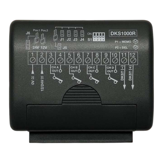
- Page 62 COLLEGAMENTO ELETTRICO - COLLEGAMENTO ELETTRICO - COLLEGAMENTO ELETTRICO COLLEGAMENTO ELETTRICO - COLLEGAMENTO ELETTRICO - ELEKTRISCHE AANSLUITING Pos.1 Pos.2 Legenda Légende Leyenda MEMO B1 - buzzer di segnalazione B1 - avertisseur sonore B1 - zumbador de señalización J1 - funzionamento uscita CH A J1 - fonctionnement sortie CH A J1 - funcionamiento en salida CH A CS1464A DC0561...
- Page 63 INSTALLAZIONE LETTORE TRANSPONDER DKSTPT - INSTALLING THE TRANSPONDER READER DKSTPT - INSTALLATION DU LECTEUR TRANSPONDEUR DKSTPT - INSTALLATION LESEGERÄT TRANSPONDER DKSTPT - INSTALACIÓN LECTOR TRANSPONDEDOR DKSTPT - INSTALLATIE VAN DE TRANSPONDERLEZER DKSTPT 90°...
- Page 64 INSTALLAZIONE TASTIERA CON LETTORE DKSDUALT - INSTALLING THE KEYPAD WITH TRANSPONDER READER DKSDUALT - INSTALLATION DU CLAVIER AVEC LECTEUR TRANSPONDEUR DKSDUALT - INSTALLATION DES CODESCHLOSSES MIT LESEGERÄT DKSDUALT - INSTALACIÓN DEL TECLADO CON LECTOR TRANSPONDEDOR DKSDUALT - INSTALLATIE VAN HET CODETABLEAU MET TRANSPONDERLEZER DKSDUALT 90°...
- Page 65 INSTALLAZIONE TASTIERA DKS250T-L - INSTALLING THE KEYPAD DKS250T-L - INSTALLATION DU CLAVIER DKS250T-L - INSTALLATION DES All rights reserved. Unauthorised copying or use of the information co CODESCHLOSSES DKS250T-L - INSTALACIÓN DEL TECLADO DKS250T-L - INSTALLATIE VAN HET CODETABLEAU DKS250T-L All rights reserved.
- Page 66 Il costruttore: CARDIN ELETTRONICA S.p.A. x x x x x x x x x x x x x x x x x x x x x x x x x x x x x x x x x x x x x x x x x x x x x x x x x x x x x x x x x x...
- Page 67 Notes:...
- Page 68 CARDIN ELETTRONICA S.P.A VIA DEL LAVORO, 73 – Z.I. CIMAVILLA - 31013 CODOGNÈ (TV) ITALY GPS 45.864, 12.375 TÉL: (+39) 04 38 40 40 11 FAX: (+39) 04 38 40 18 31 E-MAIL (ITALY) SALES.OFFICE.IT@CARDIN.IT E-MAIL (EUROPE) SALES.OFFICE@CARDIN.IT HTTP:// WWW.CARDIN.IT...