Table des Matières
Publicité
Les langues disponibles
Les langues disponibles
Liens rapides
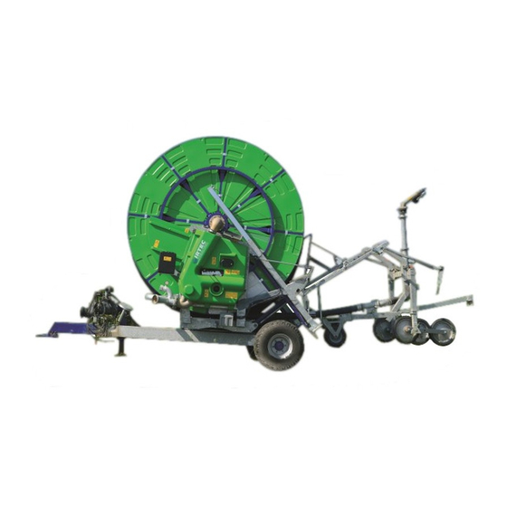
MOD. G/F8
I - MANUALE D'ISTRUZIONI USO E MANUTENZIONE ............pag. 1 ÷ 11
GB - INSTRUCTION MANUAL FOR USE AND MAINTENANCE.......pag. 12 ÷ 22
F - MANUEL D'INSTRUCTIONS POUR L'UTILISATION
ET L'ENTRETIEN..............................................................pag. 23 ÷ 33
D - BEDIENUNGS - UND WARTUNGSHINWEISE........................pag. 34 ÷ 44
E - MANUAL D'INSTRUCCION DE UTILIZO Y MANUTENCION...pag. 45 ÷ 55
MUF8G. 01
04.2007
Publicité
Chapitres
Table des Matières

Sommaire des Matières pour IRTEC G/F8
- Page 1 MOD. G/F8 I - MANUALE D’ISTRUZIONI USO E MANUTENZIONE …………pag. 1 ÷ 11 GB - INSTRUCTION MANUAL FOR USE AND MAINTENANCE…….pag. 12 ÷ 22 F - MANUEL D’INSTRUCTIONS POUR L’UTILISATION ET L’ENTRETIEN……………………………………………………..pag. 23 ÷ 33 D - BEDIENUNGS - UND WARTUNGSHINWEISE……………………pag. 34 ÷ 44 E - MANUAL D’INSTRUCCION DE UTILIZO Y MANUTENCION...pag.
- Page 2 41014 Castelvetro (Modena) Italy - Dichiara sotto la propria responsabilità che la macchina nuova descritta in appresso : irrigatrice su carro a naspo marca IRTEC - Declares on its own responsibility that the new machine hereby described ashose reel : irrigator trade-name IRTEC - Déclare sous sa propre responsabilité...
-
Page 3: Table Des Matières
INTRODUZIONE Grazie per avere scelto una macchina IRTEC, leggete attentamente le istruzioni riportate in questo manuale in modo da fami- liarizzare con la macchina, prima di cominciare il montaggio e l’utilizzo si raccomanda all’operatore di non effettuare opera- zioni azzardate e di usare in ogni occasione la prudenza necessaria. -
Page 4: Simboli Esposti Sulla Macchina E Loro
SIMBOLI ESPOSTI SULLA MACCHINA E LORO SIGNIFICATO 5) Questo simbolo indica il pericolo di A T T E N Z I O N E conducibilità elettrica Attenzione pericolo, non posizionare 1) Questo simbolo è utilizzato per indicare le mai il carrello porta irrigatore in prossi- operazioni e i punti pericolosi per l’incolumità... -
Page 5: Informazioni E Dati Tecnici
1. 0 INFORMAZIONI E DATI TECNICI 1.1 DIMENSIONI E PESO RUOTE 12,5 / 80 - 15,3 G/F8 inch RUOTE 10,0 / 75 - 15,3 G/F8 inch RUOTE LUNGHEZZA TUBO PESO VUOTA PESO CON ACQUA Ø I / D feet inch... -
Page 6: Trasporto,Consegna Della Macchina
1.2 TRASPORTO, CONSEGNA E MONTAGGIO DELLA MACCHINA Per motivi di ingombro in fase di trasporto la macchina può essere inviata con alcune parti smontate come le ruote o il tubo di entrata acqua. Il costruttore o chi per esso provvede al fissaggio della macchina con mezzi idonei rapportati alle masse caricate. -
Page 7: Dati Rumore Aereo
Montaggio del carrello portairrigatore 1) Montare i bracci porta ruote sul telaio centrale del carrello; 2) Montare le ruote facendo attenzione al serraggio delle viti; 3) Regolare l’altezza del carrello in modo che la slitta possa toccare uniformemente il terreno (fig.13 a) Per i carrelli equipaggiati con la 5 ruota registrare 1,5 Mt i bracci in modo che la base dell’irrigatore lavori... -
Page 8: Preparazione Della Macchina Alla Messa In Campo
2. 0 PREPARAZIONE DELLA MACCHINA ALLA MESSA IN CAMPO CONTROLLI DA EFFETTUARE Tabella lubrificanti 1) Controllare il livello dell’olio del riduttore. Se é necessario mettere Riduttore olio Sae 90 a livello con olio Sae 90. Supporti bobina grasso ISO MOV S2 2) Ingrassare la macchina in ogni sua parte. -
Page 9: Rientro Automatico Del Tubo
(fig.25) ESEMPIO DI INSERIMENTO MARCE IN BASE ALLA VELOCITA’ SCELTA: ATTENZIONE: per cambiare marcia è necessario MOD. G/F8 LEVA NR. 1 diminuire il numero di giri della turbina, agendo: da 10 a 15 m/h sull’apposita leva oppure da computer se la mac-... -
Page 10: Uso Della Macchina Con Computer (Opzional)
ATTENZIONE: se si mette in folle la macchina mentre il tubo é steso e in trazione, la bobina effettua un mezzo giro indietro violentemente. Assicurarsi quin- di che nessuna persona sia a contatto con la bobina durante questa operazione. 3) Se la macchina é equipaggiata di valvola di chiusura o di scarico, verificare che contemporaneamente al disinnesto automatico di fine corsa venga azionato anche il Fig.29 rubinetto a tre vie il quale a sua volta deve comandare la valvola di chiusura o di... -
Page 11: Avvolgimento Rapido Del Tubo
2.8 AVVOLGIMENTO RAPIDO DEL TUBO La presa di forza a cardano PTO posta sul riduttore serve ad avvolgere il tubo velocemente tramite trattore nel caso di imprevisti come pioggia. 1) Verificare che la leva nr.2 del riduttore sia in posizione di riavvolgimento tubo, altrimenti la PTO gira libera. 2) Collegare il cardano del trattore alla presa di forza del riduttore. -
Page 12: Rischi Residui
7.0 RISCHI RESIDUI La IRTEC in fase di progetto e costruzione ha verificato e quindi protetto le macchine nei punti ritenuti pericolosi per l’opera- tore, rimangono tuttavia alcuni rischi residui riscontrabili durante l’utilizzo della macchina. 1) Rischio di agganciamento e schiacciamento tra il montante della bobina e la bobina stessa quando questa é in rota- zione. -
Page 13: Cambio Della Postazione Della Macchina
8.2 CAMBIO DELLA POSTAZIONE DELLA MACCHINA Quando la macchina ha portato a termine il lavoro e la valvola è stata chiusa, la condotta rimane in pressione; per scollegare la macchina dalla condotta bisogna quindi seguire attentamente le istruzioni qui riportate: 1) Chiudere la valvola di adduzione della condotta che porta l’acqua alla macchina ;... -
Page 14: Introduction
INTRODUCTION Thank you for buying an IRTEC traveler. Please read this manual carefully before assembling and operating to get familiar with its many functions. Your safety is our first priority and failure to follow these instructions may cause serious injury or death. -
Page 15: Signs Present On The Machine And Their
SIGNS PRESENT ON THE MACHINE AND THEIR MEANING 5) This sign indicates a risk of electric power CAUTION danger. 1) This sign indicates the operations and parts Never position the rain gun trolley that may be risky for the safety of the operator. close to power lines or power packs. -
Page 16: Information And Technical Data
1. 0 INFORMATION AND TECHNICAL DATA 1.1 DIMENSIONS AND WEIGH WHEELS 12,5 / 80 - 15,3 G/F8 inch WHEELS 10,0 / 75 - 15,3 G/F8 inch WHEELS HOSE LENGHT WEIGHT EMPTY WEIGHT FULL OF WATER Ø I / D feet... -
Page 17: Transport Delivery And Assembly Of The
TRANSPORT, DELIVERY AND ASSEMBLY OF THE MACHINE Due to freight height and space limitations, some assembly may be required with your newly purchased micro traveler. Be sure to follow proper procedures when unloading and assembling the machine to avoid any danger or injury. Hooks are provided on the machine see (fig.6) to enable you to pick up the machine for unloading, assembly or repair. -
Page 18: Noise Level
Assembling the rain gun trolley 1) Assemble the wheel drop legs to the central beam of the trolley. 2) Assemble the wheels in the axle housings and tighten locking bolts. 3) Adjust the trolley height so that the frame is flat on the ground (fig.13 a). -
Page 19: Checking Machine Before Start-Up (Check List)
2. 0 CHECKING MACHINE BEFORE START UP (CHECK-LIST) Lubricant table INSPECTIONS TO BE CARRIED OUT Gearbox oil Sae 90 1) Check the oil level of the gearbox and if necessary add SAE 90. Reel supports grease ISO MOV S2 2) Grease the machine thoroughly (all grease fittings) and thereafter Greasers grease CH NFS 55 grease every 100 hours. -
Page 20: Automatic Hose Rewind
ESTIMATED SPEED PER GEAR SELECTION : MOD. G/F8 LEVER NR. 1 CAUTION: when changing gear make sure to decrease the speed of the turbine using the appropriate lever or by from 32.8 –... -
Page 21: Adjusting Of The Speed Equalizer
ATTENTION: when the machine is put in the idle position with the hose laid down, the reel makes a violent half turn backwards. Before carrying out this operation make sure that nobody is near the reel. 3) If the machine is fitted also with shut-off or discharge valve, check that both the automatic disengaging system at the end of the stroke and the 3-way valve which controls the opening and the shutting of the valves is activated. -
Page 22: Rapid Hose Retraction
2.8 RAPID HOSE RETRACTION The function of the P.T.O. power takeoff on the gearbox is to rewind the hose quickly by the tractor. In case of inconvenience such as rainfall etc., to rewind the hose by the P.T.O. proceed as follows: 1) Make sure that the gearbox lever no.2 is in “hose-rewind”... -
Page 23: Residual Risks
7.0 RESIDUAL RISKS Despite IRTEC taking all due precautions in the design and construction stages to eliminate any dangers to operators, some risks remain unavoidable in the operation of the machine. 1) HOOKING AND CRUSHING RISK between the support vertical rod of the reel and the reel itself when this is rotating. -
Page 24: Repositioning Of The Machine
8.2 REPOSITIONING OF THE MACHINE When the machine has stopped irrigating and the valve is closed, the pipe-work remains under pressure and in order to discon- nect the machine from the pipe-work proceed as follows. 1) Shut the hydrant supply valve off. 2) Open the breather valve manually. - Page 25 INTRODUCTION En vous remerciant d'avoir choisi une machine IRTEC, nous vous prions de lire attentivement les instructions reportées sur ce manuel afin de vous familiariser avec la machine avant de commencer le montage et l'utilisation. Il est conseillé à l'opérateur de ne pas effectuer d'opérations hasardées et d'agir en tous les cas avec la prudence nécessaire.
-
Page 26: Symboles Exposes Sur La Machine Et Leur
SYMBOLES EXPOSES SUR LA MACHINE ET LEUR EXPLICATION 5) Ce symbole indique le danger de conductibi- A T T E N T I O N lité électrique. Prêter donc une attention toute particulière 1) Ce symbole est utilisé pour indiquer les opé- et ne positionner jamais le chariot porte- rations et les points dangereux pour l'intégrité... -
Page 27: Dimensions Et Poids
1. 0 INFORMATIONS ET DONNEES TECHNIQUES 1.1 DIMENSIONS ET POIDS ROUES 12,5 / 80 - 15,3 G/F8 inch ROUES 10,0 / 75 - 15,3 G/F8 inch ROUES LANGUEUR DU TUYAU VIDE PLEINE D’ EAU Ø I / D inch feet... -
Page 28: Transport,Livraison De La Machine Et Montage.pag
1.2 TRANSPORT, LIVRAISON DE LA MACHINE ET MONTAGE Au moment du transport, pour diminuer l’encombrement, la machine pourrait être expédiée avec le chassis et certaines pièces démontées. Le constructeur ou la personne préposée, procédera à la fixation de la machine par des moyens appropriés rapportés aux masses chargées (fig.6). -
Page 29: Données Bruits Sonores
Montage du chariot porte-canon 1) Monter les bras porte-roues au corps central du chariot; 2) Monter les roues dans leur emplacement en fai- sant attention à serrer fortement les vis 3) Régler la hauteur du chariot de façon à ce que le patin touche uniformément le terrain (fig.13 a).Pour les chariots à... -
Page 30: Mise En Route De La Machine
2. 0 PREPARATION A AL MISE EN ROUTE DE LA MACHINE Tableau des lubrifiants CONTROLES A EFFECTUER 1) Contrôler le niveau de l'huile du réducteur et, si nécessaire, porter à Boîte de vitesse huile Sae 90 niveau avec de l'huile Sae 90 Supports bobine graisse ISO MOV S2 2) Graisser la machine dans toutes ses parties et ensuite graisser toutes... -
Page 31: Enroulement Automatique Du Tuyau
(fig.25) EXEMPLE D’INTRODUCTION DE LA VITESSE SUR LA BASE DE LA VITESSE CHOISIE : ATTENTION : il ne faut jamais changer MOD. G/F8 la vitesse LEVIER N° 1 sans avoir réduit la vitesse de rotation de la turbine an agis- da 10 a 15 m/h sant sur le levier correspondant ou par l’ordinateur si la ma-... -
Page 32: Utilisation De La Machine Si Équipée D'ordinateur
ATTENTION: si l'on met la machine au point mort avec le tuyau étendu et en traction, la bobine fera violemment un demi-tour en arrière. Avant d'effectuer cette opération, s'assurer qu'il n'y ait personne à côté de la bobine 3) Si la machine est équipée de vanne de fermeture ou de vanne de décharge, vérifier que le débrayage automatique à... -
Page 33: Enroulement Rapide Du Tuyau
2.8 ENROULEMENT RAPIDE DU TUYAU La prise de force à cardan placée sur le réducteur sert à enrouler rapidement le tuyau par l'intermédiaire du tracteur en cas d'imprévus, comme par exemple la pluie: 1) Vérifier que le levier n° 2 du réducteur soit en position d’enroulement tuyau, autrement la prise de force tournera libre 2) Brancher le cardan du tracteur à... -
Page 34: Risques Résiduels
7.0 RISQUES RESIDUELS Despite IRTEC taking all due precautions in the design and construction stages to eliminate any dangers to operators, some risks remain unavoidable in the operation of the machine. 1)Risque d'accrochage et d'écrasement entre le montant de la bobine et la bobine mê-me quand celle ci est en rotation. -
Page 35: Entretien De La Vanne De Fermeture
8.2 CHANGEMENT D'EMPLACEMENT A LA MACHINE Quand la machine a terminé le travail et la vanne a été fermée, la conduite demeure sous pression; pour débrancher la machine la machine de la conduite il faut suivre soigneusement les instructions suivantes: 1) Fermer la vanne d'adduction de la conduite qui amène l'eau à... - Page 36 VORWORT Wir danken Ihnen für das Vertrauen das Sie uns mit der Wahl einer Maschine IRTEC entgegengebracht haben. Diese Anwei- sungen bitte aufmerksam vor der Montage und der Verwendung lesen, um mit der Maschine vertraut zu werden. Empfehlun- gen: der Arbeiter darf keine gefährliche Arbeit ausführen, muß vorsichtig handeln und aufmerksam den Gebrauchsanweisun- gen folgen.
-
Page 37: Auf Der Maschine Angebrachte Symbole Und
AUF DER MASCHINE ANGEBRACHTE SYMBOLE UND IHRE BEDEUTUNG 5) Dieses Symbol weist auf elektrische A C H T U N G Leitfähigkeit hin. ! Achtung Gefahr. Den 1)Dieses Symbol weist auf Vorgänge und Regnerwagen niemals in der Nähe von Elektro- Punkte hin, die für den Bediener gefährlich leitungenoder Kabinen aufstellen und darauf werden können. -
Page 38: Himweise Und Technische Daten
1. 0 HIMWEISE UND TECHNISCHE 1.1 DIMENSIONEN UND GEWICHT 2 RÄDERN 12,5 / 80 - 15,3 G/F8 inch RÄDERN 10,0 / 75 - 15,3 G/F8 inch RÄDERN LEERGEWICHT GEWICHT MIT WASSER SCHLAUCHLÄNGE Ø I / D inch feet 1969 5003... -
Page 39: Transport Lieferung Und Montage Der Maschine
1.2 TRANSPORT, LIEFERUNG UND MONTAGE DER MASCHINE Aus Raumbedarfgründen kann die Maschine mit demontiertem Gestell und anderer Teile geliefert werden. Der Bauer oder Veran-wortliche führt das Zu- sammenmontieren der Maschine mit geeigneten Mitteln entspre-chend den geladenen Teilen durch (Siehe tabelle). Zur Entladung und Montage die Ma- schine an den bestimmten Punkten, wie im (Abb.6), einhaken. -
Page 40: Daten Über Geräuschprgrl
Montage des Beregnungswagens 1) Die Radarme zum Wagenmittelstamm montieren. 2) Die Räder auf das spezielle Gehäuse montieren und die Schrauben stark anziehen. 3) Die Wagenhöhe einstellen, so daß der Schlitten flach am Boden liegt (Abb.13 a). Für 5 -Räder Wagen die Arme einstellen, so daß der Regner horizontal arbeitet (Abb.13 b). -
Page 41: Inbetriebnahme Der Maschine
2. 0 INBETRIEBNAHME DER MASCHINE Schmiermitteltabelle KONTROLLE 1) Ölstand im Getriebe kontrollieren, wenn notwendig mit Sae 90 na- Getriebe öl Sae 90 chfüllen. Rollenlager Schmierfett ISO MOV S2 2) Alle Teile der Maschine abschmieren und später alle 100 Stunden Schmiernippel Schmierfett CH NFS 55 abschmieren. -
Page 42: Automatischer Schlaucheinzug
Position fixiert werden (Abb.25) BEISPIEL FÜR GANGEINSCHALTUNG DER ARBEITSGESCHWINDIGKEIT : ACHTUNG: Zum Umschalten muss die Drehzahl der Turbine MOD. G/F8 HEBEL NR. 1 gemindert werden, dazu den entsprechenden Hebel betätigen von 10 “ 15 m/St. -
Page 43: Verwendung Des Kompressor (Zubehör)
VORSICHT: wenn die Maschine mit aufgerollten und gezogenen Schlauch auf Leerlauf geschaltet wird, macht die Schlauchrolle eine halbe heftige Drehung rückwärts. Bevor diese Operation ausgeübt wird, sich vergewissern, daß niemand in der Nähe der Schlauchrolle ist 3) Wenn die Maschine mit Sperr- oder A-blassventil für Wasser ausgestattet ist, Abb.29 kontrollieren Sie, daß... -
Page 44: Schnelle Schlauchaufrollung
2.8 SCHNELLE SCHLAUCHAUFROLLUNG Wenn notwendig (z.B. beim schlechtem Wetter) den Schlauch durch die Zapfwelle seitlich der Maschine schnell aufziehen. 1) Überprüfen, dass der Hebel Nr.2 des Getriebes sich in der Position für die Schlauchaufwicklung befindet, andernfalls dreht die PTO frei. 2) Kardanwelle vom Traktor am Nebenantrieb des Getriebes anschließen. -
Page 45: Weitere Gefahren
7.0 WEITERE GEFAHREN In der Planungs- und Bauphase hat IRTEC die Maschine in den gefährlichsten Punkten für den Arbeiter kontrolliert und ge- schützt. Jedoch bleiben einige Gefahren bei der Anwendung der Maschine. 1) Gefahr von Einhaken und Quetschungen zwischen dem Schlauchrollengestell und derselben Schlauchrolle, wenn diese sich dreht. -
Page 46: Stellungwechsel Der Maschine Und Ventilöfenung
8.2 STELLUNGWECHSEL DER MASCHINE UND VENTILöFFNUNG Wenn die Maschine die Arbeitphase beendet hat, und das Ventil geschlossen hat, bleibt die Leitung unter Druck, deshalb ist es notwendig die folgenden Hinweise zu folgen. 1)Das Leitungszuführventil, das Wasser zur Maschine bringt, schließen. 2)Den neben dem Ventil befindliche Entlüftungshahn Manuell öffnen, 3) Die Ventilklappe durch Ziehen des speziellen Handgriffsmanuell öffnen,um die Maschine zu entlüften. - Page 47 INTRODUCCION Gracias por haber escogido una maquina IRTEC. Por favor lea atentamente las instrucciones descritas en este manual para conocer y familiarizarse con la máquina antes de empezar a montarla y utlizarla. Se recomienda al montador no efecturar ope- raciones peligrosas y utilizar en cada ocasión la prudencia necesaria.
-
Page 48: Mandos De La Maquina
SIMBOLOS EN LA MAQUINA Y SU SIGNIFICADO 5) Este simbolo indica riesgo electrico. A T E N C I O N Nunca poner el cañon cerca de cualquier 1) Este simbolo indica las operaciones y partes fuente de energia. Asegurese que el agua del que pueden causar riesgo en la seguridad del aspersor no esta en contacto con ninguna fuen- operador. -
Page 49: Informacion Y Datos Tecnicos
1. 0 INFORMACION Y DATOS TECNICOS 1.1 DIMENSIONES Y PESO RUEDAS 12,5 / 80 - 15,3 G/F8 inch RUEDAS 10,0 / 75 - 15,3 G/F8 inch RUEDAS LARGO DE LA MANGUERA PESO SIN AGUA PESO CON AGUA Ø I / D... - Page 50 1.2 TRANSPORTE, ENTREGA Y MONTAJE DE LA MAQUINA Debido a las dimensiones y peso de la maquina, esta puede ser enviada con algunas partes desmontadas, por ejemplo ruedas y tubo de entrada del agua. Es por eso que la maquina tiene unos puntos para engancharla y manipularla, tan- to en la descarga como en el montaje, con los medios idoneos al volumen de la maquina.
-
Page 51: Nivel De Ruidos
Montaje del carro portaaspersor 1) Montar los brazos de las ruedas del bastidor cen- tral. 2) Montar las ruedas teniendo precaucion al apretar los tornillos. 3) Regular la altura del carro de manera que la pla- taforma toque uniformemente el terreno (fig 13 a). Para los carros equipados con 5 ruedas, controlar la 1,5 Mt altura de los brazos de manera que la base del asper-... - Page 52 2. 0 PREPARACIÓN DE LA MÁQUINA PARA SU FUNCIONAMIENTO EN EL CAMPO CONTROLES A EFECTUAR Tabla de lubricantes Reductor aceite Sae 90 1) Controlar el nivel de aceite del reductor y, si es necesario, agregar Soporte de la bobina grasa ISO MOV S2 aceite Sae 90 hasta el nivel .
-
Page 53: Parada Automatica De La Maquina
(fig.25) ESEMPIO DI INSERIMENTO MARCE IN BASE ALLA VELOCITA’ SCELTA: ATENCIÓN: para cambiar la marcha es necesario disminuir MOD. G/F8 LEVA NR. 1 el número de revoluciones de la turbina, operando en la espe- da 10 a 15 m/h cífica leva o, si la máquina está... - Page 54 ATENCIÓN: Si se pone la máquina en punto muerto 0 con el tubo extendido y en tracción, la bobina efectuará violentamente medio giro. Asegúrese de que durante esta operación ninguna persona se encuentre manipulando la bobina 3)Si la máquina está equipada de válvula de cierre o de descarga de agua, verifique que en el momento de funcionamiento automático de fin de carrera, la llave a tres Fig.29 pistas que pilota el cierre y la abertura de las válvulas esté...
-
Page 55: Uso Nocturno De La Maquina
2.8 ENROLLAMIENTO RÁPIDO DEL TUBO La toma de fuerza a cardan está sobre el redu-ctor para el enrollamiento rápido del tubo, por mediación del tractor en caso de imprevisto, como por ejemplo la lluvia. 1) Controlar que la leva nº 2 del reductor esté en posición de rebobinado tubo, sino la PTO gira libre. 2) Empalmar el cardan a la toma de fuerza del reductor. -
Page 56: Riesgos Por Los Residuos
7.0 RIESGOS POR LOS RESIDUOS En la fase de proyecto y construcción IRTEC se ocupa del control y la protección de la má-quina en los posibles peligros para el opera-dor, sin embargo, algunos riesgos residuales pueden existir todavía en el momento de la utilización de la máquina. -
Page 57: Manutención De La Valvula De Cierre
8.2 CAMBIO DE LA POSICIÓN DE LA MÁQUINA Cuando la máquina ha terminado el trabajo y la válvula está cerrada, baje la presión en los conductos; seguir las instrucciones siguientes: 1) Cerrar la válvula de alimentación del con-ducto que porta el agua a la máquina. 2) Abrir manualmente la llave de escape situada en la parte superior de la válvula. - Page 58 Via G. Mameli, 12/14 - 41014 Castelvetro ( MO ) - Italy Tel. + 39 059 79 05 00 FAX + 39 059 79 07 46 Email: info@irtec-irrigation.com Http://www.irtec-irrigation.com...