Table des Matières
Publicité
Les langues disponibles
Les langues disponibles
Liens rapides
Publicité
Chapitres
Table des Matières

Manuels Connexes pour Honeywell Home AQ1000TN2


Sommaire des Matières pour Honeywell Home AQ1000TN2
- Page 1 Hydronic Zoning Thermostat AQ1000TN2 OWNER’S GUIDE 69-2005EF-02 M38489...
- Page 2 Need Help? For assistance with this product please visit resideo.com or call Customer Care toll-free at 1-800-468-1502. Read and save these instructions. The product should not be disposed of with other household waste. Check for the nearest authorized collection centers or authorized recyclers. The correct disposal of end-of-life equipment will help prevent potential negative consequences for the environment and human health.
-
Page 3: Table Des Matières
TABLE OF CONTENTS User’s Section About your new thermostat ..................... Screen display ........................Power-up / modes of operation ..................User’s Configuration Menu ..................... Temperature Display and Setting ................. Installer’s section Installation ..........................10 Configuration switches ..................... 11 Appendix Technical Specifications ....................15 2-year limited warranty ..................... -
Page 4: About Your New Thermostat
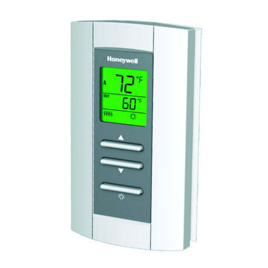
ABOUT YOUR NEW THERMOSTAT Resideo’s AQ1000TN2 hydronic zoning thermostat can be used to control the ambient air temperature or floor temperature. You can choose among the following temperature control modes (see page 11): Screen A mode: • controls and displays the... -
Page 5: Screen Display
SCREEN DISPLAY The arrow appears when the setpoint is displayed Indoor temperature Temperature control mode Outdoor temperature Heating is On Keypad lock M38491 Freeze Protection mode Comfort / Unoccupied (see next page) mode (see next page) The outdoor temperature will be displayed only if the data is available. This icon appears to indicate that the thermostat settings cannot be modified as the hydronic zoning controller has locked the keypad. -
Page 6: Power-Up / Modes Of Operation
POWER-UP / MODES OF OPERATION The thermostat is powered through the wires connecting it to the AQ2000 Series hydronic zoning controller. Therefore, the thermostat turns on when the controller is powered. The thermostat can be placed in one of the 3 following modes of operation: Comfort Mode The thermostat is normally in the Comfort mode. -
Page 7: User's Configuration Menu
USER’S CONFIGURATION MENU 1. Press the backlight button for 3 seconds to access the configuration menu. The first parameter is displayed. 2. To modify a parameter, press either of the ▲▼ buttons. 3. To display the next parameter, briefly press the backlight button. - Page 8 Display Format Use this parameter to choose the temperature display mode. When the automatic mode is selected, the thermostat displays the temperature format set on the hydronic zoning controller. If °F or °C is selected, the thermostat displays the temperature in the selected format respectively.
-
Page 9: Temperature Display And Setting
TEMPERATURE DISPLAY AND SETTING The thermostat generally displays the actual (measured) temperature. To display the setpoint temperature, press one of the ▲▼ buttons once. The setpoint will be displayed for the next 5 seconds. An arrow appears at the left of the setpoint temperature display. -
Page 10: Installation
INSTALLATION 1. Remove the faceplate from the base by unscrewing the screw underneath the thermostat and tilting the bottom of the faceplate up. Note that the screw remains captive on the base. 2. Insert the wires through the center hole of the base and secure the base to the wall or onto an electrical box. -
Page 11: Configuration Switches
CONFIGURATION SWITCHES The configuration (DIP) switches are located behind the thermostat faceplate. NOTE: DIP switch 1 is not used. INSTALLER CONFIGURATION MENU (SWITCH 2) USER Use DIP switch 2 to set the thermostat in either Installer or User mode. INST. TEMPERATURE CONTROL MODE (SWITCHES 3 &... - Page 12 INSTALLER’S CONFIGURATION MENU The parameters in the installer’s configuration menu must be modified by qualified personnel only. Incorrect settings can result in property damages. Remove the thermostat from its base. Place switch 2 on the back of the thermostat in the up position (Installer mode). Return the thermostat to its base.
- Page 13 Minimum Setpoint Temperature This parameter is the minimum temperature at which the thermostat can be set. Maximum Setpoint Temperature This parameter is the maximum temperature at which the thermostat can be set. Freeze Protection Temperature This parameter is used to prevent frozen pipes inside the room where the thermostat is located.
- Page 14 Minimum Floor Limit Temperature This parameter is used only if the thermostat has been configured for AF temperature control. If the floor temperature is below that limit, the pump or valve will be activated regardless of the ambient temperature. Maximum Floor Limit Temperature This parameter is used only if the thermostat has been configured for AF temperature control.
-
Page 15: Technical Specifications
TECHNICAL SPECIFICATIONS Power supply: powered by the boiler controller Default setpoint range: 40 °F to 100 °F (5 °C to 38 °C) Default floor limit (AF model): 40 °F to 100 °F (5 °C to 38 °C) Setpoint interval: ± 1.0 °F (0.5 °C) Indoor temperature display range: 32 °F to 158 °F (0 °C to 70 °C) Outdoor temperature display range: -58 °F to 212 °F (-50 °C to 100 °C) Display resolution: ±... -
Page 16: 2-Year Limited Warranty
2-YEAR LIMITED WARRANTY Resideo warrants this product, excluding battery, to be free from defects in workmanship or materials, under normal use and service, for a period of two (2) years from the date of first purchase by the original purchaser. If at any time during the warranty period the product is determined to be defective due to workmanship or materials, Resideo shall repair or replace it (at Resideo's option). - Page 17 Resideo's sole responsibility shall be to repair or replace the product within the terms stated above. RESIDEO SHALL NOT BE LIABLE FOR ANY LOSS OR DAMAGE OF ANY KIND, INCLUDING ANY INCIDENTAL OR CONSEQUENTIAL DAMAGES RESULTING, DIRECTLY OR INDIRECTLY, FROM ANY BREACH OF ANY WARRANTY, EXPRESS OR IMPLIED, OR ANY OTHER FAILURE OF THIS PRODUCT.
- Page 18 69-2005EF—02 M.S. Rev. 09-20 | Printed in United States © 2020 Resideo Technologies, Inc. All rights reserved. The Honeywell Home trademark is used under license from Honeywell International, Inc. This product is manufactured by Resideo Technologies, Inc. and its affiliates.
- Page 19 Thermostat de zonage hydronique AQ1000TN2 GUIDE DE L’UTILISATEUR 69-2005EF-02 M38489...
- Page 20 Besoin d’aide? Pour obtenir de l’aide sur ce produit, veuillez consulter le resideo.com ou joindre le service à la clientèle en composant sans frais le 1 800 468-1502. Veuillez lire le mode d’emploi et le conserver en lieu sûr. Ce produit ne doit pas être jeté avec les autres ordures ménagères. Trouvez le centre de collecte ou de recyclage autorisé...
- Page 21 TABLE DES MATIÈRES Section de l’utilisateur À propos du thermostat ....................Affichage ..........................Mise sous tension / modes de fonctionnement ............. Menu de configuration de l’utilisateur ............... Affichage et réglage de la température ..............Section de l’installateur Installation ..........................10 Commutateurs de configuration ...................
-
Page 22: À Propos Du Thermostat
À PROPOS DU THERMOSTAT Le thermostat de zonage hydronique AQ1000TN2 de Resideo permettent de réguler la température ambiante ou la température du plancher. Vous pouvez choisir l’un des modes de régulation de la température suivants (voir la page 11) : Écran... -
Page 23: Affichage
AFFICHAGE La flèche apparaît lorsque la température de consigne est affichée Température intérieure Mode de régulation de la température Température extérieure Chauffage en cours Clavier verrouillé Mode Confort / M38491 Mode Hors-gel (voir la Inoccupé (voir la page page suivante) suivante) La température extérieure sera affichée uniquement si les données sont disponibles. -
Page 24: Mise Sous Tension / Modes De Fonctionnement
MISE SOUS TENSION / MODES DE FONCTIONNEMENT Le thermostat est alimenté au moyen des fils qui le relient au régulateur hydronique de zonage Série AQ2000. Le thermostat est donc mis sous tension en même temps que le régulateur. On peut placer le thermostat dans l’un des modes de fonctionnement suivants : Mode Confort Le thermostat est normalement en mode Confort. -
Page 25: Menu De Configuration De L'utilisateur
MENU DE CONFIGURATION DE L’UTILISATEUR 1. Appuyer sur le bouton de rétroéclairage pendant 3 secondes pour accéder au menu de configuration. Le premier paramètre apparaît. 2. Pour modifier un paramètre, appuyer sur l’un des boutons ▲▼. 3. Pour afficher un autre paramètre, appuyer brièvement sur le bouton de rétroéclairage 4. - Page 26 Format d’affichage Ce paramètre permet de choisir le format d’affichage de la température. Si vous choisissez le mode automatique (Au), le thermostat affichera la température dans le format utilisé par le régulateur hydronique de zonage. Si vous choisissez le mode °F ou °C, le thermostat affichera respectivement la température en °F ou °C.
-
Page 27: Affichage Et Réglage De La Température
AFFICHAGE ET RÉGLAGE DE LA TEMPÉRATURE Le thermostat affiche généralement la température réelle (mesurée). Pour afficher la température de consigne, appuyer une fois sur l’un des boutons ▲▼. La température de consigne sera affichée pendant les 5 secondes suivantes. Une flèche apparaît à gauche de la température de consigne affichée. Pour changer la température de consigne, appuyer sur un des boutons ▲▼... -
Page 28: Installation
INSTALLATION 1. Retirer la façade du socle en desserrant la vis située sous le thermostat et en tirant sur la partie inférieure. Noter que la vis reste captive sur le socle. 2. Insérer les fils à travers l’ouverture du centre du socle et fixer le socle sur le mur ou sur une boîte électrique. -
Page 29: Commutateurs De Configuration
COMMUTATEURS DE CONFIGURATION Les commutateurs de configuration (DIP switch) sont situés au dos de la façade du thermostat. REMARQUE : Le commutateur 1 n’est pas utilisé. USER MENU DE CONFIGURATION DE L’INSTALLATEUR (COMMUTATEUR 2) INST. Utiliser le commutateur 2 pour mettre le thermostat en mode Installateur ou Utilisateur. - Page 30 MENU DE CONFIGURATION DE L’INSTALLATEUR Seuls des installateurs compétents sont autorisés de modifier les paramètres du menu de configuration. Des réglages inappropriés peuvent causer des dommages à la propriété. Retirer le thermostat du socle. Positionner le commutateur 2, au dos du thermostat, vers le haut (mode Installateur). Remettre le thermostat sur son socle.
- Page 31 Température de consigne minimale Ce paramètre est la température minimale à laquelle le thermostat peut être réglé. Température de consigne maximale Ce paramètre est la température maximale à laquelle le thermostat peut être réglé. Température Hors-gel Ce paramètre sert à empêcher le gel dans les tuyaux dans la pièce où...
- Page 32 Limite de température minimale du plancher Ce paramètre servira uniquement si le thermostat est configuré en mode AF. Si la température du plancher est inférieure à cette limite, la pompe ou valve sera activée peu importe la température ambiante. Limite de température maximale du plancher Ce paramètre servira uniquement si le thermostat est configuré...
-
Page 33: Fiche Technique
FICHE TECHNIQUE Alimentation : Alimenté par le régulateur hydronique de zonage Plage de réglage par défaut : 5 °C à 38 °C (40 °F à 100 °F) Limite du plancher par défaut (modèle AF) : 5 °C à 38 °C (40 °F à 100 °F) Intervalle de consigne : ±... -
Page 34: Garantie Limitée De 2 Ans
GARANTIE LIMITÉE DE 2 ANS Resideo garantit ce produit, à l'exception des piles, contre tout défaut de pièce ou de main-d'oeuvre, durant une période pour cinq (5) ans à partir de la date d'achat par le consommateur d'origine si le produit est utilisé et entretenu convenablement. En cas de défaillance ou de mauvais fonctionnement pendant la période de garantie, Resideo remplacera ou réparera le produit, à... - Page 35 VIOLATION QUELCONQUE D'UNE GARANTIE, EXPRESSE OU TACITE, APPLICABLE AU PRÉSENT PRODUIT, OU TOUTE AUTRE DÉFAILLANCE DU PRÉSENT PRODUIT. Certaines provinces ne permettent pas l'exclusion ou la restriction des dommages indirects ou accessoires et, par conséquent, la présente restriction peut ne pas s'appliquer. CETTE GARANTIE EST LA SEULE GARANTIE EXPRESSE FAITE PAR RESIDEO POUR CE PRODUIT.
- Page 36 69-2005EF—02 M.S. Rev. 09-20 | Imprimé aux États-Unis www.resideo.com © 2020 Resideo Technologies, Inc. All rights reserved. The Honeywell Home trademark is used under license from Honeywell International, Inc. This product is manufactured by Resideo Technologies, Inc. and its affiliates.