Télécharger Imprimer la page

Publicité

Les langues disponibles

Les langues disponibles

Liens rapides

VUpoint Bullet Outdoor
IP Camera
Model: RVCM52E
Installation Guide
1

Publicité

loading

Sommaire des Matières pour RISCO Group RVCM52E

  • Page 1 VUpoint Bullet Outdoor IP Camera Model: RVCM52E Installation Guide...
  • Page 2 Safety Precautions These instructions are intended to ensure that the user can use the product correctly to avoid danger or property loss. WARNINGS: Installation or usage of this product that is not in accordance with the intended use as defined by the supplier and as described in the instructional materials can result in damage, injury, or death.
  • Page 3 Introduction RISCO Group presents VUpoint, a revolutionary live video verification solution which seamlessly integrates IP Cameras within RISCO’s professional security systems. Powered by the RISCO Cloud (RISCO Application Server), VUpoint provides an unprecedented level of security and live video monitoring capabilities to monitoring stations and end-users alike.
  • Page 4 IP Camera Components and Dimensions Figure 1 IP Camera Components Label Port Name Function Connector Description Network port Ethernet Connects to standard Ethernet port cable DC12V rt Power input port Power Input DC 12V power port Figure 2 IP Camera Dimensions...
  • Page 5 IP Camera Mounting and Installation After reading the installation instructions and before installing your IP camera, prepare a plan for mounting the IP camera at your protected site. Correct placement of your IP camera is crucial for optimal security-monitoring performance. First, determine which areas need to be protected and then map out the most optimal areas for installing your IP camera.
  • Page 6 Step Description Place the installation positioning template on the installation surface such as ceiling or wall. Make holes in the installation surface according to the installation positioning template. Insert the expansion bolts from the accessories bag into the holes you just made. Position the IP camera base over the holes Use the screws from the accessories bag to secure the IP camera firmly.
  • Page 7 Powering-up the IP Camera Connect the camera power adapter to an electrical outlet. Connecting the IP Camera to the Network The IP camera supports a LAN network connection. Connecting to a LAN Network Connecting the IP camera to a network using the LAN (Local Area Network) enables easy connection and setup with compatible APs (Access Points), e.g.
  • Page 8 IP Cameras and the RISCO Cloud Installer Application The RISCO Cloud Installer Application provides an interface to your control panel from a local or remote PC via the Web. This enables you to add IP cameras and define camera and event alarm trigger settings. IMPORTANT –...
  • Page 9 Figure 6 Control Panel Update Page 4. Click the Network Cameras link in the left-hand column; the IP Camera List page is displayed. Figure 7 IP Cameras List 5. Click Add Camera; the Add Camera dialog box is displayed. Figure 8 Add Camera 6.
  • Page 10 7. Click Add. If an “unable to configure Internet Access”, “UPnP Client Error” or similar message is displayed, refer to the Troubleshooting section. 8. Once the “camera is ready for use” message is displayed, click OK. The defined IP camera is displayed in the IP Cameras page. Figure 9 IP Camera List NOTE –...
  • Page 11 To define camera trigger settings: 1. From the Control Panel Cameras page, click the Triggers tab, the Camera Triggers List page is displayed. Figure 10 Camera Triggers List 2. Click Add Trigger; the Add Triggers dialog box appears. Figure 11 Add Trigger 3.
  • Page 12 Additional fields are displayed in the Add Trigger dialog box according to the event type that you selected (see examples below for Partition and Detector event types). Figure 12 Add Partition Event Trigger Figure 13 Add Detector Event Trigger 4. Define the following fields in the Add Trigger dialog box according to the event type that you selected.
  • Page 13 6. Once finished, click Done. The defined camera trigger is displayed in the Camera Triggers List page. Figure 14 Camera Triggers List NOTE – You also have the options to edit , create a duplicate , or to delete the selected camera trigger. IMPORTANT –...
  • Page 14 Troubleshooting Internet Configuration/UPnP Client Error Not all routers support UPnP and in some routers UPnP is disabled by default. If you have tried configuring internet access automatically and get the message “unable to configure Internet Access”, “UPnP Client Error” or similar, it should possible to set your IP cameras and router up manually.
  • Page 15 2. Once the Camera Interface Login page is displayed, enter the User and Password into the relevant fields and click Login. NOTE: By Default the User and Password for camera login is “admin” and “_AdmiN_+ camera MAC address” (e.g. _AdmiN_AABBCCDDEEFF). 3.
  • Page 16 NOTE: By default the TCP/IP settings should already be defined. 7. Click Save to save the changes. 8. Select Connection. The Connection Parameters page is displayed. Figure 18 Connection Parameters 9. Set the following port connection parameters of the camera: TCP Port Set the TCP port you want to define for the camera (in our example 47777).
  • Page 17 Step 3: Router Port Forwarding Settings By default, the security features on many routers prevent access to the devices on your home/business network from the Internet. To open a port, you need to enable “port forwarding” on your router. Router administration screens can vary, but typically, you would do the following to open a port: 1.
  • Page 18 3. For the first camera enter the settings as shown in the screenshot below. Remember to use the same local IP address and external port numbers as was set in the camera settings in Step 2. Figure 20 Port Forwarding page (populated) NOTE: For HTTP, RTSP and HTTPs Port settings use the TCP Protocol option.
  • Page 19 Product Specification Parameter Main Processor TI Davinci high performance DSP Embedded LINUX Support real-time network monitor, local record, and remote operation at the System Resources same time. User Interface Remote operation interface such as WEB, DSS, PSS. System Status Bit stream statistics, log, and software version. Image Sensor 1/3-inch CMOS Pixel...
  • Page 20 DC 12V Power DC 12V Power 5 W MAX Consumption Working -20℃~+60℃ Temperature ≤95% Working Humidify 70*66*160 Dimensions(mm) 500g(Excluding box) Weight Bracket installation Installation...
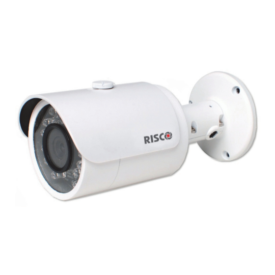
  • Page 21 VUpoint Caméra IP Extérieure Bullet Modèle: RVCM52E Guide d’Installation...
  • Page 22 Précautions d’Usage Ces instructions sont destinées à faire en sorte que l'utilisateur puisse utiliser le produit correctement pour éviter le danger ou la perte matérielle. MISES EN GARDE: L’installation ou l'utilisation de ce produit sans respecter l'usage prévu tel que défini par le fournisseur et comme décrit dans les matériels pédagogiques peut entraîner des dommages, des blessures ou la mort.
  • Page 23 Introduction RISCO Group présente VuPoint, une solution de vérification de la vidéo en direct révolutionnaire qui intègre de façon transparente les caméras IP au sein de nos systèmes de sécurité professionnels. Géré par RISCO Cloud, VuPoint offre un niveau de sécurité sans précédent en offrant la surveillance vidéo en direct aux stations de télésurveillance et aux utilisateurs commerciaux/résidentiels.
  • Page 24 Composants Caméra IP et Dimensions Figure 1 Composants Caméra IP Indice Nom Port Fonction Connecteur Description Port réseau Port Connecté à un câble Ethernet Ethernet standard DC12V rt Port Entrée Alim. Port Alim. Entrée Alim. 12V DC Figure 2 IP Dimensions Caméra...
  • Page 25 Montage et installation Caméra IP Après avoir lu les instructions d'installation et avant d'installer votre caméra IP, préparer un plan de montage de la caméra IP correspondant au site à protéger. L’emplacement correct de votre caméra IP est crucial pour une performance optimale de surveillance et de sécurité.
  • Page 26 IMPORTANT- S'il vous plaît assurez-vous que la surface de montage peut supporter au moins 3 fois le poids de la caméra et de son support. Etape Description Placer le gabarit de positionnement d’installation sur la surface d'installation tel que plafond ou mur. Faire des trous dans la surface d'installation selon le gabarit de positionnement d’installation.
  • Page 27 Mise sous tension de la caméra IP Branchez l'adaptateur d'alimentation de la caméra à une prise électrique. Connexion de la Caméra IP au Réseau La caméra IP prend en charge une connexion réseau LAN. Connexion au réseau local Le raccordement de la caméra IP à un réseau en utilisant le LAN (Local Area Network) permet la connexion et les réglages avec les points d'accès compatibles, par exemple passerelle ou du routeur.
  • Page 28 Caméras IP et Application Installateur RISCO Cloud L’application Installateur RISCO Cloud fournit une interface pour contrôler votre centrale à partir d'un PC local ou à distance via le Web. Cela vous permet d'ajouter des caméras IP et de définir la caméra et les paramètres des événements d'alarme de déclenchement.
  • Page 29 Figure 6 Page Centrale Mise à jour 4. Cliquez sur le lien caméras réseau dans la colonne de gauche, la page de la liste des caméras IP s’affiche. Figure 7 Liste Caméras IP 5. Cliquez sur Ajouter caméra, la boîte de dialogue d'ajout de caméra s'affiche. Figure 8 Ajout Caméra 6.
  • Page 30 Champ Description Adresse MAC Entrez l'adresse MAC comme indiqué sur la boîte ou sur la couverture arrière de la caméra IP. L'adresse MAC (media access control address) est l'identifiant unique attribué à la caméra IP pour les communications sur le réseau physique. NOTE: L'adresse MAC est sensible à...
  • Page 31 Définition des paramètres de déclenchement de la caméra Tout événement dans la liste suivante peut être défini pour déclencher une alarme. Evènements Partition Alarme Incendie Alarme Panique Alarme Médical Alarme Armement Total Armement Partiel Désarmement Agression Sabotage Alarme 24 HR-X Alarme Inondation Alarme Gaz Alarme Environ.
  • Page 32 3. Définir les champs suivants dans la boîte de dialogue d'ajout de déclencheur: Champ Description Type d’événements Etiquette Entrez un nom pour le déclencheur Evénements Partition et de caméra Détecteur Caméra Choisir une caméra dans la liste Evénements Partition et Détecteur Type Evénement Choisissez un type d’événements...
  • Page 33 5. Définir les définitions suivantes pour l'image (fixe) et le clip (vidéo): Champ Description Images Durée de préalarme (sec) – temps, avant l'événement réel survenu, pour (fixes) commencer à afficher des images fixes. Nombre d’images – nombre d'images fixes à afficher. Intervalle entre images (sec) –...
  • Page 34 Dépannage Configuration Internet / Erreur Client UPnP Tous les routeurs ne supportent pas l'UPnP et pour certains routeurs l’UPnP est désactivé par défaut. Si vous avez essayé de configurer l'accès automatique à Internet et reçu un message "Impossible de configurer l'accès Internet", "Erreur Client UPnP"...
  • Page 35 1. Saisissez l'adresse IP et le port Web de la caméra, par exemple 192.168.010.168:37080 (le port Web par défaut est 37080). NOTE – Lorsque vous utilisez plusieurs caméras, le port Web par défaut ne doit pas être le même. 2. Une fois que la page d'interface de connexion de la caméra s'affiche, entrez les noms d’utilisateur et mot de passe dans les champs appropriés et cliquez sur Connexion.
  • Page 36 1. Sélectionnez l'option de mode ‘Static’ et entrez l'adresse IP statique que vous souhaitez définir pour la caméra (dans notre exemple 192.168.1.122). Définir également le masque de sous-réseau et l'adresse de la passerelle par défaut (dans notre exemple 255.255.255.0 et 192.168.1.1).
  • Page 37 Etape 3: Configuration de la redirection des ports du Routeur Par défaut, les fonctions de sécurité sur de nombreux routeurs empêchent l'accès à Internet aux périphériques de votre réseau domestique/d'entreprise. Pour ouvrir un port, vous devez activer la "redirection de port" sur votre routeur. Les écrans d'administration du routeur peuvent différer, mais en général, vous devez procéder comme suit pour ouvrir un port: 1.
  • Page 38 4. Cliquez sur Appliquer/Enregistrer les paramètres pour enregistrer les modifications. 5. Redémarrez la caméra en débranchant et en rebranchant son alimentation. 6. Répétez les étapes précédentes pour chaque caméra en utilisant l’adresse IP locale et les numéros de port externes précédemment défini dans les paramètres de la caméra.
  • Page 39 Spécifications Produit Paramètres Processeur principal TI Davinci DSP haute performance LINUX embarqué Support visualisation réseau en temps réel, enregistrement local, et exploitation Ressources Système distante simultanés. Interface Utilisateur Interface de gestion à distance tels que WEB, DSS, PSS. Etat Système Statistiques de débits, historique, et version du logiciel.
  • Page 40 Paramètres Alimentation DC 12V Avertissement! Ne pas relier les deux sources d'énergie pour alimenter l'appareil en même temps, cela peut causer des dommages à l'appareil ! Consommation 5W MAX Température de -20℃~+°~+60℃ fonctionnement Humidité de ≤95% fonctionnement 70*66*160 Dimensions (mm) Poids 500g(Exclu boite)...
  • Page 41 V U p o i n t T e l e c a m e r a I P d a e s t e r n o B u l l e t M o d e l l o : R V C M 5 2 E M a n u a l e d i I n s t a l l a z i o n e...
  • Page 42 P r e c a u z i o n i s u l l a s i c u r e z z a u e s t e i s t r u z i o n i h a n n o l o s c o p o d i g a r a n t i r e c h e l ' u t e n t e u t i l i z z i i l p r o d o t t o i n m o d o c o r r e t t o p e r e v i t a r e p e r i c o l i o d a n n i a t e r z i .
  • Page 43 I n t r o d u z i o n e I S C O G r o u p p r e s e n t a V u P o i n t , u n a s o l u z i o n e r i v o l u z i o n a r i a d i v e r i f i c a v i d e o l i v e c h e i n t e g r a p e r f e t t a m e n t e l e T e l e c a m e r e I P n e i s i s t e m i d i s i c u r e z z a p r o f e s s i o n a l i I S C O .
  • Page 44 T e l e c a m e r a I P - C o m p o n e n t i e D i m e n s i o n i F i g u r a 1 T e l e c a m e r a I P C o m p o n e n t i o m e F u n z i o n e C o n n e t t o r e...
  • Page 45 T e l e c a m e r a I P - I n s t a l l a z i o n e D o p o a v e r l e t t o l e i s t r u z i o n i d i i n s t a l l a z i o n e e p r i m a d i i n s t a l l a r e l a t e l e c a m e r a I P , p r e p a r a r e u n p i a n o p e r i l m o n t a g g i o d e l l a s t e s s a n e l s i t o d a p r o t e g g e r e .
  • Page 46 M P O R T A N T E S i p r e g a d i a s s i c u r a r s i c h e l a s u p e r f i c i e d i i n s t a l l a z i o n e p o s s a s u p p o r t a r e a l m e n o 3 v o l t e i l p e s o d e l l a t e l e c a m e r a c o m p r e n s i v a d i s t a f f a .
  • Page 47 C o n n e s s i o n e d e l l a t e l e c a m e r a I P a l R I S C O C l o u d L a t e l e c a m e r a I P s u p p o r t a l a c o n n e s s i o n e d i r e t e L A N .
  • Page 48 R i s o l u z i o n e P r o b l e m i E r r o r i s u l l a c o n f i g u r a z i o n e I n t e r n e t U P n P o n t u t t i i r o u t e r s u p p o r t a n o i l p r o t o c o l l o U P n P e i n a l c u n i r o u t e r q u e s t a f u n z i o n a l i t à...
  • Page 49 1 . D i g i t a r e l ' i n d i r i z z o I P d e l l a t e l e c a m e r a n e l c a m p o d e l l ' i n d i r i z z o d e l b r o w s e r p e r a p r i r e l ' i n t e r f a c c i a d e l l a T e l e c a m e r a .
  • Page 50 6 . S e l e z i o n a r e m o d o “ S t a t i c ” e i n s e r i r e t u t t i i d a t i r e l a t i v i a l l a p r o p r i a r e t e p e r p o t e r e f f e t t u a r e l a c o n n e s s i o n e a d I n t e r n e t .
  • Page 51 a s s o 3 : A p e r t u r a p o r t e s u l R o u t e r ( o r t s F o r w a r d i n g ) i d e f a u l t l e c a r a t t e r i s t i c h e d i s i c u r e z z a s u m o l t i r o u t e r i m p e d i s c o n o l ' a c c e s s o a i d i s p o s i t i v i i n s t a l l a t i i n c a s a / A z i e n d a a t t r a v e r s o I n t e r n e t .
  • Page 52 3 . P e r l a T e l e c a m e r a s e l e z i o n a t a i n s e r i r e t u t t e l e p o r t e d a a p r i r e c h e s o n o s t a t e p r e c e d e n t e m e n t e s e t t a t e n e l P a s s o 2 .
  • Page 53 S p e c i f i c h e T e c n i c h e P a r a m e t r o P r o c e s s o r e T I D a v i n c i a l t e p r e s t a z i o n i D S P E m b e d d e d L I N U X S u p p o r t a c o n n e s s i o n e r e a l - t i m e d e l l a r e t e , r e g i s t r a z i o n e l o c a l e e o p e r a z i o n i R i s o r s e S i s t e m a...
  • Page 54 P a r a m e t r o D C 1 2 V P O E A t t e n z i o n e A l i m e n t a z i o n e N o n c o l l e g a r e q u e s t e d u e a l i m e n t a z i o n i a l d i s p o s i t i v o s i m u l t a n e a m e n t e ;...
  • Page 55 VUpoint Cámara IP “bullet” de Exterior Modelo: RVCM52E Guía de instalación...
  • Page 56 Precauciones de seguridad Estas instrucciones están indicadas para asegurar que el usuario puede utilizar el producto correctamente para evitar daños personales o materiales. AVISOS: La instalación o el empleo de este producto que no se realice de acuerdo con el uso indicado por el suministrador y tal y como está...
  • Page 57 Introducción RISCO Group presenta VUpoint, una revolucionaria solución de vídeo verificación que integra fácilmente Cámaras IP con los sistemas de seguridad profesional de RISCO. Impulsado por RISCO Cloud, VUpoint proporciona un nivel de seguridad y vídeo verificación en vivo sin precedentes para centrales receptoras y usuarios finales por igual.
  • Page 58 Componentes y Dimensiones de la Cámara IP Figura 1 Componentes de la Cámara IP Etiqueta Nombre Función Conector Descripción Puerto de red Ethernet Conexión de un cable Ethernet estándar DC12V Puerto de Alimentación Alimentación de DC alimentación Figura 2 Dimensiones de la Cámara IP...
  • Page 59 Instalación de la Cámara IP Después de leer las instrucciones de instalación y antes de instalar su cámara, planifique el montaje de la misma en la localización elegida. La correcta colocación de su cámara IP es crucial para un rendimiento óptimo de la monitorización.
  • Page 60 Paso Descripción Coloque la plantilla de instalación en la superficie del techo o pared. Realice los agujeros en la superficie de acuerdo con la plantilla. Saque de la bolsa de accesorios los tacos e insértelos en los agujeros. Posicione la base de la cámara IP sobre los agujeros. Saque de la bolsa de accesorios los tornillos y atornille la cámara IP firmemente.
  • Page 61 Conectar la Cámara IP a la alimentación Conecte el adaptador de red a un enchufe. Conectar la Cámara IP a la red La cámara IP soporta conexión de red cableada. Conectar a una red local cableada Conectar la cámara IP a la red usando el puerto LAN (Local Area Network) permite una configuración sencilla y compatible con puntos de acceso como, por ejemplo, un gateway o un router.
  • Page 62 RISCO Cloud Installer Application y la cámara IP La aplicación RISCO Cloud Installer Application proporciona una interfaz de gestión para el panel de control desde un PC local o a través de la web. Permite añadir cámaras IP y definir y configurar eventos de trigger. IMPORTANTE –...
  • Page 63 Figura 6 Página de Control Panel Update 4. Haga clic en Network Cameras en el menú de la izquierda; la página de IP Camera List se mostrará. Figura 7 Listado de cámaras IP 5. Click Add Camera; the Add Camera dialog box is displayed. Figura 8 Add Camera 6.
  • Page 64 7. Haga clic en Add. Si se muestra el mensaje “unable to configure Internet Access”, “UPnP Client Error” u otro similar, acceda a la sección de Resolución de problemas. 8. Cuando se muestre el mensaje “camera is ready for use”, haga clic en OK. La cámara IP se mostrará...
  • Page 65 Configurar los eventos de Trigger Cualquier evento de la siguiente lista se puede definir para activar un trigger. Eventos asociados a particiones Fire Alarm Panic Alarm Medical Alarm Alarm Full Arm Part Arm Disarmed Duress Tamper 24 HR-X Alarm Water Alarm Gas Alarm Environ.
  • Page 66 3. Defina los siguientes campos en la ventana de Add Trigger: Campo Descripción Tipo de evento Label Nombre del trigger Eventos de partición y zonas Camera Elija la cámara del listado Eventos de partición y zonas Event Type Elija un tipo de evento Eventos de partición y zonas Event Elija el evento del listado mostrado...
  • Page 67 5. Defina el tipo de imagen o clip (grabación) de video Campo Descripción Images Pre-event starting time (sec) – tiempo previo a la ocurrencia del evento a partir del cual se comienzan a mostrar imágenes. Number of images – número de imágenes a mostrar. Interval between images (sec) –...
  • Page 68 Resolución de problemas Configuración de Internet/Error UPnP No todos los routers soportan la función UPnP y en algunos la opción viene deshabilitada por defecto. Si ha intentado configurar el acceso a Internet automáticamente y ha obtenido el mensaje “unable to configure Internet Access”, “UPnP Client Error”...
  • Page 69 NOTA – Cuando se use más de una cámara con el mismo router, el puerto web por defecto no puede ser el mismo. 2. Una vez que la interfaz web de la cámara se muestra, introduzca el usuario y la contraseña y haga clic en Login. NOTA –...
  • Page 70 la máscara de red y la dirección del default gateway (en el ejemplo 255.255.255.0 y 192.168.1.1 respectivamente) NOTA: Por defecto los parámetros de la configuración TCP/IP ya están definidos. 7. Haga clic en Save para guardar los cambios. 8. Seleccione en el menú Connection. Figura 18 Parámetros de Connection 1.
  • Page 71 el router. La Administración de cada router varía dependiendo de la marca y modelo del mismo, pero típicamente los pasos para abrir un puerto son similares a los siguientes: 1. Vuelva a la interfaz web del router. NOTA: Para obtener más información de cómo navegar por la administración de su router por favor lea el manual de usuario del router.
  • Page 72 Product Specification Especificaciones del producto Parámetro Valor Procesador TI Davinci high performance DSP Sistema operativo LINUX embebido Soporta monitorización en tiempo real, grabación local y operación Recursos del sistema remota simultáneamente. Interfaz de usuario WEB, DSS, PSS remoto. Estados del sistema Estadísticas, log, y versión del software.
  • Page 73 Parámetro Valor DC 12V Consumo 5 W MAX -20℃~+60℃ Operación ≤95% Humedad 20 a 30m Luz infrarroja 70*66*160 Dimensiones 500g(sin embalaje) Peso Consumo Instalación...
  • Page 74 S t a n d a r d L i m i t e d P r o d u c t W a r r a n t y i s c o I S C O L t d . , i t s s u b s i d i a r i e s a n d a f f i l i a t e s ( “ "...
  • Page 75 B A T T E I E S A E E X P L I C I T L Y E X C L U D E D F O M T H E W A A N T Y A N D I S C O S H A L L N O T B E H E L D E S P O N S I B L E O L I A B L E I N E L A T I O N T H E E T O , A N D T H E O N L Y W A A N T Y A P P L I C A B L E T H E E T O , I F A N Y , I S T H E B A T T E Y M A N U F A C T U E ' S W A A N T Y .
  • Page 76 C o n t a c t i n g y o u r I n s t a l l e r / S u p p l i e r - A g e n t W h e n c a l l i n g f o r s e r v i c e , o r d e r i n g c o m p o n e n t s , o r f o r q u e s t i o n s r e l a t e d t o y o u r c a m e r a , p l e a s e c o n t a c t u s f o r a s s i s t a n c e : C o m p a n y / a g e n t a d d r e s s , p h o n e , e - m a i l a d d r e s s :...