Publicité

Les langues disponibles

Les langues disponibles

Liens rapides

CVM-1224FXUSB
CVM-1624FXUSB
PROFESSIONAL AUDIO MIXER (p. 2)
TABLE DE MIXAGE AUDIO PROFESSIONNELLE (p. 30)
MESA DE MEZCLAS PROFESIONAL (p. 58)
PROFESSIONELLEN AUDIO-MIXER (S. 86)

Publicité

Table des Matières
loading

Sommaire des Matières pour Cerwin-Vega CVM-1224FXUSB

  • Page 1 CVM-1224FXUSB CVM-1624FXUSB PROFESSIONAL AUDIO MIXER (p. 2) TABLE DE MIXAGE AUDIO PROFESSIONNELLE (p. 30) MESA DE MEZCLAS PROFESIONAL (p. 58) PROFESSIONELLEN AUDIO-MIXER (S. 86)
  • Page 2: Important Safety Instructions

    NOTE: Should the unit become damaged beyond repair, or reaches the end of its life, please consult the regulations regarding disposal of electronic products in your region. NOTE: Cerwin-Vega cannot be held responsible for damage, and, or including data loss caused by improper use of the unit and or the applications provided for use with the unit.
  • Page 3 IMPORTANT SAFETY INSTRUCTIONS CAUTION TO PREVENT ELECTRIC SHOCK, MATCH WIDE BLADE OF PLUG TO WIDE SLOT FULLY INSERT. ENGLISH: The apparatus shall be connected to a Mains socket outlet with a protective earthing connection. GERMAN: Das Gerät ist eine Wandsteckdose mit einem Erdungsleiter angeschlossen werden. FRENCH: L’appareil doit être connecté...
  • Page 4 REGULATORY CERTIFICATION Cerwin-Vega declares under our sole responsibility that this product, to which this declaration relates, is in conformity with the following standards: The Declarations of Conformity can be obtained from Gibson Europe BV - Kamerlingh Onnesweg, 2 - 4131 PK Vianen - The Netherlands Tel : +31 347 32 40 10 - Fax : +31 347 32 40 15 This device complies with Part 15 of the FCC Rules.
  • Page 5: Unpacking & Installation

    INTRODUCTION Thank you for your decision to purchase Cerwin-Vega’s new CV Mixer Series professional audio mixer! Engineered for superior sound reproduction, the CV Mixer Series line of professional audio mixers deliver top quality audio at an affordable price. The CV Mixer Series offer a standard of reliability and efficiency that makes them the perfect solution for every DJ, musician, and sound engineer.
  • Page 6 FRONT PANEL CONTROLS – CHANNEL CONTROL SECTION (1). PEAK LED INDICATOR This LED indicators lets you check the level of the signal input to the channel. The peak indicator lights when the input signal reaches 5dB below the channel’s clipping point. This indicator shows the level of the Post-EQ / pre-fader signal.
  • Page 7 FRONT PANEL CONTROLS – CHANNEL CONTROL SECTION (continued) (8). PAN/BAL CONTROL PAN (Mono Channel) This control pans the channel signal across the master L and R buses, thus determining the perceived position of the sound from that channel in the output stereo sound field. If a PAN control is set all the way to the left, for example, the sound from that channel will be heard from the left speaker system only.
  • Page 8 FRONT PANEL CONTROLS – MAIN CONTROL SECTION (1). VFX PROGRAM DISPLAY The Program LED displays the number of the selected effects program. Use the table located above the VFX (EFX)ON/OFF switch to lookup the desired effects. (2). VFX PROGRAM SELECT SWITCH This program knob selects one of the 100 built-in digital effects, for each number you select.
  • Page 9 FRONT PANEL CONTROLS – MAIN CONTROL SECTION (continued) (11). Level-Meter Signal Switches (MAIN-ALT 3/4 Toggle Switch and TAPE IN Switch) These level-meter switches, together with the channel PFL switches, select the signal that is sent through the CTRL ROOM/HEADPHONE control to the CONTROL ROOM out jacks, the HEADPHONE jack, and the level meter. The following illustration shows how the switch settings correspond to the signal selection.
  • Page 10: Power Indicator

    FRONT PANEL CONTROLS – MAIN CONTROL SECTION (continued) (18). POWER INDICATOR This indicator lights when the power switch is turned on. (19). PHANTOM POWER SWITCH This switch toggles phantom power on or off. If you set the switch on, the mixer supplies power to all channels that provide XLR microphone input jacks.
  • Page 11 FRONT PANEL CONTROLS – INPUT/OUTPUT CONNECTORS (1). Channel Input Jacks MIC JACKS A 3-pin XLR-type connector is used for balanced low impedance microphone inputs. (pin 1: sleeve, 2: hot, 3:cold) BALANCED LINE IN JACKS A standard 1/4” phone jack is used for balanced or unbalanced line level signals. Examples of line level signals include most electronic keyboards, synthesizers, turn-tables (with appropriate pre-amps), tape decks and the line outputs from other mixers.
  • Page 12 FRONT PANEL CONTROLS – INPUT/OUTPUT CONNECTORS (continued) (5). TAPE IN JACKS These RCA pin jacks input a stereo sound source. Use these jacks when you want to connect a CD or DAT directly to the mixer for monitoring. NOTE: You can adjust the signal level using the TAPE IN control in MAIN control section. (6).
  • Page 13: Rear Panel Controls

    Payback adjustment is made using the TAPE IN/USB level knob. Connecting the audio mixer to your computer is a simple procedure that takes just a few minutes. Since the Cerwin-Vega audio mixer is USB compliant, you can use either a MAC or Windows-based PC. You will find detailed instructions on setting up the audio mixer in either MAC or Windows-based computers in the following sections of this manual.
  • Page 14 USB AUDIO INTERFACE (Windows 7) 1. The first time you plug the audio mixer into a USB 4. Press ‘Mixer’ in the volume slider window to open up port, Windows will install the universal drivers for that the Volume Mixer window. To use the audio mixer as port.
  • Page 15 USB AUDIO INTERFACE (Windows XP) 1. The first time you plug the audio mixer into a USB 4. To use the audio mixer as your default input/output port, Windows will install the universal drivers for that device (for system sounds and programs like Sound port.
  • Page 16 USB AUDIO INTERFACE (MAC OS X) 1. Connect the audio mixer to your MAC using a 4. Now, click in the Input tab and select USB Audio standard USB cable. The LED will light to indicate it is CODEC. You may notice that the Volume slider sets receiving USB power.
  • Page 17: Points To Remember

    POINTS TO REMEMBER In all cases, use good quality twin screened audio cable. Check for instability at the output. Always connect both conductors at both ends, and ensure that the screen is only connected at one end. Do not disconnect the mains earth from each piece of equipment. This is needed to provide both safety and screen returns to the system start point.
  • Page 18 CONNECTIONS Table A (1/4” TRS) Sleeve Ring Insert Screen Return Send Balanced Line Ground Cold (-) Hot (+) Unbalanced Line Ground Hot (+) Headphones Sleeve Right Left Table B (XLR) Pin 1 Pin 2 Pin 3 Shield/Ground Cold (-) Hot (+)
  • Page 19 CONNECTIONS – CONNECTOR AND CABLE CONFIGURATIONS...
  • Page 20 APPLICATIONS – HOME RECORDING Setup Procedure 1. Before connecting to microphones and instruments, be sure that all devices are turned off. Also be sure that all of the mixer’s channel fader and master control faders are set all the way down. 2.
  • Page 21 APPLICATIONS – LIVE PERFORMANCE...
  • Page 22: Block Diagram

    BLOCK DIAGRAM...
  • Page 23: General Specifications

    3.4 kg (7.5 lbs) CVM-1224FXUSB Weight 5.6 kg (12.3 lbs) CVM-1624FXUSB 328 x 90 x 420 mm (12.9 x 3.5 x 16.5 in) CVM-1224FXUSB Dimension (W x H x D) 436 x 90 x 420 mm (17.2 x 3.5 x 16.5 in) CVM-1624FXUSB...
  • Page 24 SPECIFICATIONS INPUT Nominal Input Connector Input Impedance Rated Input Level Connector Type Impedance CH Mic 4 kΩ 50 ~ 600 Ω -50 dB XLR 3-31 Type Balanced Phone Jack (TRS) CH Line 10 kΩ 600 Ω -30 dB T=Hot R=Cold S=GND Stereo Input Mic 3 kΩ...
  • Page 25 WARRANTY Thank you for choosing one of Gibson Pro Audio’s brands (Stanton, KRK, or Cerwin Vega!). Your satisfaction is extremely important to us. We proudly stand behind the quality of our work and appreciate that you put your trust in us. Registering your merchandise will help us guarantee that you are kept up to date on our latest advances.
  • Page 26 WARRANTY (continued) THIS WARRANTY IS EXTENDED TO THE ORIGINAL RETAIL PURCHASER ONLY AND MAY NOT BE TRANSFERRED OR ASSIGNED TO SUBSEQUENT OWNERS. IN ORDER TO VALIDATE YOUR WARRANTY, AND AS A CONDITION PRECEDENT TO WARRANTY COVERAGE HEREUNDER, YOU MUST REGISTER YOUR WARRANTY WITHIN FIFTEEN (15) DAYS FOLLOWING THE ORIGINAL DATE OF PURCHASE.YOUR PROOF OF PURCHASE OR SALES RECEIPT MUST ACCOMPANY ALL REQUESTS FOR WARRANTY COVERAGE.
  • Page 27 WARRANTY (continued) How to Obtain Warranty Service Warranty Service outside the United States: To initiate a warranty repair, please contact the Authorized Gibson Pro Audio distributor from whom you purchased your merchandise, and follow the distributor’s return/warranty policy. Warranty Service for Merchandise Purchased from an Authorized Gibson Pro Audio Dealer in the U.S: In the event of malfunction of your Gibson Pro Audio merchandise, the Dealer or Owner must call Customer Service @ 1-800-4GIBSON (1-800-444-2766) and obtain a Return Authorization number from the customer service agent.
  • Page 28 GLOSSARY attenuate to reduce or make quieter. decrease the signal level auxiliary (aux) send an output signal from the mixer to supplemental equipment that provide additional capabilities. typically the feeds to the mix are implemented on rotary level controls. an aux return on the mixer is intended to connect to the output of the supplemental equipment.
  • Page 29 GLOSSARY (continued) insert a break point in the signal path to allow the connection of external devices, for instance signal processors or other mixers at line level signals. Nominal levels can be anywhere between -10dBu to +6dBu, usually coming from a low impedance source. pan (pot) abbreviation of ‘panorama’: controls levels sent to left and right outputs.
  • Page 30 CVM-1224FXUSB CVM-1624FXUSB TABLE DE MIXAGE AUDIO PROFESSIONNELLE...
  • Page 31 REMARQUE : Si l’appareil est endommagé de manière irréparable ou atteint la fin de sa vie, suivez la règlementation locale concernant l’élimination des produits électroniques. REMARQUE : Cerwin-Vega ne peut être tenue responsable des dommages et/ou perte de données causées par une mauvaise utilisation de l'appareil et/ou des applications fournies avec.
  • Page 32: Mesures De Securite Importantes

    L’appareil est tombé ou le boîtier est endommagé. CERTIFICATION RÉGLEMENTAIRE Cerwin-Vega déclare sous sa seule responsabilité que l'appareil, auquel se réfère cette déclaration, est conforme aux normes suivantes : La déclaration de conformité peut être obtenue auprès du représentant agréé européen à l’adresse...
  • Page 33: Deballage Et Installation

    Nous tenons à vous remercier pour votre achat d’une table de mixage audio professionnelle de la nouvelle série CV de Cerwin-Vega ! Conçu pour une reproduction sonore de qualité, la série CV de tables de mixage audio professionnelles offre un son de haute qualité à un prix abordable. La série CV de tables de mixage offre un niveau de fiabilité et d'efficacité...
  • Page 34: Boutons Aux

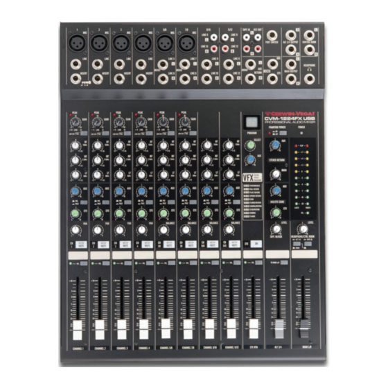
    BOUTONS DU PANNEAU AVANT - SECTION CONTROLE DE CANAL (1). TÉMOIN DE CRÊTE Ces témoins permettent de vérifier le niveau du signal d'entrée au canal. Les témoins de crête s’allument lorsque le signal d'entrée atteint 5 dB en dessous du point d'écrêtage du canal. Ces indicateurs montrent le niveau du signal après l’égaliseur et avant le fader.
  • Page 35 BOUTONS DU PANNEAU AVANT - SECTION CONTROLE DE CANAL (suite) (8). BOUTON PAN/BAL PAN (canal mono) Ce bouton effectue un panoramique du signal du canal à travers les bus maîtres L (gauche) et R (droite), déterminant ainsi la position du son perçu de ce canal dans le champ sonore de sortie stéréo. Si un bouton PAN est positionné à fond vers la gauche, par exemple, le son à...
  • Page 36 BOUTONS DU PANNEAU AVANT - SECTION DE COMMANDE PRINCIPALE (1). AFFICHAGE DU PROGRAMME VFX Les LED Programme affichent le numéro du programme d’effets sélectionné. Utilisez le tableau situé au-dessus du bouton ON/OFF VFX (EFX) pour rechercher les effets désirés. (2). BOUTON DE SÉLECTION DU PROGRAMME VFX Ce bouton programme sélectionne l'un des 100 effets numériques intégrés, pour chaque numéro que vous choisissez.
  • Page 37 BOUTONS DU PANNEAU AVANT - SECTION DE COMMANDE PRINCIPALE (suite) (11). Boutons de signaux de sonomètre (Interrupteur à bascule MAIN-ALT 3/4 et bouton TAPE IN) Ces commutateurs de sonomètre, ainsi que les boutons PFL des canaux, sélectionnent le signal qui est envoyé par le bouton CTRL ROOM/HEADPHONE aux connecteurs de sortie CONTROL ROOM, connecteur HEADPHONE et au sonomètre.
  • Page 38: Temoin D'alimentation

    BOUTONS DU PANNEAU AVANT - SECTION DE COMMANDE PRINCIPALE (suite) (18). TEMOIN D'ALIMENTATION Ce témoin s'allume lorsque le bouton d’alimentation est activé. (19). BOUTON D'ALIMENTATION FANTOME Ce bouton permet d’activer/désactiver l’alimentation fantôme. Si l’alimentation fantôme est activée, la table de mixage alimente tous les canaux dotés de connecteurs XLR d'entrée micro.
  • Page 39 BOUTONS DU PANNEAU AVANT – CONNECTEURS D’ENTREE/SORTIE (1). Connecteurs d’entrée canal Connecteur MIC Un connecteur 3 broches de type XLR est utilisé pour les entrées de microphones symétriques d'impédance faible. (Broche 1 : manchon, 2 : positif, 3 : négatif) CONNECTEURS D’ENTRÉE LIGNE SYMÉTRIQUES Un connecteur téléphonique ¼"...
  • Page 40 BOUTONS DU PANNEAU AVANT – CONNECTEURS D’ENTREE/SORTIE (suite) (5). CONNECTEURS TAPE IN Il s’agit de connecteurs RCA à broches pour l'entrée d’une source sonore stéréo. Utilisez ces connecteurs lorsque pour connecter un lecteur CD ou DAT (bande audionumérique) directement à la table de mixage pour le contrôle continu. REMARQUE : Vous pouvez régler le niveau du signal en utilisant le bouton TAPE IN de la section de commande principale.
  • Page 41: Boutons Du Panneau Arriere

    TAPE IN/USB. La connexion de la table de mixage audio à votre ordinateur est une procédure simple qui ne prend que quelques minutes. La table de mixage audio Cerwin-Vega étant compatible USB, vous pouvez utiliser un Mac ou un PC Windows. Vous trouverez des instructions détaillées sur la configuration de la table de mixage audio pour les ordinateurs MAC ou Windows dans les sections suivantes de ce manuel.
  • Page 42 INTERFACE AUDIO USB (Windows 7) 1. La première fois que vous branchez la table de table de mixage en définissant l'appareil par défaut mixage audio sur un port USB, Windows va installer les comme « CODEC audio USB ». pilotes universels pour ce port. Une info-bulle apparaîtra vous indiquant qu'il reconnaît la connexion et installe le pilote de l'appareil.
  • Page 43 INTERFACE AUDIO USB (Windows XP) 1. La première fois que vous branchez la table de 4. Pour utiliser la table de mixage audio comme appareil mixage audio sur un port USB, Windows va installer les d’entrée/sortie par défaut (pour les sons du système et pilotes universels pour ce port.
  • Page 44 INTERFACE AUDIO USB (MAC OS X) 1. Connectez la table de mixage audio à votre Mac via 4. Cliquez à présent sur l'onglet Entrée et sélectionnez un câble USB standard. Le témoin s'allume pour CODEC Audio USB. Vous remarquerez que le curseur indiquer qu'il est sous tension USB.
  • Page 45: Points À Retenir

    POINTS À RETENIR Dans tous les cas, utilisez un câble audio double blindage de bonne qualité. Vérifiez l'instabilité à la sortie. Connectez toujours les deux conducteurs aux deux extrémités et veiller à ce que le blindage n’est connecté qu’à une extrémité. Ne débranchez pas la mise à...
  • Page 46: Connexions

    CONNEXIONS Tableau A (TRS 1/4”) Manchon Anneau Pointe Insert Blindage Retour Envoi Ligne symétrique Terre Froid (-) Chaud (+) Ligne asymétrique Terre Chaud (+) Casque Manchon Droite Gauche Tableau B (XLR) Broche 1 Broche 2 Broche 3 Blindage/Terre Froid (-) Chaud (+)
  • Page 47: Connexions - Configurations Des Connecteurs Et Des Cables

    CONNEXIONS – CONFIGURATIONS DES CONNECTEURS ET DES CABLES...
  • Page 48: Applications - Enregistrement À Domicile

    APPLICATIONS – ENREGISTREMENT À DOMICILE Procédure de Configuration : 1. Avant de connecter les microphones et les instruments, assurez-vous que tous les appareils sont éteints. Assurez-vous également que tous faders des canaux et les faders maîtres de la table de mixage sont au niveau le plus faible.
  • Page 49 APPLICATIONS – REPRESENTATIONS EN LIVE...
  • Page 50: Schema De Principe

    SCHEMA DE PRINCIPE...
  • Page 51: Spécifications Générales

    3.4 kg (7.5 lbs) CVM-1224FXUSB Poids 5.6 kg (12.3 lbs) CVM-1624FXUSB 328 x 90 x 420 mm (12.9 x 3.5 x 16.5 in) CVM-1224FXUSB Dimensions (L x H x P) 436 x 90 x 420 mm (17.2 x 3.5 x 16.5 in) CVM-1624FXUSB...
  • Page 52: Impédance D'entrée

    SPÉCIFICATIONS GÉNÉRALES ENTREE Impédance Impédance Niveau d'entrée Connecteur d'entrée Type de connecteur d'entrée nominale nominal CH Mic 4 kΩ 50 ~ 600 Ω -50 dB Type XLR 3-31 symétrique Connecteur téléphonique CH Line 10 kΩ 600 Ω -30 dB (TRS) T=+ R=- S=GND Entrée micro stéréo 3 kΩ...
  • Page 53: Garantie

    GARANTIE Nous vous remercions d'avoir choisi l'une des marques Gibson Pro Audio (Stanton, KRK et Cerwin Vega!). Votre satisfaction est extrêmement importante pour nous. Nous sommes fiers d’être derrière la qualité de notre travail et nous apprécions que vous mettiez votre confiance en nous. L'enregistrement de votre produit nous aidera à garantir que vous êtes tenu au courant de nos dernières améliorations.
  • Page 54 GARANTIE (suite) CETTE GARANTIE N’EST ACCORDEE QU’A L'ACHETEUR AU DETAIL ORIGINAL ET NE PEUT ETRE TRANSFEREE OU CONCEDEE AUX PROPRIETAIRES ULTERIEURS. AFIN DE VALIDER VOTRE GARANTIE, EN TANT QUE CONDITION NECESSAIRE POUR BENEFICIER DE LA GARANTIE, VOUS DEVEZ ENREGISTRER VOTRE GARANTIE DANS LES QUINZE (15) JOURS SUIVANT LA DATE INITIALE DE L'ACHAT. LA FACTURE OU REÇU D'ACHAT DOIT ACCOMPAGNER TOUTES LES DEMANDES D’INTERVENTION SOUS GARANTIE.
  • Page 55: Garantie (Suite)

    GARANTIE (suite) Comment obtenir un service au titre de la garantie Service de garantie en dehors des États-Unis: Pour initier une réparation sous garantie, contactez le revendeur agréé Gibson Pro Audio auprès duquel vous avez acheté votre produit et suivez les règles de retour/garantie de ce dernier. Pour vous enregistrer votre produit acheté...
  • Page 56: Glossaire

    GLOSSAIRE atténuer Réduire ou rendre plus silencieux ; diminuer le niveau du signal auxiliaire (AUX) Envoyer un signal de sortie de la table de mixage à un équipement complémentaire qui fournit des fonctions supplémentaires. Généralement les flux de mixage sont implémentés par des boutons de contrôle de niveau rotatifs.
  • Page 57: Glossaire (Suite)

    GLOSSAIRE (suite) Un point de rupture dans le trajet du signal pour permettre la connexion de dispositifs externes, des insert processeurs de signaux par exemple ou d'autres table de mixages à des signaux de niveau ligne. Les niveaux nominaux peuvent être n'importe où entre -10 dBu à +6 dBu, généralement provenant d'une source à...
  • Page 58 CVM-1224FXUSB CVM-1624FXUSB MESA DE MEZCLAS PROFESIONAL...
  • Page 59: Instrucciones De Seguridad Importantes

    NOTA: Cerwin-Vega no puede responsabilizarse por los daños y/o incluyendo las pérdidas de datos provocadas por el uso inadecuado de la unidad y/o las aplicaciones proporcionadas para utilizarlas con ella.
  • Page 60 El dispositivo se haya caído o la carcasa haya sufrido daños. CERTIFICACIÓN REGLAMENTARIA Cerwin-Vega declara bajo su responsabilidad que este producto, con el cual se relaciona esta declaración, está en conformidad con las siguientes normas: Las Declaraciones de Conformidad pueden obtenerse en...
  • Page 61: Desembalaje E Instalación

    INTRODUCCIÓN ¡Le agradecemos la decisión de comprar la nueva mesa de mezclas profesional de la serie CV Mixer de Cerwin-Vega! Diseñada para una reproducción superior del sonido, la línea de mesas de mezclas profesionales de la serie CV Mixer proporciona audio de máxima calidad a un precio asequible. La serie CV Mixer ofrece un estándar de fiabilidad y eficiencia que la hacen ser la solución perfecta para cualquier DJ, músico e ingeniero de sonido.
  • Page 62 CONTROLES DEL PANEL FRONTAL – SECCIÓN DE CONTROL DE CANALES (1). INDICADOR LED DE PICOS Este indicador LED le permite comprobar el nivel de la señal de entrada al canal. El indicador de picos se ilumina cuando la señal de entrada alcanza 5dB por debajo del umbral de saturación del canal.
  • Page 63 CONTROLES DEL PANEL FRONTAL – SECCIÓN DE CONTROL DE CANALES (Cont.) (8). CONTROL PAN / BAL PAN (Canal Mono) Este control criba la señal del canal a través de los buses maestros Izdo. y Dcho., determinando así la posición de percepción del sonido desde ese canal en el campo de sonido estéreo de salida.
  • Page 64 CONTROLES DEL PANEL FRONTAL – SECCIÓN DE CONTROL PRINCIPAL (1). PRESENTACIÓN DEL PROGRAMA VFX La pantalla LED del programa le muestra el número del programa de efectos seleccionado. Use la tabla situada sobre el interruptor ‘VFX (EFX) ON’ para buscar los efectos deseados. (2).
  • Page 65 CONTROLES DEL PANEL FRONTAL – SECCIÓN DE CONTROL PRINCIPAL (cont.) (11). Interruptores de señal del Medidor de nivel (Conmutador ‘MAIN-ALT 3/4’ E INTERRUPTOR ‘TAPE IN’ Estos interruptores del medidor de nivel, junto con los interruptores PFL de canal, seleccionan la señal que se envía a través del control ‘CTRL ROOM/HEADPHONE’...
  • Page 66 CONTROLES DEL PANEL FRONTAL – SECCIÓN DE CONTROL PRINCIPAL (cont.) (18). INDICADOR ENCENDIDO (‘POWER’) Este indicador se ilumina cuando el interruptor de alimentación activado. (19). INTERRUPTOR DE CORRIENTE FANTASMA (‘PHANTOM’) Este interruptor activa o desactiva la alimentación fantasma. Si coloca el interruptor en la posición de encendido, el mezclador suministra alimentación a todos los canales con conectores XLR de entrada de micrófono.
  • Page 67 CONTROLES DEL PANEL FRONTAL – CONECTORES DE ENTRADA/SALIDA (1). Conectores de entrada de canal CONECTORES ‘MIC’ Un conector de 3 pines tipo XLR que se usa para las entradas de de micrófonos de baja impedancia balanceados. (Pin 1: Pantalla, 2: positivo, 3: negativo) CONECTORES BALANCEADOS DE ENTRADA DE LÍNEA Un conector de auriculares de ¼”...
  • Page 68 CONTROLES DEL PANEL FRONTAL – CONECTORES DE ENTRADA/SALIDA (cont.) (5). CONECTORES ‘TAPE IN’ Estos conectores de pines RCA introducen una fuente de sonido estéreo. Use estos conectores cuando desee conectar un CD o DAT directamente a la mesa de mezclas para su monitorización. NOTA: Puede ajustar el nivel de señal usando el control ‘TAPE IN’...
  • Page 69: Puerto Usb

    IN/USB’. La conexión de la mesa de mezclas de audio a su PC es un procedimiento simple que lleva solo unos minutos. Ya que la mesa de mezclas de audio Cerwin-Vega es compatible USB, puede usar un PC con sistema operativo Windows o MAC.
  • Page 70 INTERFAZ DE AUDIO USB (Windows 7) 1. La primera vez que conecte la mesa de mezclas de dispositivo por defecto para los altavoces en la ventana audio en un puerto USB, Windows instalará los del Mezclador de Volumen. controladores universales para ese puerto. Aparecerá un cuadro de diálogo emergente, diciéndole que se reconoce la conexión y que se instalará...
  • Page 71 INTERFAZ DE AUDIO USB (Windows XP) 1. La primera vez que conecte la mesa de mezclas de 4. Para usar la mesa de mezclas como su dispositivo de audio en un puerto USB, Windows instalará los entrada/salida por defecto (para los sonidos del sistema controladores universales para ese puerto.
  • Page 72 INTERFAZ DE AUDIO USB (MAC OS X) 1. Conecte la mesa de mezclas a su MAC usando un 4. Ahora, haga ‘clic’ en la pestaña de Entrada y cable USB estándar. El LED se iluminará indicando que seleccione ‘USB Audio CODEC’. Puede comprobar que el está...
  • Page 73 PUNTOS PARA RECORDAR En todos los casos, use un cable de audio con doble apantallamiento de buena calidad. Compruebe la estabilidad de la salida. Conecte siempre ambos conductores en ambos terminales, y asegúrese de que la conexión a tierra se establece solamente en uno de los terminales.
  • Page 74 CONEXIONES Tabla A (1/4” TRS) Manga Anillo Punta Inserción Pantalla Retorno Envío Línea balanceada Tierra Negativo (-) Positivo (+) Línea desbalanceada Tierra Sin valor Positivo (+) Auriculares Camisa Derecho Izquierdo Tabla B (XLR) Pin 1 Pin 2 Pin 3 Pantalla/Tierra Negativo (-) Positivo (+)
  • Page 75 CONEXIONES – CONFIGURACIONES DEL CONECTOR Y CABLE...
  • Page 76 APLICACIONES – GRABACIONES DOMÉSTICAS Procedimiento de configuración 1. Antes de conectar los micrófonos e instrumentos, cerciórese de que todos los dispositivos están apagados. Asegúrese también de que todos los faders de canal y de control maestro están al mínimo. Para cada conexión, conecte un extremo del cable al micrófono o instrumento pertinente y conecte el otro extremo al conector de entrada apropiado en la mesa de mezclas.
  • Page 77 APLICACIONES – ACTUACIONES EN DIRECTO...
  • Page 78: Diagrama De Bloques

    DIAGRAMA DE BLOQUES...
  • Page 79: Especificaciones Generales

    3.4 kg (7.5 lbs) CVM-1224FXUSB Peso: 5.6 kg (12.3 lbs) CVM-1624FXUSB 328 x 90 x 420 mm (12.9 x 3.5 x 16.5 in) CVM-1224FXUSB Dimensiones (A x A x P) 436 x 90 x 420 mm (17.2 x 3.5 x 16.5 in) CVM-1624FXUSB...
  • Page 80 ESPECIFICACIONES ENTRADA Impedancia de Impedancia Nivel nominal de Conector de entrada Tipo de conector entrada nominal entrada Canal Mic 4 kΩ 50 ~ 600 Ω -50 dB XLR 3-31 tipo balanceado Clavija de auriculares (TRS) Canal Line 10 kΩ 600 Ω -30 dB Punta=(+) Anillo=(-) S=Tierra Entrada Mic.
  • Page 81 GARANTÍA Gracias por elegir una de las marcas de Gibson Pro Audio (Stanton, KRK o Cerwin Vega!). Su satisfacción es muy importante para nosotros. Nosotros permanecemos con agrado tras la calidad de nuestro trabajo y apreciamos que usted confíe en nosotros. Registrando su mercancía nos ayudará a garantizarle que estará actualizado con nuestros últimos avances.
  • Page 82 GARANTÍA (continuación) Gibson garantizará todas las piezas de repuesto y las reparaciones durante noventa (90) días desde la fecha del envío original. En el caso improbable de que su mercancía sea destruida, perdida o dañada sin posibilidad de reparación mientras esté en posesión de Gibson o de uno de los Centros de Servicio autorizados Gibson Pro Audio, Gibson reemplazará...
  • Page 83 GARANTÍA (continuación) Cómo obtener Servicio por Garantía Servicio de Garantía fuera de los Estados Unidos. Para iniciar una reparación por garantía, por favor contacte con su distribuidor autorizado Gibson Pro Audio al que le compró la mercancía, y cumpla con la política de devolución/garantía del distribuidor. Servicio por garantía de la mercancía comprada en un punto de venta autorizado Gibson Pro Audio en los EE.UU.: En el caso de un mal funcionamiento de su mercancía Gibson Audio Pro, el Vendedor o el Propietario deben llamar al número de Atención al Cliente 1-8004GIBSON (1-800444-2766) y obtener un Número de Autorización de Devolución...
  • Page 84 GLOSARIO Atenuar Reducir o hacer más silencioso. Bajar el nivel de señal Auxiliar (aux) Enviar una señal de salida desde la mesa de mezclas a un equipo suplementario que proporciona capacidades adicionales. Normalmente las señales se implementan mediante controles de nivel giratorios. Un retorno aux en la mesa de mezclas se usa para conectarla a la salida del equipo suplementario.
  • Page 85 GLOSARIO (continuación) Inserción Punto de ruptura en la ruta de la señal para permitir la conexión de dispositivos externos, por ejemplo procesadores de señal u otras mesas de mezcla en las señales de nivel de línea. Los niveles nominales pueden ser cualquiera entre -10dBu hasta +6dBu, normalmente procedentes de una fuente de baja impedancia.
  • Page 86 CVM-1224FXUSB CVM-1624FXUSB PROFESSIONELLEN AUDIO-MIXER...
  • Page 87: Wichtige Sicherheitshinweise

    WICHTIGE SICHERHEITSHINWEISE VORSICHT: DER BLITZ IM GLEICHSEITIGEN DREIECK SOLL DEN BENUTZER VOR NICHT ABGESCHIRMTER GEFÄHRLICHER SPANNUNG WARNEN, DIE IM INNEREN DES GERÄTS VORHANDEN IST UND ZU EINEM STROMSCHLAG FÜHREN KANN. ACHTUNG: DAS AUSRUFEZEICHEN INNERHALB DES GLEICHSEITIGEN DREIECKS SOLL DEN BENUTZER AUF WICHTIGE WARTUNGSANWEISUNGEN IN DER BEILIEGENDEN DOKUMENTATION AUFMERKSAM MACHEN.
  • Page 88 Es scheint, dass das Gerät nicht richtig funktioniert oder eine deutliche Leistungsänderung aufweist. Das Gerät wurde fallen gelassen oder das Gehäuse ist beschädigt. Cerwin-Vega erklärt unter unserer alleinigen Verantwortung, dass dieses Produkt, auf das sich die Erklärung bezieht, mit den folgenden Normen übereinstimmt: Die Konformitätserklärung kann schriftlich angefordert werden, wenn Sie einen Brief an folgende Adresse richten: Gibson Europe BV...
  • Page 89 EINFÜHRUNG Wir danken Ihnen, dass Sie sich für die neue professionelle Audiomischpultserie CV von Cerwin-Vega entschieden haben! Für eine phantastische Klangwiedergabe entwickelt, bietet die professionelle CV Audiomischpulteserie beste Klangqualität zu einem erschwinglichen Preis. Die CV Mischpultserie bietet einen Standard für Zuverlässigkeit und Effizienz, welcher sie zu idealen Lösung für jeden DJ, Musiker und Toningenieur macht.
  • Page 90 BEDIENELEMENTE GERÄTEVORDERSEITE – KANAL-KONTROLLABSCHNITT (1). PEAK-LED-ANZEIGE Mit dieser LED Anzeige können Sie den Pegel des Eingangssignals zum Kanal prüfen. Die Peak-Anzeige leuchtet auf, wenn das Eingangssignal 5dB unter dem Clipping-Punkt des Kanals liegt. Diese Anzeige zeigt den Pegel des Post-EQ/Pre-Fadersignals an. Wenn die PEAK-Anzeige bei hohen Transienten länger aufleuchtet, müssen Sie den GAIN-Regler benutzen, um die Eingangsempfindlichkeit des Kanals zu verringern.
  • Page 91 BEDIENELEMENTE GERÄTEVORDERSEITE – KANAL-KONTROLLABSCHNITT (Fortsetzung) (8). PAN/BAL-REGLER PAN (Mono-Kanal) Dieser Regler schwenkt das Kanalsignal zwischen Masterbus-L und -R, folglich bestimmt er die wahrgenommene Klangposition dieses Kanals im Ausgangs-Stereoklangfeld. Wenn beispielsweise ein PAN-Regler ganz nach links eingestellt ist, wird der Ton jenes Kanals nur vom linken Lautsprechersystem ausgegeben. Wenn er ganz nach rechts eingestellt ist, wird der Ton nur vom rechten Lautsprechersystem ausgegeben.
  • Page 92 BEDIENELEMENTE GERÄTEVORDERSEITE – MAIN-REGLERABSCHNITT (1). VFX-PROGRAMMANZEIGE Die Programm-LED zeigt die Nummer des ausgewählten Effektprogamms an. Verwenden Sie die Tabelle über der VFX (EFX) ON/OFF-Taste, um die gewünschten Effekte zu suchen. (2). VFX PROGRAMM-AUSWAHLSCHALTER Dieser Programmauswahlschalter wählt die Nummer eines der 100 integrierten digitalen Effekte. Die VFX-Programme verwenden einen hochwertigen digitalen 24-Bit-Effektprozessor mit Effekten in Studioqualität, wie Delay, Chorus und Reverb.
  • Page 93 BEDIENELEMENTE GERÄTEVORDERSEITE – MAIN-REGLERABSCHNITT (Fortsetzung) (11). Pegelanzeigen-Signaltasten (MAIN-ALT 3/4-Umschalter und TAPE IN-Taste) Diese Pegelanzeigentasten wählen zusammen mit den Kanal-PFL-Tasten das Signal aus, das über das CTRL ROOM/HEADPHONE-Regler an die CONTROL ROOM-Buchsen, die HEADPHONE-Buchse und die Pegelanzeige gesendet wird. Die folgenden Abbildungen zeigen die Tasteneinstellungen entsprechend zur Signalauswahl. (12).
  • Page 94 BEDIENELEMENTE GERÄTEVORDERSEITE – MAIN-REGLERABSCHNITT (Fortsetzung) (18). BETRIEBSANZEIGE Die Anzeige leuchtet auf, wenn der Netzschalter eingeschaltet wurde. (19). PHANTOMSPEISUNGSTASTE Die Taste schaltet die Phantomspeisung ein oder aus. Wenn Sie die Taste einschalten, versorgt das Mischpult alle Kanäle mit Strom, die XLR-Mikrofoneingangsbuchsen besitzen. Schalten Sie diese Taste ein, wenn Sie ein oder mehrere Kondensatormikrofone verwenden.
  • Page 95 BEDIENELEMENTE GERÄTEVORDERSEITE – EIN-/AUSGANGSANSCHLÜSSE (1). Kanaleingangsbuchsen MIC-BUCHSEN Für symmetrische niederohmige Mikrofoneingänge wird eine 3-polige XLR-Buchse verwendet. (Pin 1: Mantel, 2: heiß, 3: kalt) SYMMETRISCHE LINE IN-EINGANGSBUCHSEN Für symmetrische oder unsymmetrische Signale mit Line-Pegel wird eine standardmäßige 6,3 mm-Klinkenbuchse verwendet. Zu den Signalen mit Line-Pegel gehören beispielsweise die meisten elektronischen Keyboards, Synthesizer, Turn-Tables (mit entsprechenden Vorverstärkern), Tape Decks und die Line-Ausgänge von anderen Mischpulten.
  • Page 96 BEDIENELEMENTE GERÄTEVORDERSEITE – EIN-/AUSGANGSANSCHLÜSSE (Fortsetzung) (5). TAPE IN-BUCHSEN An diese RCA-Buchse wird eine Stereo-Tonquelle angeschlossen. Verwenden Sie diese Buchsen, wenn Sie einen CD- oder DAT-Player zur Überwachung direkt am Mischpult anschließen möchten. HINWEIS: Sie können den Signalpegel mittels des TAPE IN-Reglers im MAIN-Reglerabschnitt einstellen. (6).
  • Page 97: Power-Schalter

    Wiedergabeeinstellung erfolgt mittels des TAPE IN/USB-Pegelreglers. Der Anschluss des Audiomischpults am Computer ist ein einfacher Vorgang und dauert nur wenige Minuten. Da das Cerwin-Vega Audiomischpult mit USB kompatibel ist, können Sie entweder einen MAC oder Windows-PC verwenden. In den folgenden Abschnitten dieser Bedienungsanleitung finden Sie detaillierte Anweisungen zum Einrichten des Audiomischpult an entweder MAC- oder Windows-Computern.
  • Page 98 USB-AUDIOSCHNITTSTELLE (Windows 7) 1. Wenn Sie das Audiomischpult das erste Mal an einen Lautstärkemixerfenster auf „USB Audio CODEC“ USB-Port anschließen, installiert Windows den eingestellt ist. universellen Treiber für den Port. Ein Balloon-Tip öffnet sich und weist Sie darauf hin, dass es die Verbindung erkennt und den Gerätetreiber installieren wird.
  • Page 99 USB-AUDIOSCHNITTSTELLE (Windows XP) 1. Wenn Sie das Audiomischpult das erste Mal an einen Standardeingabe-/Ausgabegerät zu verwenden (für USB-Port anschließen, installiert Windows den Systemklänge und Programme, wie den Audiorecorder), universellen Treiber für den Port. Ein Balloon-Tip öffnet achten Sie darauf, dass im Eigenschaftenfenster das sich und weist Sie darauf hin, dass ein USB-Audiocodec Standardgerät für Wiedergabe und Aufnahme auf „USB gefunden wurde.
  • Page 100 USB-AUDIOSCHNITTSTELLE (MAC OS X) 1. Schließen Sie das Audiomischpult mittels eines 4. Klicken Sie jetzt in die Eingangsregisterkarte und gewöhnlichen USB-Kabels an Ihren MAC an. Die LED wählen Sie den USB Audio CODEC. Sie dürfen bemerkt leuchtet auf, dass die USB angeschlossen ist. Der MAC haben, dass sich der Lautstärkeschieberegler erkennt das USB-Audiogerät und installiert automatisch selbstständig auf den vollen Pegel eingestellt hat.
  • Page 101: Wichtige Punkte

    WICHTIGE PUNKTE Verwenden Sie auf alle Fälle hochwertige Audiokabel mit doppelter Abschirmung. Prüfen Sie auf Instabilitäten am Ausgang. Verbinden Sie stets beide Litzen an beiden Enden und achten Sie darauf, dass die Abschirmung nur an einem Ende angeschlossen ist. Schließen Sie die Haupterdleitung nicht an jedem Gerät an. Dies wird sowohl für die Sicherheit als auch als Abschirmungsreturn zum Systemstartpunkt benötigt.
  • Page 102 ANSCHLÜSSE Tabelle A (6,3 mm TRS) Mantel Ring Spitze Insert Schirm Return Send Symmetrische Leitung Masse Kalt (-) Heiß (+) Unsymmetrische Leitung Masse nicht verfügbar Heiß (+) Kopfhörer Mantel Rechts Links Tabelle B (XLR) Pin 1 Pin 2 Pin 3 Abschirmung/Masse Kalt (-) Heiß...
  • Page 103 ANSCHLÜSSE – VERBINDER UND KABELKONFIGURATIONEN...
  • Page 104 ANWENDUNGEN – HEIM-AUFNAHME Setupverfahren 1. Achten Sie vor dem Anschluss der Mikrofone und Instrumente darauf, dass alle Geräte ausgeschaltet sind. Stellen Sie auch sicher, dass alle Kanalfader und Masterregelungsfader des Mischpults heruntergezogen wurden. 2. Schließen Sie für jeden Anschluss ein Ende des Kabels an das entsprechende Mikrofon oder Instrument und das andere Ende an die entsprechende Eingangsbuchse am Mischpult an.
  • Page 105 ANWENDUNGEN – LIVE-PERFORMANCE...
  • Page 106 BLOCKDIAGRAMM...
  • Page 107 3.4 kg (7.5 lbs) CVM-1224FXUSB Gewicht 5.6 kg (12.3 lbs) CVM-1624FXUSB 328 x 90 x 420 mm (12.9 x 3.5 x 16.5 in) CVM-1224FXUSB Abmessungen (B x H x T): 436 x 90 x 420 mm (17.2 x 3.5 x 16.5 in) CVM-1624FXUSB...
  • Page 108: Technische Daten

    TECHNISCHE DATEN EINGANG Eingangsanschluss Eingangsimpedanz Nennimpedanz Nenneingangspegel Anschlussart CH Mic 4 kΩ 50 - 600 Ω -50 dB XLR 3-31 symmetrisch Klinkenstecker (TRS) CH Line 10 kΩ 600 Ω -30 dB T = heiß R = kalt S = Masse Stereoeingang Mic 3 kΩ...
  • Page 109 GARANTIE Vielen Dank, dass Sie sich für eine der Gibson Pro Audio Marken (Stanton, KRK, oder Cerwin Vega!) entschieden haben. Ihre Zufriedenheit ist uns besonders wichtig. Wir stehen voll und ganz hinter der Qualität unserer Arbeit und freuen uns, dass Sie uns vertrauen. Die Registierung Ihrer Waren hilft uns, zu garantieren, dass Sie auf dem neuesten Stand bezüglich unserer neuesten Fortschritte bleiben.
  • Page 110 GARANTIE (Fortsetzung) DIESE GARANTIE WIRD NUR AUF DEN ORIGINAL WIEDERVERKÄUFER AUSGEWEITET UND KANN NICHT AUF NACHFOLGENDE BESITER ÜBERTRAGEN ODER DIESEN ÜBEREIGNET WERDEN. UM IHRE GARANTIE ZU VALIDIEREN UND AS EINE BEDINGUNG; DIE DER HIER VORANGEGANGENEN GARANTIEABDECKUNG; MÜSSEN SIE IHRE GARANTIE INNERHALB VON VIERZEHN (14) TAGEN NACH DEM ORIGINALKAUFDATUM REGISTIEREN LASSEN.
  • Page 111 GARANTIE (Fortsetzung) Wie erhält man eine Garantieleistung? Garantieleistung außerhalb der USA. Für eine Garantiereparatur wenden Sie sich bitte an den autorisierten Gibson Pro Audio Händler, wenden Sie sich bitte an den autorisierten Gibson Pro Audio Händler, von dem Sie Ihre Ware gekauft haben und befolgen Sie die Rücksende-/Garantiepolitik des Händlers.
  • Page 112 GLOSSAR Abschwächen Verringern oder leiser stellen. Die Signalhöhe verringern. Auxiliary (AUX) Sendet ein Ausgangssignal vom Mischpult zu weiteren Geräten, die zusätzliche Fähigkeiten bieten. Normalerweise werden die Feeds zum Mix mit Drehpegelreglern durchgeführt. Ein Aux-Return am Mischpult dient zum Anschluss des Ausgangs von zusätzlichen Geräten. Balance Die relativen Pegel der linken und rechten Kanäle eines Stereosignals.
  • Page 113 GLOSSAR (Fortsetzung) Insert Ein Unterbrechungspunkt im Signalpfad, der den Anschluss externer Vorrichtungen zulässt, z. B. Signalprozessoren oder andere Mischpulte mit Linepegelsignalen. Nominalpegel können zwischen -10 dBu bis + 6 dBu liegen und kommen gewöhnlich von einer Quelle mit niedriger Impedanz. Pan (Pot) Abkürzung von „Panorama“: Kontrolle der Pegel, die an die linken und rechten Ausgänge gesendet werden.
  • Page 114 Note(s): Remarque(s): Nota(s): Hinweise:...
  • Page 115 Note(s): Remarque(s): Nota(s): Hinweise:...
  • Page 116 Ein Mitglied der Gibson-Markenfamilie. This document is copyright protected. No part of this manual may be copied or reproduced in any form without prior written consent from CERWIN-VEGA. CERWIN-VEGA shall not be liable for operational, technical, or editorial errors/omissions made in this document.

Ce manuel est également adapté pour:

Cvm-1624fxusb

Table des Matières