Table des Matières

Publicité

Les langues disponibles

Les langues disponibles

Liens rapides

GEBRAUCHSANLEITUNG
Originalversion
OPERATING MANUAL
MODE D'EMPLOI
MANUAL DE INSTRUCCIONES
TITRONIC® 500
KOLBENBÜRETTE
PISTON BURETTE
BURETTE À PISTON
BURETA DE ÈMBOLO

Publicité

Table des Matières
loading

Sommaire des Matières pour SI Analytics TITRONIC 500

  • Page 1 GEBRAUCHSANLEITUNG Originalversion OPERATING MANUAL MODE D’EMPLOI MANUAL DE INSTRUCCIONES TITRONIC® 500 KOLBENBÜRETTE PISTON BURETTE BURETTE À PISTON BURETA DE ÈMBOLO...
  • Page 2 Toutes les indications comprises dans ce mode d’emploi sont données à titre indicatif au moment de l'impression. Pour des raisons techniques et/ou commerciales ainsi qu'en raison des dispositions légales existantes dans les différents pays, SI Analytics se réserve le droit d'effectuer des suppléments concernant la ®...
  • Page 3: Table Des Matières

    ® Technische Eigenschaften der Kolbenbürette TITRONIC 500 ......5 Zusammenfassung ........................5 ® Technische Eigenschaften der Kolbenbürette TITRONIC 500 ..........6 Warn- und Sicherheitshinweise ....................8 Aufstellen und Inbetriebnahme ................9 Auspacken und Aufstellen der Kolbenbürette ................9 Montage des Stativfußes Z 300 (Option) .................. 9 Anschluss und Montage der Bürette und des Magnetrührers TM 235 ........
  • Page 4 Datenkommunikation über die RS-232- und USB-B- Schnittstelle ...... 49 Allgemeines ..........................49 Verkettung mehrerer Geräte — „Daisy Chain Konzept“ ............49 Befehlsliste für RS-Kommunikation ..................50 Anschluss von Analysenwaagen und Druckern ........... 51 Anschluss von Analysenwaagen ..................... 51 Waagedateneditor ........................52 Anschluss von Druckern ......................
  • Page 5: Technische Eigenschaften Der Kolbenbürette Titronic ® 500

    ® Technische Eigenschaften der Kolbenbürette TITRONIC 1.1 Zusammenfassung ® Die TITRONIC 500 ist eine Kolbenbürette und für folgende Anwendungen geeignet: − Manuelle Titrationen mit oder ohne Berechnung des Ergebnisses − Dosierungen − Lösungen herstellen − ® Verwendung als Dosierbürette mit dem Titrator TitroLine 7000 −...
  • Page 6 1200, 2400, 4800, 9600, 19200 (Default 4800 Baud) Adresse: einstellbar, (0 bis 15, Defaultwert:01) RS-232-1 für Computer, Eingang Daisy Chain  RS-232-2 Geräte von SI Analytics, Titrator TitroLine 7000,    - Kolbenbüretten TITRONIC 500, TITRONIC 110 plus, TITRONIC...
  • Page 7 Stand 21.11.2013 Polypropylen Gehäuse-Werkstoff: Kunststoff beschichtet Fronttastatur: Gehäuse-Abmessungen: 15,3 x 45 x 29,6 cm (B x H x T), Höhe mit Wechseleinheit ca. 2,3 kg für Grundgerät Gewicht: ca. 3,5 kg für komplettes Gerät mit Wechseleinheit (mit leerer Reagenzienflasche) Umgebungstemperatur: + 10 ... + 40 °C für Betrieb und Lagerung Klima: Luftfeuchtigkeit nach EN 61 010, Teil 1: 80 % für Temperaturen bis 31 °C linear abnehmend bis zu 50 % relativer Feuchte bei einer Temperatur von...
  • Page 8: Warn- Und Sicherheitshinweise

    1.3 Warn- und Sicherheitshinweise ® Das Gerät TITRONIC 500 entspricht der Schutzklasse III. Es ist gemäß EN 61 010 - 1, Teil 1, Sicherheitsbestimmungen für elektrische Mess-, Steuer-, Regel- und Laborgeräte, gebaut und geprüft und hat das Werk in sicherheitstechnisch einwandfreiem Zustand verlassen. Um diesen Zustand zu erhalten und einen gefahrlosen Betrieb sicherzustellen, muss der Anwender die Hinweise und Warnvermerke beachten, die in dieser Gebrauchsanleitung enthalten sind.
  • Page 9: Aufstellen Und Inbetriebnahme

    Kapitel 4 - Methodenparameter Aufstellen und Inbetriebnahme 2.1 Auspacken und Aufstellen der Kolbenbürette Die Kolbenbürette und alle Zubehörteile sowie die Peripheriegeräte sind werkseitig sorgfältig auf Funktion und Maßhaltigkeit geprüft. Bitte achten Sie darauf, dass auch die kleinen Zusatzteile aus der Verpackung restlos entnommen werden. Den Lieferumfang entnehmen Sie bitte der beigefügten Packliste.
  • Page 10: Anschluss Und Montage Der Bürette Und Des Magnetrührers Tm 235

    2.3 Anschluss und Montage der Bürette und des Magnetrührers TM 235 Das Niederspannungskabel des Netzteils TZ 1853 wird in die mittlere 12 V Buchse, Buchse „in“, (siehe auch Abb. 4 Rückwand, Kap. 2.5), auf der Rückseite der Bürette eingesteckt. Danach das Netzteil in die Netzsteckdose einstecken.
  • Page 11: Anschlüsse Der Kolbenbürette. Kombination Mit Zubehör Und Weiteren Geräten

    5) „out“: Anschluss des Magnetrührers TM 235 6) Zwei RS232 Schnittstellen, 4-polig (Mini-DIN): RS1 für den Anschluss an den PC RS2 für den Anschluss einer Waage und weiterer Geräte von SI Analytics (Büretten, Probenwechsler) 2.5.3 Anschluss eines Druckers Drucker mit USB-Schnittstelle werden an einer der beiden USB-A Schnittstellen angeschlossen. Die Drucker müssen eine HP PCL -Emulation (3, 3GUI, 3 enhanced, 5, 5e) enthalten.
  • Page 12: Einstellen Der Landessprache

    2.6 Einstellen der Landessprache Werkseitig ist Englisch als Sprache voreingestellt. Nach dem die Kolbenbürette eingeschaltet und der Startvorgang beendet ist, erscheint das Hauptmenü: Abb. 5 Mit <SYS/<F7> bzw. über <MODE> und dann <Systemeinstellungen> wechselt man zu den Systemeinstellungen. Das erste Menü ist gleich die Einstellung der Landessprache: Abb.
  • Page 13: Wechselaufsatz Wa

    Kapitel 4 - Methodenparameter 2.7 Wechselaufsatz WA Abb. 8 1) TZ 3871 - Ansaugschlauch 2) TZ 3872 - Verbindungsschlauch 3) TZ 3873 - Dosierschlauch ohne Dosierspitze und Halter; TZ 3874.- Dosierschlauch mit Dosierspitze und Halter 4) TZ 3801 - Ventilabdeckung 5) TZ 3000 - 3/2-Wege Ventil 6) TZ 2003 - Trockenrohr 7) TZ 3802 - Schraubkappe GL 45 mit Bohrung, inkl.
  • Page 14: Aufsetzen Und Austauschen Eines Wechselaufsatzes

    2.8 Aufsetzen und Austauschen eines Wechselaufsatzes Die Titratoreinheit enthält ein RFID Lesegerät und die Wechselaufsätze enthalten alle eine RFID Transponder. In diesem Transponder können folgende Informationen gespeichert werden: • Aufsatzgröße (nicht veränderbar) • Aufsatz ID (nichtveränderbar) • Reagenzname (default: Leerzeichen •...
  • Page 15: Abnahme Eines Wechselaufsatzes

    Kapitel 4 - Methodenparameter Abb. 9.c 2.8.2 Abnahme eines Wechselaufsatzes Die Abnahme des Wechselaufsatzes geschieht in der umgekehrten Reihenfolge: • Links auf die schwarze Taste drücken und den Wechselaufsatz nach vorne ziehen wie in Abb. 9.c – 9.a abgebildet. ! Wichtig: Die Abnahme des Wechselaufsatzes ist nur möglich wenn sich der Kolben in der unteren Position befindet (Nullposition).
  • Page 16 Bei der ersten Verwendung ist es empfehlenswert, hier zumindest den Namen des verwendeten Reagenzes einzutragen. Dazu bestätigt man die Auswahl „Reagenz“ mit <ENTER> und tippt den Namen und eventuell die Konzentration ein (Abb. 12). Abb. 12 Mit <OK>/<ENTER> bestätigen (Abb. 12). Nach der optionalen Eingabe weiterer Parameter (zu weiteren Details zur Dateneingabe siehe Kapitel 5.1) verlässt man das Reagenzienmenü...
  • Page 17: Erstbefüllen Bzw. Spülen Des Kompletten Wechselaufsatzes

    Kapitel 4 - Methodenparameter Abb. 15 2.9 Erstbefüllen bzw. Spülen des kompletten Wechselaufsatzes Das Erstbefüllen der Wechseleinheit erfolgt durch das Spülprogramm <Spülen>. Vom Hauptmenü (Abb. 16) Abb. 16 gelangt man durch Drücken der <MODE> -Taste in das Methoden-/Systemmenü (Abb. 17) Abb.
  • Page 18 Abb. 18 Die Auswahl mit <ENTER> bestätigen: Abb. 19 Nun kann man die Anzahl der Spülzyklen auswählen (Abb. 19). Für eine Erstbefüllung muss man mindestens zweimal Spülen. Den Spülvorgang (Abb. 20) kann man jederzeit mit <STOP> abbrechen und anschließend mit <START>...
  • Page 19: Austausch Des Glaszylinders Und Des Ptfe-Kolbens

    Kapitel 4 - Methodenparameter 2.10 Austausch des Glaszylinders und des PTFE-Kolbens Der Austausch des Glaszylinders und des Kolbens gelingt ohne zusätzliches Werkzeug. In Einzelfällen ist die Verwendung des Kolbenziehers notwendig. • Den Wechselaufsatz vom Gerät abnehmen. • Der Schlauch zwischen Glaszylinder und Ventil vom Glaszylinder abschrauben. •...
  • Page 20 Abb. 22 b Grundsätzlich ist darauf zu achten, dass in einen Wechselaufsatz nur die vorgesehene Zylindergröße montiert werden darf, weil sonst die im Wechselaufsatz gespeicherte Codierung nicht mehr mit der Zylindergröße übereinstimmt. Die Folge ist eine falsche Dosierung. Es wird aus Gründen der Dosier- und Analysengenauigkeit empfohlen, stets auch die PTFE-Kolben mit auszutauschen, wenn ein defekter Glaszylinder erneuert wird.
  • Page 21: Das Arbeiten Mit Der Kolbenbürette Titronic ® 500

    Kapitel 4 - Methodenparameter ® Das Arbeiten mit der Kolbenbürette TITRONIC 3.1 Fronttastatur Mit Ausnahme von alphanumerischen Eingaben (a-z, A-Z, 0-9) und einigen wenigen Funktionen, können alle Funktionen auch über die Fronttastatur ausgeführt werden. Auswahl der Methoden, Spülen, Systemeinstellungen <Mode>: Ändern der aktuellen Methode, neue Methode, Methode kopieren und löschen <EDIT>: Mit <ESC>...
  • Page 22: Handtaster

    3.3 Handtaster Der Handtaster („Maus“, Abb. 23) wird bei der manuellen Titration benötigt. Er kann aber auch zum Start von Dosier- und anderen Methoden verwenden werden. Abb. 23 Modus Schwarze Taste Graue Taste Manuelle Titration Start der Titration, Einzelsschritte Füllen und kontinuierliches Titrieren (siehe Stopp der Titration mit Auswertung Kap.
  • Page 23: Menüstruktur

    Kapitel 4 - Methodenparameter <F2>/<STOP> Stopp der aktuellen Methode <F3>/<EDIT> Ändern der aktuellen Methode, neue Methode, Methode kopieren <F4>/<FILL> Füllen des Aufsatzes Anzeige und Änderung der Waagedaten <F5>/ <F6>/<MODE> Auswahl der Methoden, Spülen, Systemeinstellungen <F7>/<SYS> Systemeinstellungen (Sprachauswahl, Uhrzeit/Datum..) ® <F8/<CAL> Keine Funktion bei TITRONIC <F9>/ Vorzeichenwechsel...
  • Page 24 Abb. 25 Hier kann • die aktuelle Methode verändert • eine neue Methode erstellt • Standardmethoden aufgerufen und abgespeichert • eine bestehende Methode kopiert oder gelöscht werden Die Untermenüs werden mit <↓> und <↑>- Tasten angewählt und mit <OK>/<ENTER> die Auswahl bestätigt. Mit <ESC>...
  • Page 25: Hauptmenü

    Kapitel 4 - Methodenparameter Abb. 28 3.6 Hauptmenü Nach dem Einschalten erscheint immer das Hauptmenü. Es wird immer die zuletzt verwendete Methode angezeigt (Abb. 29). In diesem Fall eine Titrationsmethode. Abb. 29 3.6.1 Manuelle Titration Die manuelle Titration wird immer mit dem Handtaster, der so genannten „Maus“ durchgeführt. Eine manuelle Titration ohne Handtaster ist nicht möglich.
  • Page 26 Abb. 31 Abb. 32 Die Waagedaten können mit Hilfe der Fronttastatur oder der externen Tastatur eingegeben werden. Die Eingabe wird mit <OK>/<ENTER> bestätigt. Bei automatischer Waagedatenübernahme werden die Einwaagen aus dem Waagedatenspeicher ausgelesen. Falls keine Waagedaten im Speicher vorhanden sind, wird eine Meldung angezeigt, dass keine Waagedaten vorhanden sind (Abb.
  • Page 27 Kapitel 4 - Methodenparameter Abb. 34 Mit der schwarzen Taste des Handtasters („Maus“) wird die Zugabegeschwindigkeit kontrolliert. Mit einem einzelnen Tastendruck bis zur ersten Stufe wird ein Stepp ausgeführt. Je nach Aufsatzgröße ist das 0,0005 ml (WA 05), 0,001 ml (WA 10), 0,002 ml (WA 20) und 0,005 ml (WA 50). Hält man die schwarze Taste auf der ersten Stufe gedrückt, wird kontinuierlich langsam zutitriert.
  • Page 28: Dosierung

    Mit <ESC> gelangt man wieder zurück in das Startmenü und kann sofort die nächste manuelle Titration starten. Der Wechselaufsatz wird automatisch gefüllt. 3.6.2 Dosierung Eine Dosiermethode wird mit <START>/<F1> oder mit der schwarzen Taste des Handtasters („Maus“) gestartet. Abb. 37 Abb.
  • Page 29: Lösungen Ansetzen

    Kapitel 4 - Methodenparameter Die nächste Dosierung kann dann sofort gestartet werden. Der Aufsatz wird nicht automatisch nach der Dosierung gefüllt, es sei denn das maximale Zylindervolumen ist erreicht, oder die automatische Fülloption ist eingeschaltet. Mit <FILL> kann der Aufsatz jederzeit gefüllt werden. Eine Dosierung kann auch über die <DOS>/<F10>...
  • Page 30: Methodenparameter

    Abb. 44 Abb. 45 Ist das berechnete Volumen größer als das maximal eingestellte Volumen, erscheint eine Fehlermeldung und es wird aus Sicherheitsgründen nicht dosiert: Abb. 46 Methodenparameter Vom Hauptmenü aus (Abb. 43/Abb. 24) gelangt man <EDIT>/<F3> in die Methodenparameter: Abb. 47...
  • Page 31: Methode Editieren Und Neue Methode

    Kapitel 4 - Methodenparameter 4.1 Methode editieren und neue Methode Bei Anwahl von <Methode editieren> oder <neue Methode> gelangt man zur Änderung bzw. Neuerstellung ein Methode. Bei <neue Methode> wird immer nach der Eingabe des Methodennamens gefragt (Abb. 48). Das entfällt bei der Änderung einer bereits erstellten Methode.
  • Page 32: Methoden Kopieren

    4.3 Methoden kopieren Methoden können kopiert und unter einem neuen Namen abgespeichert werden. Bei Anwahl der Funktion wird die aktuelle Methode kopiert und man kann einen neuen Namen eingeben. (Abb. 51) Abb. 51 Es wird automatisch ein neuer Name mit dem Zusatz [1] vergeben, damit nicht 2 Methoden mit dem gleichen Namen existieren.
  • Page 33: Methodentyp

    Kapitel 4 - Methodenparameter 4.5.1 Methodentyp Im Untermenü <Methodentyp> wählt man aus, ob man eine manuelle Titration, eine Dosierung durchführen, oder eine Lösung ansetzen möchte (Abb. 54). Abb. 54 Die Auswahl des Methodentyps beeinflusst die weitere Parametrierung der Methode. Wählt man z.B. den Dosiermodus aus, kann man keine Formel mehr auswählen.
  • Page 34 Abb. 57 Folgende Berechnungsformeln stehen bei der manuellen Titration zur Verfügung: Formel für Titration Hinweis (ml-B)*T*M*F1/(W*F2) Formel zur Berechnung der Konzentration einer Probe mit Berücksichtigung eines Blindwertes in (B-ml)*T*M*F1/(W*F2) Formel zur Berechnung der Konzentration einer Probe mit Berücksichtigung eines Blindwertes in ml.
  • Page 35 Kapitel 4 - Methodenparameter Abb. 59 4.5.2.2 Formeln für Lösungen ansetzen Für den Modus Lösungen ansetzten stehen besondere Berechnungsformeln zur Auswahl. In dem Untermenü Formelauswahl wählt man die passende Berechnungsformel aus: Abb. 60 Es stehen 3 verschiedene Berechnungsformeln zur Auswahl: W*(100-Fa-Fb)*Fc/Fd - W*(100-Fb)/(100*Fe) +Ff W*(100-Fa-Fb)*(Fd/Fg ) - W*(100-Fb)/(100*Fg) +Ff W*(100-Fa-Fb)*Fc/(100*Fd)
  • Page 36 Bedeutung der einzelnen Faktoren: Einwaage der Probe in g löslicher Fremdbestandanteil in % nichtlöslicher Fremdbestandanteil in % Umrechnungsfaktor für Einheit = 10 mg/l und ppm = 10000 g/100 ml Sollkonzentration der herzustellenden Lösung in g/l, mg/l (ppm), g/100 ml, oder % Dichte der eingewogenen Probe in g/cm³...
  • Page 37 Kapitel 4 - Methodenparameter Bei der Probenmenge (W) wird ausgewählt, ob man eine Einwaage oder Vorlage bei der Titration oder dem Lösung ansetzen verwenden möchte. Es gibt folgende Optionen (Abb. 62): • Einwaage manuell: Die Einwaage in g wird beim Start der Methode abgefragt und manuell eingeben. •...
  • Page 38: Dosierparameter

    4.5.3 Dosierparameter Abb. 65 Die Dosierparameter (Dosiergeschwindigkeit, Füllgeschwindigkeit und max. Dosier-/Titriervolumen ) werden für jede einzelne Methode festgelegt. Das gilt für alle Typen von Methoden wie manuelle Titration, Dosieren und Lösungen ansetzen: Abb. 66...
  • Page 39 Kapitel 4 - Methodenparameter Die Dosiergeschwindigkeit in % kann je nach Wechselaufsatz von 1 – 100 % eingestellt werden. 100 % entsprechen gleich 100 ml/min beim 50 ml Aufsatz. Wechseleinheit maximale Dosiergeschwindigkeit [ml/min] WA 05 WA 10 WA 20 WA 50 Die Füllgeschwindigkeit in Sekunden kann von 20 bis 999 Sekunden eingestellt werden.
  • Page 40: Dokumentation

    Methodenname, Datum, Uhrzeit, Entfällt Probenbezeichnung, Kurzdokumentation + Einwaage/Vorlage, Ergebnisse Methodeninhalt und Berechnungsformel Die Dokumentation in einer PDF-Datei auf einem angeschlossenen USB-Stick ist in Kürze mit einem neuen Update möglich. Bitte wenden Sie sich an Ihren Händler oder direkt an SI Analytics.
  • Page 41: Systemeinstellungen

    Kapitel 5 - Systemeinstellungen Systemeinstellungen Abb. 71 Hauptmenü (Abb. <SYS>/<F7> oder über Fronttasten <MODE> dann <Systemeinstellungen> gelangt man in die Systemeinstellungen: Abb. 72 Die Einstellung der Landessprache wurde bereits im Kapitel 2.5 beschrieben. 5.1 Reagenzien Wechselaufsatz Jeder Wechselaufsatz enthält ein RFID Transponder. In diesem Transponder können folgende Informationen gespeichert werden: •...
  • Page 42 Abb. 73 Abb. 74 Abb. 75 Wenn man das Menü <Reagenzien WA> mit <ESC> verlässt wird man immer gefragt, ob man die Werte übernehmen möchte: Abb. 76 Bei der Antwort <Ja> werden die aktualisierten Werte in den RFID Transponder des Wechselaufsatzes geschrieben.
  • Page 43: Rs232 Einstellungen

    Kapitel 5 - Systemeinstellungen 5.2 RS232 Einstellungen ® Unter dem Menü <RS232- Einstellungen> kann man die Geräteadresse der TITRONIC 500 festlegen und die Parameter der beiden RS232-Schnittstellen separat einstellen: Abb. 77 Die Geräteadresse kann von 0 – 15 eingestellt werden. Die Adresse 1 ist voreingestellt: Abb.
  • Page 44 Abb. 80 Die Parität kann zwischen <No> (Keine), <Even> (Gerade) und <Odd> (Ungerade) eingestellt werden. <No> ist voreingestellt: Abb. 81 Die Datenbits können zwischen 7 und 8 Bit eingestellt werden. 8 Bit sind voreingestellt: Abb. 82 Durch die Anwahl <RS Parameter zurücksetzen> können die RS232 Parameter auf die Werkseinstellung zurückgesetzt werden.
  • Page 45: Datum Und Uhrzeit

    Kapitel 5 - Systemeinstellungen 5.3 Datum und Uhrzeit Die Uhrzeit ist Werkseitig auf die MEZ eingestellt. Bei Bedarf kann Sie verändert werden: Abb. 83 5.4 Passwort Die Funktion ‚Passwort’ ist derzeit noch nicht frei geschaltet. Bitte fragen Sie Ihrem Händler nach einem Update.
  • Page 46: Geräteinformationen

    5.6 Geräteinformationen Die <Geräteinformationen> enthalten Informationen über die • Aktuelle Softwareversion • Seriennummer des Gerätes • Druckertreiber und Updateversion • Eingestelle Geräteadresse • Anzahl der Messungen (Starts einer Methode) • Und Anzahl der Hübe/Füllvorgänge Abb. 85 Bitte diese Geräteinformationen im Servicefall bereithalten. 5.7 Systemtöne Hier kann man die Lautstärke der Systemtöne und der Fronttastatur des Gerätes einstellen.
  • Page 47: Software Update

    Kapitel 5 - Systemeinstellungen 5.8 Software Update Abb. 87 Für ein Update der Gerätesoftware wird ein USB-Stick benötigt auf der sich eine neue Version befindet. Die 2 benötigten Dateien müssen sich dazu im Root-Verzeichnis des USB-Sticks befinden: Man steckt den USB-Stick in einen freien USB-A-Port, wartet ein paar Sekunden und wählt dann die Funktion <Software Update>...
  • Page 48 Abb. 89 und wechselt dann nach wenigen Sekunden zu dieser Anzeige: Abb. 90 Nach dem Update (ca. 1-2 Minuten) fährt das Gerät die Software komplett herunter und startet neu. Hinweis: Während des Updates darf das Gerät nicht ausgeschaltet werden. Wichtig: Die Methoden werden bei dem Update nicht gelöscht! Sie können weiter verwendet werden. Wenn sich keine gültige Update-Datei auf dem USB- Stick befindet, erscheint diese Meldung: Abb.
  • Page 49: Datenkommunikation Über Die Rs-232- Und Usb-B- Schnittstelle

    Kapitel 6 - Datenkommunikation über die RS-232- und USB-B- Schnittstelle Datenkommunikation über die RS-232- und USB-B- Schnittstelle 6.1 Allgemeines ® Die TITRONIC 500 verfügt über zwei serielle RS-232-C- Schnittstellen zur Datenkommunikation mit anderen Geräten. Mit diesen beiden Schnittstellen lassen sich mehrere Geräte an einer PC - Schnittstelle betreiben. ®...
  • Page 50: Befehlsliste Für Rs-Kommunikation

    6.3 Befehlsliste für RS-Kommunikation Die Befehle bestehen aus drei Teilen: Adresse zweistellig aa, z.B.: 01 Befehl z.B.: DA Variable, falls erforderlich z.B.: 14 und Befehlsende <CR> <LF> Jeder Befehl muss mit den ASCII - Zeichen <CR> und <LF> (Carriage Return und Line Feed) abgeschlossen werden.
  • Page 51: Anschluss Von Analysenwaagen Und Druckern

    Kapitel 7 - Anschluss von Analysenwaagen und Druckern Anschluss von Analysenwaagen und Druckern 7.1 Anschluss von Analysenwaagen Da sehr häufig die Probe auf einer Analysenwaage eingewogen wird, ist es auch sinnvoll diese Waage an der ® ® TITRONIC 500 anzuschließen. Um die Waage an der RS232-Schnittstelle (2) der TITRONIC 500 anschließen zu können, muss die Waage über eine RS-232-C-Schnittstelle verfügen und es muss ein entsprechend konfiguriertes Verbindungskabel vorhanden sein.
  • Page 52: Waagedateneditor

    7.2 Waagedateneditor Mit dem Druck auf die Funktionstaste <F5/Waagensymbol> ruft man den so genannten Waagedateneditor auf. Es erscheint eine Liste mit den vorhandenen Waagedaten: Abb. 92 Die Waagedaten können einzeln editiert werden. Nach einer Änderung erscheint ein Kreuz vor der Einwaage: Abb.
  • Page 53: Anschluss Von Druckern

    Kapitel 7 - Anschluss von Analysenwaagen und Druckern Abb. 95 Anschluss von Druckern Ergebnisse und Methoden können auf folgenden Medien ausgedruckt werden: • HP PCL kompatiblen Drucker (A4) • Seiko DPU S445 (Thermopapier 112 mm Breite) • Auf dem USB-Stick im PDF-Format •...
  • Page 54: Wartung Und Pflege Der Kolbenbürette Titronic ® 500

    ® Wartung und Pflege der Kolbenbürette TITRONIC Erhaltung Funktionsfähigkeit Kolbenbürette müssen regelmäßig Prüf- Wartungsarbeiten durchgeführt werden. Voraussetzung für die Richtigkeit des Volumens und Funktionsfähigkeit der Kolbenbürette sind regelmäßige Überprüfungen. Die Richtigkeit des Volumens wird bestimmt durch alle Chemikalien führenden Teile (Kolben, Zylinder, Ventil, Titrierspitze und Schläuche).
  • Page 55: Lagerung Und Transport

    Achtung: Auf der Hauptleiterplatte befindet sich eine Lithium-Batterie. Batterien gehören nicht in den Hausmüll. Sie werden vom Hersteller kostenlos zurückgenommen und einer fachgerechten Verwertung bzw. Entsorgung zugeführt. Wenn Sie Fragen zur Entsorgung haben wenden Sie sich bitte an SI Analytics.
  • Page 56: Index

    Index Analysenwaage 11 max. Dosier-/Titriervolumen 38 Anschluss von Analysenwaagen 51 Methode editieren 31 Anschluss von Druckern 53 Methoden kopieren 32 Anzeige 21 Methoden löschen 32 Aufsetzen und Austauschen eines Methodenname 31 Wechselaufsatzes 14 Methodenparameter 30 Aufstellen 9 Methodenparameter ändern 32 Austausch des Glaszylinders 19 Montage und Anschluss des Magnetrührers Befehlsliste für RS-Kommunikation 50...
  • Page 57 TABLE OF CONTENT PAGE ® Technical Specifications of the TITRONIC 500 Piston Burette ......59 Summary ..........................59 ® Specifications Piston burette TITRONIC 500 ................ 60 Warning and safety information ....................62 Unpacking and First Operation ................63 Unpacking and First Operation of the Piston Burette .............. 63 Installing the Z 300 Rod Foot Plate (Optional) ................
  • Page 58 Chaining multiple devices — „Daisy Chain Concept“ ............103 Instruction Set for RS-Communication .................. 104 Connection of Analytical Balances and Printers ..........105 Connection of Analytical Balances ..................105 7.1.1 Balance TZ-Number ......................105 Balance data editor ....................... 106 Connection of Printers ......................107 ®...
  • Page 59: Technical Specifications Of The Titronic

    ® Chapter 1 - Specifications Piston burette TITRONIC ® Technical Specifications of the TITRONIC 500 Piston Burette Summary ® The TITRONIC 500 is a piston burette and suitable for the following applications: − Manual titration with or without calculation of the result −...
  • Page 60: Specifications Piston Burette Titronic ® 500

    500, TITRONIC 110 plus, TITRONIC universal, - Balances of the types Mettler, Sartorius, Kern, Ohaus (for more, please contact SI Analytics) - Exit Daisy Chain 2 x USB-type A and 1 x USB-type B USB Interface: USB –Typ B („slave“) for connecting a PC USB –Typ A („master“)
  • Page 61 ® Chapter 1 - Specifications Piston burette TITRONIC Status Nov 21. 2013 Ambient temperature: + 10 ... + 40 °C for operation and storage Ambient conditions: Humidity according to EN 61 010, Part 1: Max. relative humidity 80 % for temperatures up to 31 °C, linear decrease down to 50 % relative humidity at a temperature of 40 °C Interchangeable units ®...
  • Page 62: Warning And Safety Information

    Chapter 2 - Unpacking and first Operation 1.3 Warning and safety information  The Piston Burette TITRONIC 500 corresponds to protection class III. It was manufactured and tested according to DIN EN 61 010, Part 1, Protective Measures for electronic measurement devices and control devices s and has left the factory in an impeccable condition as concerns safety technology.
  • Page 63: Unpacking And First Operation

    Chapter 2 - Unpacking and first Operation Unpacking and First Operation 2.1 Unpacking and First Operation of the Piston Burette The piston burette itself as well as all related accessory and peripheral parts have been carefully checked at the factory to ensure their correct function and size. Please ensure that the small accessories are also removed in full from the packaging.
  • Page 64: Connection And Installation Of Titrator And Magnetic Stirrer Tm 235

    Chapter 2 - Unpacking and first Operation 2.3 Connection and installation of titrator and magnetic stirrer TM 235 The low voltage cable of the power supply TZ 1853 has to be plugged in to the 12 V socket „in“, (see Fig. 4 back panel, chapter.
  • Page 65: Connecting The Piston Burette - Combination With Accessories And Additional Devices

    5) “out“: Connection of the TM 235 magnetic stirrer 6) Two RS232 interfaces, 4-channel (Mini-DIN): RS1 for connection to the PC RS2 for connection of a weighing balance and other devices from von SI Analytics (burettes, sample changers) 2.4.3 Connecting a printer Printers with a USB interface are to be connected to one of the two USB-A interfaces.
  • Page 66: Setting The Language Of The Country

    Chapter 2 - Unpacking and first Operation 2.5 Setting the Language of the Country The ex-factory default language setting is English. When the piston burette is switched on, the main menu will appear once the boot sequence is completed: Fig. 5 Using <SYS/<F7>...
  • Page 67: Interchangeable Unit Wa

    Chapter 2 - Unpacking and first Operation 2.6 Interchangeable unit WA Fig. 8 1) TZ 3871 - suction hose 2) TZ 3872 - connection hose 3) TZ 3873 - dosing hose without dosing tip and holding bracket; TZ 3874 - dosing hose with dosing tip and holding bracket 4) TZ 3801 - valve cover lid 5) TZ 3000 - 3/2-way valve 6) TZ 2003 - drying tube...
  • Page 68: Positioning And Replacing An Interchangeable Unit

    Chapter 2 - Unpacking and first Operation 2.7 Positioning and Replacing an Interchangeable Unit The base unit comes with an RFID reader, and all the interchangeable units are equipped with an RFID transponder. This transponder can be used to store the following information: •...
  • Page 69: Removing An Interchangeable Unit

    Chapter 2 - Unpacking and first Operation Fig. 9.c 2.7.2 Removing an interchangeable unit Removing the interchangeable unit is done in reverse order: • Depress the black button on the left, and then pull the interchangeable unit forward as is shown in fig. 9.c –...
  • Page 70 Chapter 2 - Unpacking and first Operation When used for the first time, it is recommended to enter here at least the name of the reagent being used. To do so, confirm the “Reagent“ selection with <ENTER>, then type the name and possibly the concentration (fig. 12). Fig.
  • Page 71: Initial Filling Or Rinsing Of The Entire Interchangeable Unit

    Chapter 2 - Unpacking and first Operation Fig. 15 2.8 Initial Filling or Rinsing of the Entire Interchangeable Unit Initial filling of the interchangeable unit is done using the <rinsing > rinsing programme. On the main menu (fig. 16), Fig. 16 press <MODE>...
  • Page 72 Chapter 2 - Unpacking and first Operation Fig. 18 Confirm the selection by pressing <ENTER>: Fig. 19 At this point you can select the number of rinsing cycles (Fig. 19). Initial filling requires a minimum of two rinsing cycles. You can stop the rinsing operation (Fig. 20) at any time by pressing <STOP> and then resume rinsing with <START>.
  • Page 73: Replacing The Glass Cylinder And The Ptfe Piston

    Chapter 2 - Unpacking and first Operation 2.9 Replacing the Glass Cylinder and the PTFE Piston Replacing the glass cylinder and the piston does not require any additional tools. In certain cases the piston extractor has to be used. • Remove the interchangeable unit from the base unit.
  • Page 74 Chapter 2 - Unpacking and first Operation Fig. 22 b Basically, it should be noted that within one and the same interchangeable unit only the specified cylinder size may be installed, since otherwise the coding which is memorised within the interchangeable unit will no longer match the cylinder size.
  • Page 75: Working With The Titronic ® 500

    ® Chapter 3 – Working with the burette TITRONIC ® Working with the TITRONIC 3.1 Front Keyboard Apart from alphanumeric input (a-z, A-Z, 0-9) and a few other functions, almost all functions can be performed using the front keyboard. Methods selection, rinsing, system settings <Mode>: Changing the current method, new method, copy and delete method <EDIT>:...
  • Page 76: Manual Controller "Mouse

    ® Chapter 3 – Working with the burette TITRONIC 3.3 Manual controller “mouse“ The “mouse“ (Fig. 23) is needed for manual titration. It can also be used for starting dosage or other methods. Fig. 23 Mode Black key Gray Key Manual titration Start of titration, single-step and Filling...
  • Page 77: Menu Structure

    ® Chapter 3 – Working with the burette TITRONIC 3.5 Menu Structure There are 4 selection menus: • Start or main menu • Method parameters, • Method selection • System settings After power-up, the main menu is always the first menu to appear. The method displayed will always be the last method that was used (Fig.
  • Page 78 ® Chapter 3 – Working with the burette TITRONIC <MODE>/F6 will take you to the method selection menu (Fig. 26). Fig. 26 Existing methods can be selected by pressing the <↓> und <↑> keys and confirming the selection with <OK>/<ENTER>. Once the selection made, you will return to the main menu with the newly selected method. If no method is selected, <ESC>...
  • Page 79: Main Menu

    ® Chapter 3 – Working with the burette TITRONIC 3.6 Main Menu After power-up, the main menu is always the first menu to appear. The method displayed will always be the last method that was used (Fig. 29). In the present case it was a titration method. Fig.
  • Page 80 ® Chapter 3 – Working with the burette TITRONIC Fig. 32 The balance data can be input using the front keyboard or the external keyboard. Please confirm your selection using <OK>/<ENTER>. In the case of automatic takeover of the weighing-balance data, the sample weights will be read out of the balance data memory.
  • Page 81: Dosage

    ® Chapter 3 – Working with the burette TITRONIC Fig. 35 Stage 5 corresponds to maximum titration speed. Speed is reduced by 50% each time. Example: WA 20 interchangeable unit: Stage 5 40.00 ml/min Stage 4 20.00 ml/min Stage 3 10.00 ml/min Stage 2 5 ml/min...
  • Page 82 ® Chapter 3 – Working with the burette TITRONIC Fig. 38 The dosed volume will be briefly displayed before the display returns to the main menu. Fig. 39 Fig. 40 The next dosage operation can be started immediately. Filling of the unit following dosage will not occur automatically, unless the maximum cylinder volume has been reached or the automatic filling option was activated.
  • Page 83: Preparing Solutions

    ® Chapter 3 – Working with the burette TITRONIC This is the point to input the volume which will be dosed following the confirmation with <ENTER>/<OK>: Fig. 42 Further dosages can be performed using <ENTER>/<OK>. Filling of the unit following dosage will not occur automatically here, unless the maximum cylinder volume has been reached.
  • Page 84 ® Chapter 3 – Working with the burette TITRONIC Fig. 45 If the calculated volume is greater than the maximum volume, an error message will be displayed and dosage will be suppressed for safety reasons: Fig. 46...
  • Page 85: Method Parameters

    Chapter 4 Method Parameters Method Parameters From the main menu shown in (Fig. 43/Fig. 24), <EDIT>/<F3> will take you to the method parameters: Fig. 47 4.1 Method editing and new method If you select <edit method> or <new method> you will be taken to the modification or new creation of a method. Selecting <new method>...
  • Page 86: Copy Methods

    Chapter 4 Method Parameters Once the selection made, you are directly prompted for the input of the method name (Fig. 50). Fig. 50 The standard name may be adopted or modified. Subsequently, you will be taken to the <Change method parameters>...
  • Page 87: Change Method Parameters

    Chapter 4 Method Parameters 4.5 Change Method Parameters The input or modification of the method name was already described in Chapters 4.1 and 4.3. Fig. 53 4.5.1 Method type On the <Method type> you can select whether you wish to perform a manual titration or a dosage or whether you wish to prepare a solution (Fig.
  • Page 88 Chapter 4 Method Parameters Fig. 56 Please confirm your input with <OK</<ENTER>. 4.5.2.1 Formulae for manual titration On the Formula Selection submenu you can select the appropriate calculation formula: Fig. 57 The following calculation formulae are available for manual titration: Titration formula Additional information (ml1-B)*T*M*F1/(W*F2)
  • Page 89 Chapter 4 Method Parameters After selecting a formula, please confirm your selection with <OK>/<ENTER>: Fig. 58 The values of the individual parameters of the selected calculation formula can now be input one by one. Fig. 59 4.5.2.2 Formulae for the Preparation of Solutions A selection of special calculation formulae is available for the Prepare Solutions mode.
  • Page 90 Chapter 4 Method Parameters Meaning of the individual factors: Weight of the sample in g Soluble foreign-matters portion in % insoluble foreign-matter portion in % Conversion factor for it unit = 10 mg/l und ppm = 10000 g/100 ml Target concentration of the solution to be prepared in g/l, mg/l (ppm), g/100 ml, or % Specific weight of the weighted-in sample in g/cm³...
  • Page 91 Chapter 4 Method Parameters The Sample Quantity (W) item is used to select whether one is wishing to use a sample weight or a sample volume for titration or solution preparation. You have the following options (Fig. 62): • Manual sample weight: The sample weight is enquired by a prompt at the start of the method and manually input.
  • Page 92: Dosing Parameters

    Chapter 4 Method Parameters 4.5.3 Dosing parameters Fig. 65 The dosing parameters (dosing speed, filling speed and max. dosing/titration volume) are determined for each method. This applies to all types of methods such as manual titration, dosing and Solution Preparation. Fig.
  • Page 93: Sample Description

    Chapter 4 Method Parameters The dosing speed can be set as a function of the interchangeable unit in terms of ml/min from 0.1 to 100 ml/min. Interchangeable unit Max. dosing speed [ml/min] WA 05 WA 10 WA 20 WA 50 The filling speed can be set in terms of seconds from 20 to 999.
  • Page 94: Documentation

    Chapter 4 Method Parameters 4.5.5 Documentation Fig. 69 Two different format settings are available for documentation on a printer: short and GLP: Fig. 70 Note: The “standard with curve“ format is only applicable to automatic titrators. Method type Short documentation Standard documentation GLP-Documentation Manual titration...
  • Page 95: System Settings

    Chapter 5 - System Settings System Settings Fig. 71 From the main menu (Fig. 71), <SYS>/<F7> or the <MODE> front keys, followed by <System settings> you get to the system settings: Fig. 72 Setting the national language was already described in Chapter 2.5. 5.1 Interchangeable Reagents Unit Each interchangeable unit is equipped with an RFID transponder.
  • Page 96 Chapter 5 - System Settings Fig. 73 Fig. 74 Fig. 75 If you leave the <Reagents WA> menu using <ESC>, you will always be prompted to know whether you wish to adopt the values: Fig. 76 If <Yes> is selected, the updated values will be written into the RFID transponder of the interchangeable unit.
  • Page 97: Rs232 Settings

    Chapter 5 - System Settings 5.2 RS232 Settings ® The <RS232 settings> item can be used to determine the device address of the TITRONIC 500 and set the parameters of the two RS232 interfaces separately: Fig. 77 The device address can be set from 0 – 15. Address 1 is the default setting: Fig.
  • Page 98 Chapter 5 - System Settings Fig. 80 The parity setting can be selected amongst <No>, <Even> and <Odd>. <No> is the standard setting. Fig. 81 You may select between 7 and 8 data bits. 8 bits is the standard setting. Fig.
  • Page 99: Date And Time

    Chapter 5 - System Settings 5.3 Date and Time The factory time setting is Central European Time. This setting may be changed, where necessary: Fig. 83 5.4 Password The password function is currently not yet activated. Please ask your dealer for an update. 5.5 RESET RESET will reset all settings to the factory setting.
  • Page 100: Device Information

    Chapter 5 - System Settings 5.6 Device Information <Device Information> contains information about • the current software version • the serial number of the device • printer driver and update version • device address set • number of measurements (Starts of a method) •...
  • Page 101: Software Update

    Chapter 5 - System Settings 5.8 Software Update Fig. 87 An update of the device software requires a USB stick containing a new version. For this operation, the two files that are needed have to be located in the root directory of the USB stick: Plug the USB stick into a free USB-A port, wait for some seconds, and then select the Software Update function.
  • Page 102 Chapter 5 - System Settings After starting the update using <OK/ENTER>, next thing to appear is the following graphic: Fig. 89 which will change after a few seconds to the following display: Fig. 90 Upon completion of the update (approx. 1-2 minutes), the device will shut down the software completely and proceed to a new start.
  • Page 103: Data Communication Via Rs-232- And Usb-B Interface

    PC. To accomplish this connection, a driver has to be installed on the PC. Then the USB-B interface takes over the function of the RS232-1 interface. Please contact SI Analytics for acquiring the software. The address always consists of two characters: e.g. address 1 of the two ASCII- characters <0> and <1>. The addresses can be set from 00 to 15, i.e.
  • Page 104: Instruction Set For Rs-Communication

    Chapter 6 Data Communication via RS-232 and USB-B interface 6.3 Instruction Set for RS-Communication The commands consist of three parts: Address two-digit aa, e.g.: 01 Command e.g.: DA Variable, if necessary e.g.: 14 and end of command <CR> <LF> Every command must be completed with the ASCII - sign <CR> and <LF> (Carriage Return and Line Feed). Only if the respective action has ended the answers will be returned to the computer.
  • Page 105: Connection Of Analytical Balances And Printers

    Chapter 7 – Connection of Analytical Balances and Printers Connection of Analytical Balances and Printers Connection of Analytical Balances As it often happens that the sample is weighed in on an analytical balance, it makes sense to connect this ® ®...
  • Page 106: Balance Data Editor

    Chapter 7 – Connection of Analytical Balances and Printers 7.2 Balance data editor Pressing the die <F5/balance symbol > function key will invoke the so-called balance data editor. A list with the existing balance data will appear: Fig. 92 The balance data can be edited one by one. Following a change, a cross will appear opposite the weighed-in quantity: Fig.
  • Page 107: Connection Of Printers

    Chapter 7 – Connection of Analytical Balances and Printers Fig. 95 Connection of Printers The results, calibration data and methods can be printed on the following media: • HP PCL compatible printer (A4) • Seiko DPU S445 (Thermo paper 112 mm width) •...
  • Page 108: Maintenance And Care Of The Titronic

    Kapitel 8 Lagerung und Transport Kapitel 7 Wartung und Pflege des Titrators Kapitel 7 Wartung und Pflege des Titrators Chapter 10 - Recycling and Disposal ® Maintenance and Care of the TITRONIC 500 Piston Burette The preservation of the proper functioning of the piston burette requires testing and maintenance work to be performed on a regular basis.
  • Page 109: Storage And Transportation

    Please note: The main printed board carries a lithium battery. Batteries should not to be disposed of with the normal domestic waste. They will be taken back and recycled or disposed of properly by the manufacturer at no cost. Should you have any questions regarding disposal, please contact SI Analytics.
  • Page 110: Index

    Kapitel 8 Lagerung und Transport Kapitel 11 Index Kapitel 7 Wartung und Pflege des Titrators Kapitel 7 Wartung und Pflege des Titrators Index analytical balance 65 Maintenance 108 Balance data editor 106 manual controller 76 Care 108 manual controller TZ 3880 („Mouse“) 65 change method parameters 87 Manual Titration 79 Connection of Analytical Balances 105...
  • Page 111 TABLE DE MATIÈRES PAGE ® Caractéristiques techniques de la burette à piston TITRONIC 500 ....113 Résumé ..........................113 ® Caractéristiques techniques de la burette à piston TITRONIC 500 ........114 Notes d'avertissement et de sécurité et de sécurité ............116 Mise en place et mise en service ................
  • Page 112 Communication de données via l’interface RS 232 et USB-B ......157 Généralités ..........................157 Connexion en chaîne de plusieurs appareils— Concept « Daisy Chain » ......157 Liste d’ordres pour la communication RS ................158 Raccordement de balances d’analyse et d’imprimantes ........159 Raccordement de balances d’analyse ..................
  • Page 113: Caractéristiques Techniques De La Burette À Piston Titronic ® 500

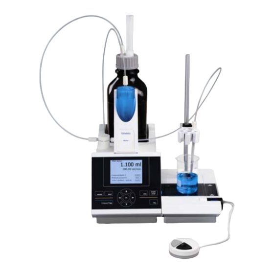
    ® Chapitre 1 - Caractéristiques techniques de la burette à piston TITRONIC ® Caractéristiques techniques de la burette à piston TITRONIC 1.1 Résumé ® La TITRONIC 500 est une burette et appropriée pour les applications suivantes : − Titrage manuel avec ou sans calcul du résultat −...
  • Page 114: Caractéristiques Techniques De La Burette À Piston Titronic ® 500

    : 1200, 2400, 4800, 9600, 19200 (par défaut 4800 bauds) Adresse réglable : (0 à 15, valeur par défaut :01) RS-232-1 pour ordinateur personnel, entrée Daisy Chain  RS-232-2 appareils de SI Analytics, titreur TitroLine 7000,    - burettes à piston TITRONIC 500, TITRONIC...
  • Page 115 ® Chapitre 1 - Caractéristiques techniques de la burette à piston TITRONIC polypropylène Boîtier en matière plastique à revêtement Clavier frontal 15,3 x 45 x 29,6 cm (l x h x p), hauteur avec unité interchangeable Dimensions du boîtier env. 2,3 kg pour l’appareil de base Poids env.
  • Page 116: Notes D'avertissement Et De Sécurité Et De Sécurité

    1.3 Notes d'avertissement et de sécurité et de sécurité ® L’appareil TITRONIC 500 répond à la classe de protection III. Il a été construit et contrôlé conformément à la norme EN 61 010 - 1, partie 1, mesures de protection pour des appareils de mesure électroniques, et a quitté l'usine dans un état impeccable sur le plan de la sécurité...
  • Page 117: Mise En Place Et Mise En Service

    Chapitre 2 – Mise en place et mise en service Mise en place et mise en service 2.1 Déballage et mise en place de la burette à piston La burette à piston et toutes les pièces additionnelles ainsi que les appareils périphériques ont été soumis à un contrôle approfondi de fonctionnement et de stabilité...
  • Page 118: Raccordement Et Installation Du Titreur Et L'agitateur Magnétique Tm 235

    2.3 Raccordement et installation du titreur et l’agitateur magnétique TM 235 Raccorder le câble d’alimentation basse tension TZ 1853 à la prise 12 V, prise "in" (voir aussi la figure 4 panneau arrière, Section 2.4) au dos du titreur. Branchez ensuite l’alimentation dans la prise de courant. Fig.
  • Page 119: Connexions De La Burette À Piston. Combinaison Avec Accessoires Et Autres Appareils

    5) « out » : raccordement de l’agitateur magnétique TM 235 6) Deux interfaces RS232, 4 broches (mini-DIN) : RS1 pour le raccordement à un ordinateur personnel RS2 pour le raccordement à une balance ou à d’autres appareils de SI Analytics (burettes, échangeurs d’échantillon) 2.4.3 Raccordement d’une imprimante...
  • Page 120: Réglage De La Langue Du Pays

    2.5 Réglage de la langue du pays Au départ de l’usine, la langue est réglée sur l’anglais. Après la mise en circuit de la burette à piston et achèvement du cycle de démarrage, le menu principal s’affiche : Fig. 5 Avec <SYS/<F7>...
  • Page 121: Unités Interchangeables Wa

    Chapitre 2 – Mise en place et mise en service 2.6 Unités interchangeables WA Fig. 8 1) TZ 3871 – Tuyau d’aspiration 2) TZ 3872 – Tuyau de raccordement 3) TZ 3873 – Tuyau de dosage sans pointe de dosage ni support ; TZ 3874.
  • Page 122: Montage Et Échange D'une Unité Interchangeable

    2.7 Montage et échange d’une unité interchangeable L’unité de titrage intègre un lecteur RFID et les unités interchangeables intègrent toutes un transpondeur RFID. Les informations suivantes sont enregistrées dans ce transpondeur : • Dimensions de l’unité interchangeable (non modifiable) • ID de l’unité...
  • Page 123: Dépose De L'unité Interchangeable

    Chapitre 2 – Mise en place et mise en service Fig 9.c 2.7.2 Dépose de l’unité interchangeable La dépose de l’unité interchangeable s’effectue en inversant les opérations : • Appuyer sur le bouton noir à gauche et tirer l’unité interchangeable vers l’avant comme représenté à la fig.
  • Page 124 Lors de la première utilisation, il est recommandé d’inscrire ici au moins le nom du réactif utilisé. A cet effet, confirmer la sélection « Réactif » avec <ENTER>, puis taper le nom et éventuellement la concentration (fig. 12). Fig. 12 Confirmer avec <OK>/<ENTER>...
  • Page 125: Premier Remplissage Ou Rinçage De L'unité Interchangeable Complète

    Chapitre 2 – Mise en place et mise en service Fig. 15 2.8 Premier remplissage ou rinçage de l’unité interchangeable complète Effectuer le premier remplissage de l’unité interchangeable avec le programme de rinçage <Rinçage>. A partir du menu principal (fig. 16), Fig.
  • Page 126 Fig. 18 Confirmer la sélection en appuyant sur <ENTER> : Fig. 19 Il est alors possible de sélectionner le nombre de cycles de rinçage (fig. 19). Pour un premier remplissage, rincer au moins deux fois. Il est possible d’interrompre à tout moment le processus de rinçage (fig. 20) en appuyant sur <STOP>...
  • Page 127: Echange Du Cylindre En Verre Et Du Piston En Ptfe

    Chapitre 2 – Mise en place et mise en service 2.9 Echange du cylindre en verre et du piston en PTFE L’échange du cylindre en verre et du piston s’effectue sans outil. Dans certains cas, l’opération nécessite l’utilisation d’un extracteur de piston. •...
  • Page 128 Fig. 22 b Veiller par principe à monter dans l’unité interchangeable uniquement le cylindre de dimensions appropriées car, sinon, le codage mémorisé dans l’unité interchangeable ne coïnciderait plus avec la taille du cylindre. Cela entraînerait des erreurs de dosage. Pour des raisons de précision du dosage et de l’analyse, il est recommandé de toujours remplacer également le piston en PTFE lors du remplacement d’un cylindre en verre défectueux.
  • Page 129: Travailler Avec La Burette À Piston Titronic ® 500

    ® Chapitre 3 - Travailler avec la burette à piston TITRONIC ® Travailler avec la burette à piston TITRONIC 3.1 Clavier frontal A l’exception des entrées alphanumériques (a-z, A-Z, 0-9) et de quelques rares fonctions, l’exécution de toutes les fonctions peut être commandée via le clavier frontal. Sélection des méthodes, rinçage, configuration du système <Mode>: Modification de la méthode actuelle, nouvelle méthode, copie et suppression d’une méthode...
  • Page 130: Dispositif De Pointage

    3.3 Dispositif de pointage Le dispositif de pointage (« souris », fig. 23) est nécessaire pour le titrage manuel. Mais il peut également être utilisé pour le lancement de méthodes de dosage et autres. Fig. 23 Mode Touche noire Touche grise Titrage manuel Lancement du titrage, pas à...
  • Page 131: Structure De Menu

    ® Chapitre 3 - Travailler avec la burette à piston TITRONIC 3.5 Structure de menu Le système comporte 4 menus de sélection : • Menu de départ ou menu principal • Paramètres de méthode • Sélection des méthodes • Configuration du système Après la mise en circuit, l’écran affiche toujours le menu principal.
  • Page 132 Avec <MODE>/F6, on accède au menu de sélection des méthodes (fig. 26). Fig. 26 Sélectionner les méthodes existantes avec <↓> undo <↑> et confirmer sa sélection avec <OK>/<ENTER>. Après la sélection, le système revient aussitôt au menu principal avec la méthode nouvellement sélectionnée. Si aucune méthode n’a été...
  • Page 133: Menu Principal

    ® Chapitre 3 - Travailler avec la burette à piston TITRONIC 3.6 Menu principal Après la mise en circuit, le menu principal s’affiche toujours. La méthode utilisée en dernier lieu est toujours affichée (fig. 29). Dans ce cas, il s’agit d’une méthode de titrage. Fig.
  • Page 134 Fig. 32 Entrer les données de balance au moyen du clavier frontal ou du clavier externe. Confirmer l’entrée avec <OK>/<ENTER>. En cas de reprise automatiques des données de balance, les quantités pesées sont lues dans la mémoire de données de la balance. En l’absence de données de balance dans la mémoire, il y a affichage d’un message indiquant l’absence de données de balance (fig.
  • Page 135: Dosage

    ® Chapitre 3 - Travailler avec la burette à piston TITRONIC Fig. 35 Le degré 5 correspond à la vitesse de titrage maximale. A chaque degré, la vitesse diminue d’environ 50 %. Exemple : unité interchangeable WA 20 : Degré 5 40,00 ml/min Degré...
  • Page 136 Fig. 38 Le volume dosé s’affiche brièvement avant que le menu principal s’affiche à nouveau. Fig. 39 Fig. 40 Il est possible de lancer aussitôt le dosage suivant. L’unité interchangeable n’est pas automatiquement remplie après le dosage, à moins que le volume de cylindre maximal ne soit atteint ou que l’option de remplissage automatique ne soit activée.
  • Page 137: Préparation De Solutions

    ® Chapitre 3 - Travailler avec la burette à piston TITRONIC Le volume est entré et dosé après la confirmation avec <ENTER>/<OK> : Fig. 42 Pour exécuter d’autres dosages, appuyer sur <ENTER>/<OK>. L’unité interchangeable n’est pas automatiquement remplie après le dosage, à moins que le volume de cylindre maximal ne soit atteint. Avec <FILL>, il est possible de remplir l’unité...
  • Page 138 Fig. 45 Si le volume calculé est supérieur au volume maximal réglé, un message d’erreur s’affiche et, pour des raisons de sécurité, le dosage n’est pas effectué : Fig. 46...
  • Page 139: Paramètres De Méthode

    Chapitre 4 - Paramètres de méthode Paramètres de méthode A partir du menu principal (fig. 43/fig. 24), on accède aux paramètres de méthode avec <EDIT>/<F3> : Fig. 47 4.1 Edition d’une méthode et nouvelle méthode En sélectionnant <Editer une méthode> ou <Nouvelle méthode>, on accède au menu permettant de modifier une méthode ou de créer une nouvelle méthode.
  • Page 140: Copie De Méthodes

    Une fois la méthode sélectionnée, le système demande aussitôt l’entrée du nom de méthode (fig. 50). Fig. 50 Il est possible de reprendre le nom standard tel quel ou de le modifier. Ensuite, le système commute sur <Modification des paramètres de méthode>. Continuer au chapitre 4.5. 4.3 Copie de méthodes Il est possible de copier des méthodes et de les enregistrer sous un nouveau nom.
  • Page 141: Modification Des Paramètres De Méthode

    Chapitre 4 - Paramètres de méthode 4.5 Modification des paramètres de méthode L’entrée et la modification du nom de méthode ont déjà été décrites aux chapitres 4.1 et 4.3. Fig. 53 4.5.1 Type de méthode L’option de menu <Type de méthode> permet de sélectionner si l’on désire effectuer un titrage manuel, un dosage ( distribution) ou bien préparer une solution (fig.
  • Page 142: Formules Pour Le Titrage Manuel

    Fig. 56 Confirmer l’entrée avec <OK</<ENTER>. 4.5.2.1 Formules pour le titrage manuel Dans l’option de menu Sélection de la formule, sélectionner la formule de calcul appropriée : Fig. 57 Les formules de calcul suivantes sont disponibles pour le titrage manuel : Formule pour le titrage Remarque (ml--B)*T*M*F1/(W*F2)
  • Page 143: Formules Pour La Préparation De Solutions

    Chapitre 4 - Paramètres de méthode Après sélection d’une formule, confirmer avec <OK>/<ENTER> : Fig. 58 Il est alors possible d’entrer une par une les valeurs des différents paramètres de la formule de calcul sélectionnée : Fig. 59 4.5.2.2 Formules pour la préparation de solutions Des formules de calcul particulières sont disponibles pour le mode Préparation de solutions.
  • Page 144: Quantité Pesée Et Volume D'échantillon (Quantité D'échantillon)

    Signification des différents facteurs : quantité d’échantillon pesée en g part soluble de composants étrangers en % part non soluble de composants étrangers en % facteur de conversion pour unité = 10 mg/l et ppm = 10000 g/100 ml concentration de consigne de la solution à préparer en g/l, mg/l (ppm), g/100 ml, ou en % densité...
  • Page 145: Unité De Formule

    Chapitre 4 - Paramètres de méthode Pour la quantité d’échantillon (W), l’utilisateur choisit s’il désire utiliser une quantité pesée ou un volume d’échantillon pour le titrage ou la préparation de la solution. Les options sont les suivantes (fig. 62) : •...
  • Page 146: Paramètres De Dosage

    4.5.3 Paramètres de dosage Fig. 65 Les paramètres de dosage (vitesse de dosage, vitesse de remplissage et volume maximum de dosage/titrage) sont fixés pour chacune des différentes méthodes. Ceci vaut pour tous les types de méthodes tels que titrage manuel, dosage et préparation de solutions : Fig.
  • Page 147: Désignation De L'échantillon

    Chapitre 4 - Paramètres de méthode Selon l’unité interchangeable, il est possible de régler la vitesse de dosage en % de 1 à 100 %. 100 % = 100 ml/min. Unité interchangeable Vitesse de dosage maximale [ml/min] WA 05 WA 10 WA 20 WA 50 Il est possible de régler la vitesse de remplissage en secondes de 20 à...
  • Page 148: Documentation

    Il sera bientôt possible (nouvel update) de sortir la documentation dans un fichier PDF sur une clé USB raccordée. Veuillez vous renseigner auprès de votre revendeur ou directement auprès de SI Analytics.
  • Page 149: Configuration Du Système

    Chapitre 5 - Configuration du système Configuration du système Fig. 71 Pour accéder à la configuration du système à partir du menu principal (fig. 71), actionner <SYS>/<F7> ou activer <MODE> par les touches du clavier frontal, puis <Configuration du système> : Fig.
  • Page 150 Fig. 73 Fig. 74 Fig. 75 Lorsque l’on quitte le menu <Réactifs WA> avec <ESC>, le système demande toujours si les valeurs doivent être reprises : Fig. 76 En cas de réponse par <Oui>, les valeurs actualisées sont inscrites dans le transpondeur RFID de l’unité interchangeable.
  • Page 151: Réglages Rs232

    Chapitre 5 - Configuration du système 5.2 Réglages RS232 ® Dans le menu <Réglages RS232>, il est possible de déterminer l’adresse de l’appareil de la TITRONIC 500 et de régler séparément les paramètres des deux interfaces RS232 : Fig. 77 L’adresse de l’appareil peut être réglée sur 0 à...
  • Page 152 Fig. 80 La parité peut être réglée sur <No> (sans), <Even> (paire) et <Odd> (impaire). Elle est préréglée sur <No> : Fig. 81 Les bits de données peuvent être réglés entre 7 et 8 bits. Ils sont préréglés sur 8 bits: Fig.
  • Page 153: Date Et Heure

    Chapitre 5 - Configuration du système 5.3 Date et heure Au départ de l’usine, l’heure est réglée sur l’heure de l’Europe centrale. Si besoin, le réglage peut être modifié: Fig. 83 5.4 Mot de passe La fonction ‘Mot de passe’ n’est actuellement pas encore validée. Veuillez demander un update à votre revendeur.
  • Page 154: Informations Sur L'appareil

    5.6 Informations sur l’appareil Les <Informations sur l’appareil> contiennent les informations suivantes : • Version logiciel actuelle • Numéro de série de l’appareil • Pilote d’imprimante et version mise à jour • Adresse d’appareil réglée Fig. 85 En cas de demande de service technique, veuillez tenir ces informations sur l’appareil à disposition. 5.7 Sons du système Ici, il est possible de régler le volume sonore des sons du système et du clavier frontal de l’appareil.
  • Page 155: Mise À Jour Du Logiciel

    Chapitre 5 - Configuration du système 5.8 Mise à jour du logiciel Fig. 87 Mise à jour du logiciel de l’appareil requiert une clé USB sur laquelle est enregistrée la nouvelle version. Les deux fichiers nécessaires doivent se trouver dans le répertoire root de la clé USB : Connecter la clé...
  • Page 156 Fig. 89 Puis il commute quelques secondes après sur l’affichage suivant : Fig. 90 Après mise à jour (env. 1-2 minutes), l’appareil arrête complètement le logiciel et démarre à nouveau. Remarque : Pendant mise à jour, ne pas mettre l’appareil hors tension. Important : Lors de mise à...
  • Page 157: Communication De Données Via L'interface Rs 232 Et Usb-B

    RS232 1. En ce qui concerne le driver de logiciel, veuillez vous mettre en contact avec la société SI Analytics. L’adresse est toujours composée de deux signes : p.ex. l’adresse 1 est composée des deux signes ASCII <0> et <1>.
  • Page 158: Liste D'ordres Pour La Communication Rs

    6.3 Liste d’ordres pour la communication RS Les ordres sont constitués de trois parties : adresse à 2 caractères aa, p.ex. : 01 ordre p.ex. : DA variable, si nécessaire p.ex. : 14 et fin de l’ordre <CR> <LF> Chaque ordre doit se terminer par les signes ASCII <CR> et <LF> (Carriage Return et Line Feed). Toutes les réponses sont renvoyées à...
  • Page 159: Raccordement De Balances D'analyse Et D'imprimantes

    Chapitre 7 – Raccordement d’impremantes Raccordement de balances d’analyse et d’imprimantes 7.1 Raccordement de balances d’analyse Les échantillons étant très fréquemment pesés sur une balance d’analyse, il est rationnel de raccorder cette ® ® balance à la TITRONIC 500. Pour pouvoir raccorder la balance à l’interface RS232 (2) de la TITRONIC 500, la balance doit posséder une interface RS 232 C et il faut disposer d’un câble de raccordement de configuration correspondante.
  • Page 160: Editeur De Balance

    7.2 Editeur de balance Une pression sur la touche de fonction <F5/Symbole de balance> permet d’appeler l’éditeur dit de données de balance. Une liste contenant les données de balance existantes s’affiche : Fig. 92 Il est possible d’éditer séparément les données de balance. Après une modification, une croix s’affiche devant la quantité...
  • Page 161: Raccordement D'imprimantes

    Chapitre 7 – Raccordement d’impremantes Fig. 95 Raccordement d’imprimantes Il est possible d’imprimer les résultats, les données de calibration et les méthodes sur les supports suivants : • Imprimante compatible HP PCL (A4) • Seiko DPU S445 (papier thermique 112 mm de largeur) •...
  • Page 162: Maintenance Et Entretien De La Burette À Piston Titronic ® 500

    ® Maintenance et entretien de la burette à piston TITRONIC Pour conserver sa capacité de fonctionnement à la burette à piston, il faut qu’elle soit l’objet de contrôles et de travaux de maintenance réguliers. La justesse du volume et la capacité de fonctionnement de la burette à piston sont soumises à la condition de contrôles réguliers.
  • Page 163: Stockage Et Transport

    Le contrôle de fiabilité en matière de technique de mesure, travaux de maintenance compris, est proposé par la société SI Analytics GmbH comme prestation de service (sur commande avec certificat de contrôle du fabricant). A cet effet, l’appareil de titrage doit être envoyé à la société SI Analytics GmbH.
  • Page 164: Index

    Index Affichage 129 Montage et raccordement de l’agitateur balances d’analyse 119 magnétique 118 Clavier frontal 129 Mot de passe 153 Clavier PC externe 130 notes d'avertissement 116 clé USB 119 Nouvelle méthode 139 Configuration du système 149 Paramètres de dosage 146 Copie de méthodes 140 Paramètres de méthode 139 Désignation de l’échantillon 147...
  • Page 165 TABLA DE MATERIAS PAGINA ® Propiedades técnicas de la Bureta de émbolo TITRONIC 500 ......167 Resumen ..........................167 ® Propiedades técnicas de la Bureta de émbolo TITRONIC 500 ........... 168 instrucciones de seguridad y advertencias ................169 Montaje y puesta en marcha ................. 171 Desempaque y montaje de la bureta de émbolo ..............
  • Page 166 Transmisión de datos mediante las interfaces RS-232- y USB-B ...... 211 Generalmente ........................211 Conexión en cadena de varios equipos — „Sistema Daisy Chain “ ........211 Lista de mandos para comunicación RS................212 Conexión de balanzas analíticas e impresoras ........... 213 Conexión de balanzas analíticas ..................
  • Page 167: Propiedades Técnicas De La Bureta De Émbolo Titronic ® 500

    ® Capítulo 1 - Propiedades técnicas de la bureta de émbolo TITRONIC ® Propiedades técnicas de la Bureta de émbolo TITRONIC 1.1 Resumen ® La TITRONIC 500 es una bureta y apta para los siguientes usos: − Titulaciones manuales con o sin cálculo de resultados −...
  • Page 168 1200, 2400, 4800, 9600, 19200 (Default 4800 Baud) Dirección: ajustable, (0 a 15, Default:01) RS-232-1 para ordenador, entrada Daisy Chain  RS-232-2 aparatos de SI Analytics, titulador TitroLine 7000,    - Buretas de émbolo TITRONIC 500, TITRONIC...
  • Page 169: Instrucciones De Seguridad Y Advertencias

    ® Capítulo 1 - Propiedades técnicas de la bureta de émbolo TITRONIC Estado 21.11.2013 Material de la caja: Polipropileno Teclado frontal: Con recubrimiento de plástico. Dimensiones de la caja: 15,3 x 45 x 29,6 cm (b x h x t), Altura con unidad cambiable Peso: aparato básico aprox.
  • Page 170 ® Capítulo 1 - Propiedades técnicas de la bureta de émbolo TITRONIC ® En caso de no respetar las advertencias la Bureta de émbolo TITRONIC 500 puede resultar peligroso: puede causar daños por accidentes eléctricos o riesgo de incendio. En caso de anipulación ®...
  • Page 171: Montaje Y Puesta En Marcha

    Capítulo 2 - Montaje y puesta en marcha Montaje y puesta en marcha 2.1 Desempaque y montaje de la bureta de émbolo La bureta de émbolo, todos sus accesorios y los aparatos periféricos han sido revisados cuidadosamente en fábrica respecto a su funcionamiento y a su exactitud dimensional. Por favor verifique que también los accesorios pequeños hayan sido totalmente desempacados.
  • Page 172: Conexión E Instalación Del Titulador Y El Agitador Magnético Tm 235

    Capítulo 2 - Montaje y puesta en marcha 2.3 Conexión e instalación del titulador y el agitador magnético TM 235 El cable de bajo voltaje de la fuente de poder TZ 1853 debe ser conectado en la toma de 12 V „in“, (ver Fig. 4 panel trasero, capítulo.
  • Page 173: Tomas De La Bureta De Émbolo. Combinación Con Accesorios Y Otros Aparatos

    5) „out“: Conexión del agitador magnético TM 235 6) Dos interfaces RS232, 4 polos (Mini-DIN): RS1 para conexión a un PC RS2 para conectar una balanza y otros aparatos de SI Analytics (buretas, cambiadores de muestras) 2.4.3 Conexión de una impresora Las impresoras con interface USB se conectan a una de las interfaces USB-A.
  • Page 174: Ajustes De Idioma

    Capítulo 2 - Montaje y puesta en marcha 2.5 Ajustes de idioma El idioma programado en fábrica es inglés. Una vez conectada a la corriente la bureta de émbolo y terminado el proceso de iniciación aparece el menú principal. Fig. 5 Con <SYS/<F7>...
  • Page 175: Unidad Cambiable Wa

    Capítulo 2 - Montaje y puesta en marcha 2.6 Unidad cambiable WA Fig. 8 1) TZ 3871 - Tubo flexible de succión 2) TZ 3872 - Tubo flexible de conexión 3) TZ 3873 - Tubo flexible de dosificación sin punta de succión ni soporte; TZ 3874.- Tubo flexible de dosificación con punta de succión y soporte 4) TZ 3801 - Tapa de la válvula 5) TZ 3000 - Válvula de 3/2 pasos...
  • Page 176: Colocación Y Cambio De Una Unidad Cambiable

    Capítulo 2 - Montaje y puesta en marcha 2.7 Colocación y cambio de una unidad cambiable La unidad de titulación contiene un lectorf RFID y las piezas cambiables tienen un retransmisor RFID. En este retransmisor pueden guardarse las siguientes informaciones: •...
  • Page 177: Retirar Una Unidad Cambiable

    Capítulo 2 - Montaje y puesta en marcha Fig. 9.c 2.7.2 Retirar una unidad cambiable El retiro de la unidad cambiable se realiza en el orden contrario. • Se presiona el botón negro a la izquierda y se hala hacia adelante la unidad cambiable, como se muestra en la Fig.
  • Page 178 Capítulo 2 - Montaje y puesta en marcha Al utilizarlo la primera vez se aconseja introducir aquí al menos el nombre del reactivo utilizado. Para ello se confirma con <ENTER> la selección de " reactivo “ luego se introduce el nombre y eventualmente la concentración.
  • Page 179: Primer Llenado. Y/O Enjuague De La Unidad Cambiable Completa

    Capítulo 2 - Montaje y puesta en marcha Fig. 15 2.8 Primer llenado. y/o enjuague de la unidad cambiable completa El primer llenado de la unidad cambiable se realiza mediante el programa de enjuague <enjuague>. Partiendo del menú principal (Fig. 16). Fig.
  • Page 180 Capítulo 2 - Montaje y puesta en marcha Fig. 18 La selección se confirma con <ENTER>. Fig. 19 Ahora puede seleccionarse el número de ciclos de enjuague (Fig. 19). Para el primer llenado se debe juagar por lo menos dos veces.. El proceso de enjuague (Fig. 20) se puede interrumpir en cualquier momento con <STOP> y luego continuarlo con <START>.
  • Page 181: Cambio Del Cilindro De Vidrio Y Del Émbolo De Ptfe

    Capítulo 2 - Montaje y puesta en marcha 2.9 Cambio del cilindro de vidrio y del émbolo de PTFE El cambio del cilindro de vidrio y del émbolo no requiere herramienta adicional alguna. En casos aislados es necesario utilizar el extractor del émbolo. •...
  • Page 182 Capítulo 2 - Montaje y puesta en marcha Fig. 22 b En principio debe considerarse, que en una unidad cambiable solamente se pueden montar cilindros del tamañoo para ella previsto ya que de lo contrario la codificación memorizada en la unidad cambiable no concordaría con el tamaño del cilindro, teniendo como consecuencia una dosificación errada.
  • Page 183: Trabajo Con La Bureta De Émbolo Titronic ® 500

    ® Capítulo 3 - Trabajo con la bureta de émboloTITRONIC ® Trabajo con la bureta de émbolo TITRONIC 3.1 Teclado frontal Todas las funciones, con excepción de la introducción de datos alfanuméricos (a-z, A-Z, 0-9) y de unas pocas funciones, pueden realizarse también utilizando el teclado frontal. <Mode>: Elección del método, enjuague, ajustes del sistema <EDIT>:...
  • Page 184: Mando Manual

    ® Capítulo 3 - Trabajo con la bureta de émboloTITRONIC 3.3 Mando manual El mando manual ("ratón“, Fig. 23) se necesita en el proceso de titulación manual y puede utilizarse también para iniciar la dosificación y otros métodos. Fig. 23 Modo Botón negro Botón gris...
  • Page 185: Estructura Del Menú

    ® Capítulo 3 - Trabajo con la bureta de émboloTITRONIC 3.5 Estructura del menú Hay cuatro menús para elegir: • Menú de inicio o menú principal • Parámetros de los métodos, • Métodos disponibles para selección • Ajustes del sistema. Cuando se prende el equipo aparece siempre el menú...
  • Page 186 ® Capítulo 3 - Trabajo con la bureta de émboloTITRONIC Con <MODE>/F6 se llega al menú para la selección del método. (Fig. 26). Fig. 26 Los métodos disponoibles se seleccionan mediante las teclas <↓> y <↑> y la selección se confirma con <OK>/<ENTER>.
  • Page 187: Menú Principal

    ® Capítulo 3 - Trabajo con la bureta de émboloTITRONIC 3.6 Menú principal Al prender el equipo aparece siempre el menú principal.y el display muestra siempre el último método utilizado. (Fig. 29). En este caso un método de titulación (HCl). Fig.
  • Page 188 ® Capítulo 3 - Trabajo con la bureta de émboloTITRONIC Fig. 32 Los datos de peso pueden introducirse con el teclado frontal o con el teclado externo. Los dataos intoducidos se confirman con <OK>/<ENTER>. Si se asumen automáticamaente los datos de la balanza, los datos se extraen de la memoria de la balanza. Si no hay datos guardados en la balanza, aparece una nota anunciando que no hay datos en ella.
  • Page 189 ® Capítulo 3 - Trabajo con la bureta de émboloTITRONIC Fig. 35 El nivel 5 corresponde a la máxima velocidad de titulación. La velocidad se reduce cada vez en un 50% aprox. Ejemplo.: Unidad cambiable WA 20: Nivel 5 40,00 ml/min Nivel 4 20,00 ml/min Nivel 3...
  • Page 190 ® Capítulo 3 - Trabajo con la bureta de émboloTITRONIC Fig. 38 Por un corto momento, antes de devolverse al menú principal, aparece en el display el volumen dosificado. Fig. 39 Fig. 40 Entonces puede inmediatamente iniciarse la dosificación siguiente. La unidad cambiable no se llena automáticamente después de la dosificación, a no ser que se haya alcanzado el máximo volumen del cilindro o que se haya activado la función de llenado automático.
  • Page 191 ® Capítulo 3 - Trabajo con la bureta de émboloTITRONIC Se introduce el volumen y después de confirmarlo con <ENTER>/<OK> se dosifica: Fig. 42 Con <ENTER>/<OK> pueden reaslizarse otras dosificaciones. La unidad cambiable no se llena automáticamente después de la dosificación, a no ser que se haya alcanzado el máximo volumen del cilindro. La unidad cambiable puede llenarse en cualquier momento con <FILL>.
  • Page 192 ® Capítulo 3 - Trabajo con la bureta de émboloTITRONIC Fig. 45 Si el volumen calculado es mayor que el volúmen máximo programado, aparece un aviso de eroor y por razones de seguridad no se realiza la dosificación. Fig. 46...
  • Page 193: Parámetros De Los Métodos

    Capítulo 4 - Parámetros de los métodos Parámetros de los métodos Partiendo del menú principal (Fig. 43/Fig. 24) llegamos con <EDIT>/<F3> a los parámetros de los métodos. Fig. 47 4.1 Edición de métodos y método nuevo Al seleccionar "editar método" o "nuevo método" se llega al menú para modificación y/o creación de un nuevo método.
  • Page 194: Copiar Métodos

    Capítulo 4 - Parámetros de los métodos Después de la selección se solicita la introducción del nombre del método (Fig. 50). Fig. 50 Se puede asumir el nombre estándar o cambiar el nombre. A continuación se llega al menú (modificar parámetros del método).
  • Page 195: Modificar Parámetros Del Método

    Capítulo 4 - Parámetros de los métodos 4.5 Modificar parámetros del método La introducción de un nombre de método o su modificación se explicó ya en los Capítulos 4.1 und 4.3.. Fig. 53 4.5.1 Tipo de método En el submenú (tipo de método) se selecciona si se desea realizar una titulación manual o una dosificación, o si se desea prepar una solución.
  • Page 196 Capítulo 4 - Parámetros de los métodos Fig. 56 Su introducción se confirma con <OK</<ENTER>. 4.5.2.1 Fórmulas para titulación manual En el submenú Selección de la fórmula se seleciona la fórmula de cálculo apropiada: Fig. 57 Para la titulación manual están disponibles las siguientes fórmulas: Fórmula para titulación Observaciones (ml-B)*T*M*F1/(W*F2)
  • Page 197 Capítulo 4 - Parámetros de los métodos Cuando se haya seleccionado una fórmula, se confirma su selección con <OK>/<ENTER>: Fig. 58 Los valores de los parámetros individuales de la fórmula de cálculo seleccionada pueden introducirse uno por uno. Fig. 59 4.5.2.2 Fórmulas para la preparación de soluciones Para el modo "prepapración de soluciones"...
  • Page 198 Capítulo 4 - Parámetros de los métodos Significado de los diversoss factores: pesada de la muestra en g componente extraño soluble en % componente extraño insoluble en % factor de conversión para la unidad = 10 mg/l und ppm = 10000 g/100 ml Concentración prevista de la solución a preparar en g/l, mg/l (ppm), g/100 ml, o en % Densidad de la muestra pesada en g/cm³...
  • Page 199 Capítulo 4 - Parámetros de los métodos Bajo cantidad de muestra (W) se selecciona, si en la titulación o en la preparación de la solución se desea utilizar una pesada o un volumen. Es gibt folgende Optionen (Fig. 62): • Pesada manual: Al iniciar el método se solicita la pesada, la que se introduce manualmente.
  • Page 200: Parámetros De Dosificación

    Capítulo 4 - Parámetros de los métodos 4.5.3 Parámetros de dosificación Fig. 65 Los parámetros de dosificación (velocidad de dosificación, velocidad de llenado y volumen máximo de dosificación/de titulación máximo de dosificación/de titulación) se fijan para cada método en particular. Esto vale para todos los tipos de métodos como titulación manual, dosificación y preparación de soluciones.
  • Page 201: Denominación De La Muestra

    Capítulo 4 - Parámetros de los métodos La velocidad de dosificación en ml/min puede fijarse, dependiendo de la unidad cambiable utilizada, entre 1 y 100 %. 100 % = 100 ml/min. Unidad cambiable Velocidad máxima de dosificación [ml/min] WA 05 WA 10 WA 20 WA 50...
  • Page 202: Documentación

    Dentro de poco, con una actualización (update) podrá obtenerse la documentación en un archivo PDF en una memoroia USB debidamente conectada. Por favor póngase en contacto con su distribuidor o contacte directamente SI Analytics.
  • Page 203: Ajustes Del Sistema

    Capítulo 5 - Ajustes del sistema Ajustes del sistema Fig. 71 Partiendo del menú principal (Fig. 71) <SYS>/<F7>o utilizando los botones frontales <MODE> y luego (ajustes del sistema) se llega a los ajustes del sistema.: Fig. 72 El ajuste del idioma se explicó ya en el Capítulo 2.5. 5.1 Unidad cambiable para reactivos Todas las unidades cambiables tienen un retransmisor RFID.
  • Page 204 Capítulo 5 - Ajustes del sistema Fig. 73 Fig. 74 Fig. 75 Al abandonar el menú (reactivos WA) con <ESC> aparece la pregunta, si se desea asumir los valores: Fig. 76 Si se contesta (sí) se guardan los valores actualizados en el retransmisor RFID de la unidad cambiable.
  • Page 205: Ajustes Rs232

    Capítulo 5 - Ajustes del sistema 5.2 Ajustes RS232 ® En el menú (ajustes RS232) se puede fijar la dirección del equipo TITRONIC 500 y además ajustar por separado los parámetros de las dos interfaces RS232. Fig. 77 La dirección del equipo puede ajustarse de 0 a 15. La dirección prefijada es 1. Fig.
  • Page 206 Capítulo 5 - Ajustes del sistema Fig. 80 La paridad puede ajustarse en <No> (ninguna), <Even> (par) und <Odd> (impar). <No>es el ajuste prefijado: Fig. 81 Los bits de datos pueden ajustarse entre 7 y 8. El valor prefijado es de 8 bits: Fig.
  • Page 207: Fecha Y Hora

    Capítulo 5 - Ajustes del sistema 5.3 Fecha y hora En fábrica ha sido prefijada la hora de Europa Central (MEZ). De ser necesario puede modificarse. Fig. 83 5.4 Password La función (password) no es utilizable actualmente. Por favor infóromese con su vendedor sobre una actualización (update).
  • Page 208: Informaciones Sobre El Equipo

    Capítulo 5 - Ajustes del sistema 5.6 Informaciones sobre el equipo En (informaciones sobre el equipo) encuentra usted informaciones sobre • la versión actual del Software • número de serie del aparato • "driver" de la impresora y versión de la actualización (update) •...
  • Page 209: Actualización (Update) Del Sistema

    Capítulo 5 - Ajustes del sistema 5.8 Actualización (update) del sistema Fig. 87 Para la actualización (update) del software del equipo se requiere una memoria USB con la nueva versión. Para ello los dos archivos necesarios deben encontrarse en la lista ROOT de la memoria USB.: Se conecta la memoria USB a un puerto USB-A libre, se esperan un par de segundos y luego se selecciona la función (actualización del software).
  • Page 210 Capítulo 5 - Ajustes del sistema Fig. 89 la que después de pocos segundos cambia así : Fig. 90 Después de la actualización (aprox. 1-2 minutos) el equipo se apaga completamente y se reinicia.. Advertencia: No se debe apagar el equipo durante la actualización. Importante: La actualización no elimina los métodos.
  • Page 211: Transmisión De Datos Mediante Las Interfaces Rs-232- Y Usb-B

    RS232-1. Con respecto al driver para el software póngase en contacto con la empresa SI Analytics. La dirección consta siempre de dos caracteres: p.ej. la dirección 1 consta de los caracteres ASCII <0> y <1>.
  • Page 212: Lista De Mandos Para Comunicación Rs

    Capítulo 6 - Transmisión de datos mediante las interfaces RS-232- y USB-B 6.3 Lista de mandos para comunicación RS Los mandos constan de tres partes: dirección dos caracteres aa, p.ej.: 01 mando p.ej.: DA variable,si es necesario p.ej.: 14 finalización del mando <CR>...
  • Page 213: Conexión De Balanzas Analíticas E Impresoras

    Capítulo 7 - Conexion de balanzas analíticas e impresoras Conexión de balanzas analíticas e impresoras 7.1 Conexión de balanzas analíticas Como la muestra con frecuencia se pesa sobre una balanza anlítica, es conveniente conectar la balanza a la ® ® TITRONIC 500.
  • Page 214: Editor De Datos De La Balanza

    Capítulo 7 - Conexion de balanzas analíticas e impresoras 7.2 Editor de datos de la balanza Presionando la tecla de función <F5/Símbolo de balanza> se pasa al llamado editor de datos de la balanza y aparece una lista con los datos de la balanza disponibles: Fig.
  • Page 215: Conexión De Impresoras

    Capítulo 7 - Conexion de balanzas analíticas e impresoras Fig. 95 Conexión de impresoras Los resultados, datos de calibrado y métodos pueden imprimirse con los siguientes medios de impresión: • Impresoras compatibles con HP PCL (A4) • Seiko DPU S445 (papel térmico de 112 mm de ancho) •...
  • Page 216: Mantenimiento Y Cuidado De La Bureta De Émbolo Titronic ® 500

    Kapitel 8 Lagerung und Transport Kapitel 7 Wartung und Pflege des Titrators Kapitel 7 Wartung und Pflege des Titrators Capítulo 10 - Reciclaje y Eliminación ® 8 Mantenimiento y cuidado de la bureta de émbolo TITRONIC Para mantener la funcionabilidad de la bureta de émbolo deben realizarse regularmente trabajos de control y mantenimiento.
  • Page 217: Almacenaje Y Transporte

    El control de la fiabilidad desde el punto de vista técnico de medición, incluyendo los trabajos de mantenimiento, lo ofrece SI Analytics GmbH como servicio al cliente (si así se solicita, con certificado de control del fabricante). En este caso el titulador debe enviarse a SI Analytics GmbH.
  • Page 218: Index

    Kapitel 8 Lagerung und Transport Kapitel 11 - Index Kapitel 7 Wartung und Pflege des Titrators Kapitel 7 Wartung und Pflege des Titrators Index Actualización (update) del sistema 209 Menú principal 187 Ajustes del sistema 203 Métodos estándar 193 Ajustes RS232 205 Modificar parámetros del método 195 Almacenaje 217 Montaje 171...
  • Page 220 SI Analytics GmbH Hattenbergstr. 10 Tel. +49.(0)6131.66.5111 Fax. +49(0)6131.66.5001 55122 Mainz Deutschland, Germany, Allemagne, Alemania E-Mail: support.si-analytics@xyleminc.com www.si-analytics.com SI Analytics is a trademark of Xylem Inc. or one of its subsidiaries. © 2013 Xylem, Inc. Version 131126 M EDV 8272307...

Table des Matières