Table des Matières

Publicité

Les langues disponibles
  • FR

Les langues disponibles

  • FRANÇAIS, page 33

Liens rapides

Bedieningshandleiding en
installatieinstructies
Operation manual and
installation instructions
Bedienungshandbuch und
Einbauanleitung
Manuel d'utilisation et
instructions d'installation
Manual de manejo y
instrucciones de instalación
Manuale per l'uso e
istruzioni per l'installazione
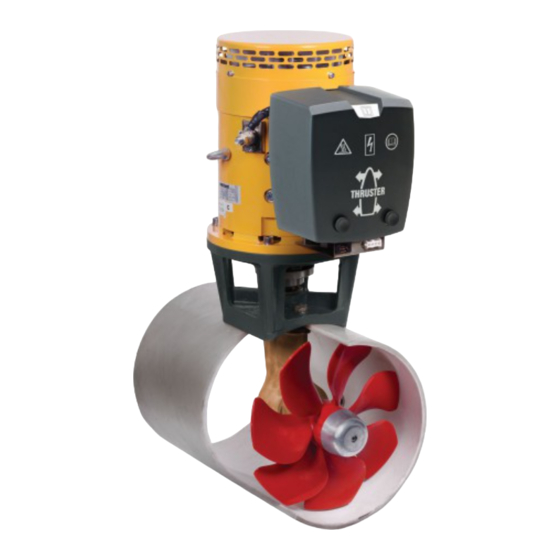
285 kgf
ø 300 mm
Co p yrigh t © 2 00 7 Vetu s d en O ud e n n . v. Sc h i e da m H o l l a n d

Publicité

Table des Matières
loading

Sommaire des Matières pour Vetus BOW28548

  • Page 1 Bedieningshandleiding en installatieinstructies Operation manual and installation instructions Bedienungshandbuch und Einbauanleitung Manuel d’utilisation et instructions d’installation Manual de manejo y instrucciones de instalación Manuale per l’uso e istruzioni per l’installazione 285 kgf ø 300 mm Co p yrigh t © 2 00 7 Vetu s d en O ud e n n . v. Sc h i e da m H o l l a n d...
  • Page 2: Table Des Matières

    Inhoud Contents Inleiding Introduction Veiligheid Safety Gebruik Installatieinstructies Installation instructions Installatie aanbevelingen Installation recommendations Inbouw Installation Stroomverzorging The power supply Elektrische installatie Electrical installation Onderhoud Maintenance Storingen Trouble shooting Technische gegevens Technical data Inbouwvoorbeelden Installation examples Elektrisch schema Wiring diagram Hoofdafmetingen Principal dimensions Inhalt...
  • Page 3: Inleiding

      NEDERLANDS Inleiding Veiligheid Afhankelijk van de windvang, de waterverplaatsing en de vorm van het onderwaterschip zal de door de boegschroef geleverde WAARSCHUWING! stuwkracht op ieder schip een verschillend resultaat geven. Let bij het gebruik van de boegschroef op het gevaar voor zwemmers of lichte bootjes welke zich in de onmiddelijke De nominaal opgegeven stuwkracht is alleen haalbaar onder nabijheid van de boegschroefbuis-uitstroomopeningen...
  • Page 4: Installatieinstructies

    Wij raden de installatie van 2 boegschroeven in één (1) tunnel- buis af; er wordt geen verdubbeling van de stuwkracht bereikt! Deze installatie instructie geeft richtlijnen voor de inbouw van de Vetus boegschroef ‘BOW28548’. Bij het kiezen van de positie waar de tunnel-...
  • Page 5: Overgang Van Tunnelbuis Naar Scheepsromp

      NEDERLANDS Overgang van tunnelbuis naar scheepsromp Indien de overgang van tunnel- buis op scheepsromp met een schuine zijde wordt uitgevoerd De wijze waarop de tunnelbuis overgaat in de scheeps- dient deze volgens de tekening romp is van grote invloed op de door de boegschroef te worden uitgevoerd.
  • Page 6: Inbouw

    Bij een stalen of aluminium tunnelbuis kan vermindering Polyester tunnelbuis: van corrosie worden bereikt Hars: Het voor de polyester tunnelbuis toegepaste hars is door het volledig geïsoleerd isophtaalzure polyesterhars (Norpol PI 2857). opstellen van het staartstuk Voorbehandeling: De buitenzijde van de buis moet wor- in de tunnelbuis.
  • Page 7: Montage Staartstuk En Tussenflens

      NEDERLANDS Montage staartstuk en tussenflens Eindmontage H = 49 - 54 mm Breng één pakking aan tus- sen staartstuk en tunnelbuis, Controleer nu nogmaals pas hierbij -tussen staartstuk maat ‘H’! en pakking- een afdichtmid- del (polyurethaan* of silico- nen) toe, en plaats het staart- stuk in het gat in de tunnel- buis.
  • Page 8: Stroomverzorging

    ‘Installatieinstructies’. Bij toe- schroef zijn afgestemd, zie tabel. passing van aanzienlijke grotere accu’s in combinatie Wij bevelen Vetus onderhoudsvrije scheepsaccu’s aan; welke met zeer korte accuaansluitkabels met een aanzienlijke leverbaar zijn in de navolgende grootten : 55 Ah, 70 Ah, 108 Ah, grotere doorsnede dan aanbevolen zal de stuwkracht 120 Ah, 143 Ah, 165 Ah, 200 Ah en 225 Ah.
  • Page 9: Elektrische Installatie

      NEDERLANDS Electrische installatie Let op dat bij het aansluiten van elektrische kabels Indien twee stuurstanden aanwezig zijn kan het tweede paneel geen andere elektrische delen los komen. op het eerste paneel worden aangesloten. Controleer na 14 dagen alle elektrische verbindingen. Ten gevolge van temperatuurschommelingen kunnen elektrische delen (bijvoorbeeld bouten en moeren) los komen.
  • Page 10: Onderhoud

    Art. code V- ring: BP1055. Voor accu-onderhoud dienen de instructies van de acculeveran- cier te worden geraadpleegd. VETUS accu’s zijn onderhouds- vrij. 020569.01 Bedieningshandleiding en installatieinstructies Boegschroef 285 kgf, ø 300 mm...
  • Page 11: Storingen

    ) Boegschroef Zekering: ‘traag’ Art. code BOW28548 (48 V) 355 A ZE 355 Bedieningshandleiding en installatieinstructies Boegschroef 285 kgf, ø 300 mm 020569.01...
  • Page 12: Technische Gegevens

    Technische gegevens Type BOW28548 Electromotor Type omkeerbare gelijkstroommotor Spanning 48 V = Stroom 560 A Afgegeven vermogen 16 kW Toerental 2000 omw/min Inschakelduur S2 - 3 min. Bescherming IP21 Motoren zijn conform CE (89/336/EEC, EMC - EN60945) Transmissie Tandwielen Conisch, rechte tanden...
  • Page 13       ENGLISH Introduction Safety The thrust given by the bow thruster will vary from vessel to ves- sel depending on the effect of the wind, the water displacement WARNING! and the shape of the underwater hull. When using the bow thruster watch out for swimmers or light boats which could be in the near vicinity of the bow The nominal thrust quoted can only be achieved under the most thruster tunnel jet openings.
  • Page 14: Installation Instructions

    When choosing the location for the thrust tunnel, take the follow- These installation instructions give guidelines for fitting the ing into account for Vetus bow thruster ‘BOW28548’. optimum performance: • The distance The standard of fitting determines the reliability of the bow shown in the draw- thruster.
  • Page 15: Connection Of Thrust Tunnel To Ship's Hull

          ENGLISH Connection of thrust tunnel to ship’s hull If the connection of the thrust tunnel and the ship’s hull is to be made with a sloped side, it should be executed in accord- The manner, in which the thrust tunnel is connected to the ance with the drawing.
  • Page 16: Installation Of The Thrust Tunnel

    Corrosion of a steel or alu- minium thrust tunnel can be Polyester thrust tunnel: reduced by ensuring that the Resin: The resin used for the polyester thrust tunnel is tail piece is completely insu- Isophtalic polyester resin (Norpol Pl 2857). lated from the thrust-tunnel.
  • Page 17: Final Assembly

          ENGLISH Installation of tail piece and intermediate Final assembly H = 49 - 54 mm (1.93”-2.13”) flange Check again dimension ‘H’. Install one (1) gasket between the tail piece and the thrust tunnel. Apply a sealant (poly- ure-thane* or silicon) between the tail piece and the gasket Make sure that the key 1 is...
  • Page 18: The Power Supply

    A main switch and fuse must be fitted in the ‘plus’ cable. A Vetus battery switch is suitable here. The fuse protects the bow thruster against overvoltage and at the same time protects the vessel’s wiring against short-circuits.
  • Page 19: Electrical Installation

          ENGLISH Electrical installation Make sure that no other electrical parts come loose If there are two steering positions, the second control panel can when connecting the electric cables. be connected to the first one. Check all electrical connections after 14 days. Electrical parts (such as bolts and nuts) may come loose as a result of fluctuations in temperature.
  • Page 20 V-ring, article code: BP1055. The instructions of the manufacturer should be followed for the maintenance of the batteries. Vetus batteries are maintenance free. 020569.01 Operation manual and installation instructions Bow thruster 285 kgf, ø 300 mm...
  • Page 21 ) Bow thruster Fuse: ‘slow blow’ Art. code BOW28548 (48 V) 355 A ZE 355 Operation manual and installation instructions Bow thruster 285 kgf, ø 300 mm 020569.01...
  • Page 22: Technical Data

    Technical data Type BOW28548 Electric motor Type reversible DC motor Voltage 48 V DC Current 560 A Rated output 16 kW No. of revolutions 2000 rpm Rating S2 - 3 min. Protection IP21 Motors conform to CE (80/336/EEC, EMC - EN60945)
  • Page 23: Einleitung

          DEUTSCH Einleitung Sicherheitsbestimmungen Je nach Takelage, Wasserverdrängung und Unterwasser- schifform führt die Antriebskraft durch die Bugschraube auf WARNUNG! jedem Schiff zu anderen Ergebnissen. Achten Sie bei Benutzung der Bugschraube auf die Gefahr für Schwimmer und kleine Boote, die sich in unmit- Die angegebene Nennantriebskraft ist nur unter optimalen telbarer Nähe der Bugschraubenrohrausström-öffnungen Umständen erreichbar:...
  • Page 24: Einbauanleitung

    Wir raten davon ab, 2 Bugschrauben in einem (1) Tunnelrohr einzu-bauen. Eine Verdoppelung der Antriebskraft wird dadurch nicht erreicht! Diese Einbauanleitung enthält Richtlinien für den Einbau der Vetus Bugschraube ‘BOW28548’. Bei der Platzbestimmung Tunnelrohrs soll Die Einbauqualität ist maßgeblich für die Zuverlässigkeit der für die bestmöglichen...
  • Page 25: Übergang Vom Tunnelrohr Zum Schiffsrumpf

          DEUTSCH Übergang vom tunnelrohr zum schiffsrumpf Wenn Übergang Tunnelrohr zum Schiffsrumpf mit abgeschrägter Seite versehen wird, so soll die Ausführung laut Die Art und Weise worauf das Tunnelrohr zum Schiffsrumpf obenstehender Zeichnung durch- übergeht, beeinflusst sehr den von der Bugschraube geführt werden.
  • Page 26: Einbau

    Korrosion eines Stahl- oder Aluminium-Tunnelrohrs kann Polyester-Tunnelrohr: verringert werden durch voll- Harz: Für das Polyester-Tunnelrohr wird isophtal-saures ständig isolierte Montage Polyesterharz (Norpol PI 2857) benutzt. des Unterwasserteils in das Vorbehandlung: Die Außenseite der Rohre ist aufzurau- Tunnelrohr. hen. Die gesamte, obere Schicht bis zum Glasfibergewebe ACHTUNG: Die mitgeliefer- entfernen, dafür eine Schleifscheibe benutzen.
  • Page 27: Befestigung Des Unterwasserteils Und Des Zwischenflansches

          DEUTSCH Befestigung des Unterwasserteils und des Endmontage H = 49 - 54 mm Zwischenflansches Zwischen Unterwasserteil Wiederum das Mass ‘H’ prü- und Tunnelrohr eine (1) fen. Dichtung anbringen dabei - zwischen dem Unter- wasserteil und der Dichtung - eine Dichtungsmasse (Poly- urethan* oder Silikon) ver- Prüfen Sie daß...
  • Page 28: Stromversorgung

    Akkuanschlußkabeln. Siehe Einbauanleitungen. Bei Bugschraube abgestimmt sein. Siehe Tabelle. Verwendung erheblich größerer Akkus in Kombination Wir empfehlen wartungsfreie Schiffsakkus von Vetus. Sie sind mit sehr kurzen Akkuanschlußkabeln mit einem erheb- in folgenden Größen lieferbar: 55 Ah, 70 Ah, 108 Ah, 120 Ah, lich größeren Durchschnitt als empfohlen nimmt die...
  • Page 29: Elektrische Installation

          DEUTSCH Elektrische Installation Achten Sie darauf, dass sich beim Anschluss von Wenn zwei Steuerstände vorhanden sind, kann das zweite Elektrokabeln keine anderen elektrischen Teile lösen. Armaturenbrett am ersten angeschlossen werden. Kontrollieren Sie nach 14 Tagen alle elektrischen Verbindungen.
  • Page 30: Wartung

    Einen neuen V-Ring einsetzen. Den Achsnagel wieder auf die Achse setzen und die Schraube wieder einbauen. Art.-Nr. V-Ring: BP1055. Bei der Akku-Wartung sind die Anweisungen des Akkulieferanten zu beachten. VETUS Akkus sind wartungsfrei. 020569.01 Bedienungshandbuch und Einbauanleitung Bugschraube 285 kgf, ø 300 mm...
  • Page 31: Störungen

    Steuerstromsicherung entweder am Bugschraubenmotor oder Armaturenbrett. Auch kann sich sowohl am Bugschraubenmotor als im Armaturenbrett eine Steuerstromsicherung befinden. ) Bugschraube Sicherung: ‘träge’ Artikelnummer BOW28548 (48 V) 355 A ZE 355 Bedienungshandbuch und Einbauanleitung Bugschraube 285 kgf, ø 300 mm 020569.01...
  • Page 32: Technische Daten

    Technische daten BOW28548 Electromotor umkehrbarer Gleichstrommotor Spannung 48 V = Strom 560 A Leistung 16 kW Drehzahl 2000 U/min Einschaltdauer S2 - 3 min. Sicherung IP21 Motoren sind CE-konform (80/336/EEC, EMC - EN60945) Übertragung Zahnräder Geradzahne, Kegelräder Übersetzung 1,39 : 1 Schmierung Ölbad, ca.
  • Page 33       FRANÇAIS Introduction Sécurité Selon la prise de vent, le déplacement d’eau et la forme des oeuvres vives, la force de propulsion fournie par l’hélice d’étra- AVERTISSEMENT! ve entraînera un résultat différent sur chaque bateau. Lorsque vous utilisez l’hélice d’étrave, assurez-vous qu’il n’y a pas de nageurs ou de petits bateaux légers au voisi- La force de propulsion nominale indiquée n’est réalisable que nage immédiat des ouvertures de sortie du tube d’hélice...
  • Page 34: Recommandations D'installation

    ; on n’obtiendra pas une force de propul- sion double ! Les présentes instructions d’installation fournissent les directi- ves de montage pour l’hélice d’étrave Vetus ‘BOW28548’. Afin d’obtenir les meilleurs résultats, il faut observer La qualité du montage est déterminante pour la fiabilité de ce qui suit, a la détermi-...
  • Page 36 Boormal Drill pattern Bohrschablone Gabarit Plantilla de perforación Dima di foratura 020569.01...
  • Page 37 Schaal 1:1 Scale 1:1 Maßstab 1:1 285 kgf ø 300 mm Echelle 1:1 Escala 1:1 Scala 1:1 FOKKERSTRAAT 3125 SCHIEDAM HOLLAND TEL.: 4377700 Printed in the Netherlands TELEFAX: +31 10 4372673 - 4621286 - E-MAIL: sales@vetus.nl - INTERNET: http://www.vetus.com 020569.01...
  • Page 39: Adaption De La Tuyère À L'étrave

          FRANÇAIS Adaption de la tuyère à l’étrave Quand la jonction entre la tuyè- re et la coque du bateau aura un côté chanfreiné, s’assurer que l’exécution sera faite selon La méthode de jonction de la tuyère à la coque du bateau, le croquis ci-dessus.
  • Page 40: Installation De La Tuyère

    La corrosion d’une tuyère en acier ou en aluminium Tuyère en polyester: pourra être réduite par une Résine: La résine utilisée pour la tuyère en polyester est installation entièrement iso- une résine polyester isophtalique (Norpol PI 2857). lée de l’embasse dans la Traitement préalable: L’extérieur de la tuyère doit être tuyère.
  • Page 41: Montage De L'embase Et De La Bride Intermediaire

          FRANÇAIS Montage de l’embase et de la bride interme- Montage final H = 49 - 54 mm diaire Controler de nouveau la Poser un joint entre l’embase mesure ‘H’. et la tuyère. Mettre du mastic d’étanchéité (au polyurétha- ne ou silicone) entre l’emba- se et le joint, et placer l’em- base dans le trou de la tuyère.
  • Page 42: L'alimentation Électrique

    Nous recommandons les batteries pour bateaux sans entretien la batterie qui sont recommandés, voir ‘Instructions de Vetus ; elles sont disponibles dans les modèles suivants : d’installation’. L’emploi de batteries sensiblement plus 55 Ah, 70 Ah, 108 Ah, 120 Ah,143 Ah, 165 Ah, 200 Ah et 225 grosses associé...
  • Page 43: Installation Électrique

          FRANÇAIS Installation électrique S’il y a deux postes de conduite, le seconde panneau de contrô- En raccordant les câbles électriques, attention à ne le peut être relié au premier. pas détacher d’autres composantes électriques. Après deux semaines, contrôler toutes les connexions électriques.
  • Page 44: Entretien

    Code d’art. rondelle en V : BP1055. Pour l’entretien de la batterie, veuillez consulter les instructions données par le fournisseur de la batterie. Les batteries VETUS ne nécessitent pas d’entretien. 020569.01...
  • Page 45: Le Moteur Électrique Fonctionne Au Ralenti

    à la fois sur le moteur d’hélice d’étrave et sur le panneau de commande. ) Hélice d’étrave Fusible: ‘lent’ Code d’art. BOW28548 (48 V) 355 A ZE 355 Manuel d’utilisation et instructions d’installation de l’hélice d’étrave 285 kgf, ø 300 mm 020569.01...
  • Page 46: Renseignements Techniques

    Renseignements techniques Type BOW28548 Moteur électriques Type moteur réversible, courant continu Voltage 48 V CC Consommation 560 A Puissance disponible 16 kW Tours minute 2000 t/min Etalonage S2 - 3 min. Protection IP21 Les moteurs sont conformes à CE (80/336/CEE, EMC - EN60945)
  • Page 47: Uso

          ESPAÑOL Introducción Seguridad En función de la amurada, el desplazamiento de agua y la forma subacuática de la embarcación, la fuerza de propulsión ¡PRECAUCIÓN! generada por la hélice de proa dará un resultado distinto en Al utilizar la hélice de proa prestar atención al peligro que cada embarcación.
  • Page 48: Instrucciones De Instalación

    (1); ¡no se logra ninguna duplicación de la fuerza de propulsión! Estas instrucciones de instalación son una guía para la incorpo- ración de la hélice de proa ‘BOW28548’. A la hora de determinar la posición donde insta- La calidad de la incorporación determina la fiabilidad de la...
  • Page 49: Acoplamiento Del Conducto De Propulsión Al Casco

          ESPAÑOL Acoplamiento del conducto de propulsión al Si se realizará la conexión del conducto al casco con un lado casco oblicuo, éste se debe de reali- zar de acuerdo con el croquis. Hacer el lado oblicuo (C) 0,1 a La forma en que el conducto de propulsión se acopla al 0,15 x D de largo y asegurar casco tiene gran influencia sobre la fuerza de propulsión...
  • Page 50: Incorporación

    La corrosión de un conduc- to en acero o en aluminio se Conducto de propulsión de poliéster: puede reducir por medio de Resina: La resina empleada para el conducto de propul- una instalación enteramente sión de poliéster es resina de poliéster de ácido de isoftal aislada de la cola dentro del (Norpol PI 2857).
  • Page 51: Instalación De La Parte Posterior Y La Brida Intermedia

          ESPAÑOL Instalación de la parte posterior y la brida Instalación final H = 49 - 54 mm intermedia Montar una junta entre la ¡Controlar nuevamente la parte posterior y el conducto medida ‘H’! de propulsión, aplicando - entre la parte posterior y la junta- un producto sellador (poliuretano* o siliconas), y...
  • Page 52: El Suministro De Corriente

    En el ‘cable positivo’ se integrarán un interruptor central y un fusible. Un interruptor muy adecuado es el interruptor de bate- ría Vetus. El fusible protege la hélice de proa contra sobrecar- gas así como la red de a bordo contra cortocircuitos.
  • Page 53: Instalación Eléctrica

          ESPAÑOL Instalación eléctrica Conecte los cables eléctricos prestando mucha aten- Si hay dos puestos de mando el segundo tablero se puede ción para evitar que se aflojen componentes eléctricos. conectar al primer tablero. Compruebe todas las conexiones eléctricas cada 14 días.
  • Page 54: Mantenimiento

    V. Volver a colocar en el eje la chaveta y volver a montar la héli- ce. Código de art. del anillo V: BP1055. Para el mantenimiento de la batería, consúltense las instruc- ciones del suministrador de la misma. Las baterías VETUS no requiren mantenimiento. 020569.01...
  • Page 55: Fallos

    ) Hélice de proa Fusible: ‘lento’ Código de art. BOW28548 (48 V) 355 A ZE 355 Manual de manejo y instrucciones de instalación para la hélice de proa 285 kgf, ø 300 mm...
  • Page 56: Especificaciones Técnicas

    Especificaciones técnicas Tipo BOW28548 Electromotor Tipo motor de corriente continuo reversible Tensión 48 V = Corriente 560 A Potencia nominal 16 kW Número de revoluciones 2000 rev/min Duración de activación S2 - 3 min. Protección IP21 Los motores cumplen la normativa de la UE (80/336/EEC, EMC - EN60945) Transmisión...
  • Page 57       ITALIANO Introduzione Sicurezza In base alla superficie laterale esposta al vento, alla stazza e alla forma dell’opera viva, la propulsione generata dall’elica di prua ATTENZIONE! darà un risultato diverso su ogni imbarcazione. Durante l’uso dell’elica di prua fare attenzione ad eventua- li ragnanti o piccole imbarcazioni che potrebbero trovarsi La propulsione nominale è...
  • Page 58: Raccomandazioni Per L'installazione

    Sconsigliamo l’installazione di 2 eliche di prua in un solo (1) tunnel; la propulsione non raddoppia! Queste istruzioni si riferiscono la montaggio delle eliche di prua Al momento di scegliere Vetus ‘BOW28548’. la posizione del tunnel, per un risultato ottimale, La qualità dell’installazione è determinante per l’affidabilità del- è...
  • Page 59: Montaggio Del Tunnel Allo Scafo

          ITALIANO Montaggio del tunnel allo scafo Se il collegamento del tunnel allo scafo è stato eseguito con un lato obliquo, quest’ultimo va eseguito seguendo il disegno. Il modo in cui il tunnel è collegato allo scafo influenza La lunghezza del lato obliquo enormemente la propulsione dell’elica e l’attrito esercitato (C) deve essere compresa fra i...
  • Page 60: Installazione Del Tunnel

    La corrosione di un tunnel in acciaio o alluminio può Tunnel in poliestere: essere ridotta tramite il mon- Resina: La resina utilizzata per il tunnel in poliestere è resi- taggio isolato del piedino nel na poliestere a base di acido isoftalico (Norpol PI 2857). tunnel.
  • Page 61: Montaggio Del Piedino E Della Flangia Intermedia

          ITALIANO Montaggio del piedino e della flangia inter- Assemblaggio finale H = 49 - 54 mm media Controllare ancora una volta Installare la guarnizione fra la la dimensione ‘H’! coda e il tunnel. Fra la coda e la guarnizione applicare della pasta sigillante (poliuretano* o silicone), e poi collocare la...
  • Page 62: La Scelta Della Batteria

    10% della tensione totale, vedi tabella. Al ‘cavo-positivo’ è necessario aggiungere un interruttore su un fusibile. Molto adatto a questo scopo è l’interruttore per batteria VETUS. Il fusibile protegge l’elica dal sovraccarico e protegge la rete di bordo dal corto circuito. Fusibile Per l’elica di prua può...
  • Page 63: Collegamento Elettrico

          ITALIANO Collegamento elettrico Assicuratevi che quando collegate i cavi elettrici non Se ci sono due comandi, il secondo pannello può essere col- si scolleghino altre parti elettriche. legato al primo. Dopo 14 giorni, controllate tutti i collegamenti elettrici. Alcune parti elettriche (come dadi e bulloni) possono allentarsi a seguito delle escursioni termiche.
  • Page 64 Collocare un nuovo anello-V. Rimettere a posto la chiavetta sul- l’albero e rimontare l’elica. Codice art. anello-V: BP1055. Per la manutenzione della batteria è necessario seguire le istru- zione fornite dal produttore della batteria. Le batterie Vetus non richiedono manutenzione. 020569.01...
  • Page 65 ) Elica Fusibili: ‘a tempo’ Codice art. BOW28548 (48 V) 355 A ZE 355 Manuale per l’uso e instruzioni per l’installazione dell’elica di prua 285 kgf, ø 300 mm 020569.01...
  • Page 66: Dati Tecnici

    Dati tecnici Tipo BOW28548 Motore elettrico Tipo motore reversibile a corrente continua Tensione 48 V = Corrente 560 A Potenza nominale 16 kW Nr. giri 2000 giri/min Durata di azionamento S2 - 3 min. Protezione IP21 I motori sono conformi alle norme CE (89/336/EEC, EMC - EN60945)
  • Page 67: Ejemplos De Instalación

    Inbouwvoorbeelden Einbaubeispiele Ejemplos de instalación Installation examples Exemples d’installation Esempi per l’installazione Opstelling 2 boegschroeven in catamaran Two bow thrusters fitted in a catamaran Einbau von 2 Bugschrauben in einem Katamaran Disposition de 2 hélices d’étrave sur un catamaran Ubicación de 2 hélices de proa en un catamarán Installazione di 2 eliche di prua su un catamarano Operation manual and installation instructions Bow thruster 285 kgf, ø...
  • Page 68: Esquema Eléctrico

    Elektrisch schema Schaltschema Esquema eléctrico Wiring diagram Circuit electrique Schema elettrico 285 kgf 1 Serie-parallel schakelaar 1 Series-parallel switch 1 Serien-Parallel-Schalter 2 Boegschroef 16 kW 48 Volt 2 Bow propeller 16 kW 48 Volt 2 Bugschraube 16 kW 48 Volt 3 Hoofdschakelaar boegschroef 3 Main switch bow thruster 3 Hauptschalter Bugschraube...
  • Page 69 30a (+BAT2) 30 (+BAT1) 51 (+ALT) 31 (-BAT1) 31a (-BAT2) 95 mm 355 A 16 mm 1 Coupleur série-parallèle avec relais 1 Conmutador de serie-paralelo con 1 Commutatore in serie/ in parallelo auxiliaire incorporé relé auxliar montado. con relè ausiliario incorporato 2 Hélice de proue 16 kW 48 Volts 2 Hélice de proa 16 kW 48 voltios 2 Elica di prua da 16 kW e 48 Volt...
  • Page 70: Principal Dimensions

    Hoofdafmetingen Hauptabmessungen Dimensiones principales Principal dimensions Dimensions principales Dimensioni principali 1 : 10 020569.01 Operation manual and installation instructions Bow thruster 285 kgf, ø 300 mm...
  • Page 71 Aantekeningen Notizen Anotaciones Remarks Remarques Note Operation manual and installation instructions Bow thruster 285 kgf, ø 300 mm 020569.01...
  • Page 72 FOKKERSTRAAT 3125 SCHIEDAM HOLLAND TEL.: 4377700 TELEFAX: +31 10 4372673 - 4621286 - E-MAIL: sales@vetus.nl - INTERNET: http://www.vetus.com 020569.01 06-07 Printed in the Netherlands...

Table des Matières