
Manuels Connexes pour Eneo MPP-72A0020MIA


Sommaire des Matières pour Eneo MPP-72A0020MIA
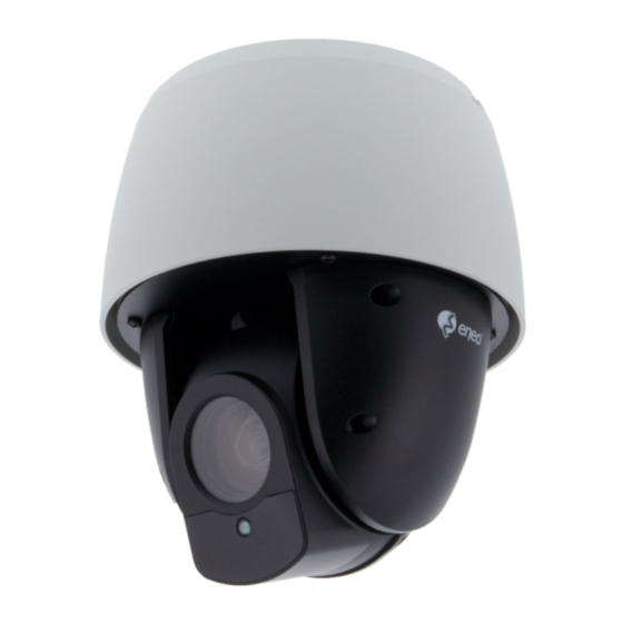
- Page 1 Quick Installation Guide 1/2.8” HD Dome, PTZ, Day&Night, 1920x1080, 20x, Infrared, 12VDC, IP66 MPP-72A0020MIA...
-
Page 2: Table Des Matières
Table of Contents Components........................5 Dimensions: mm ................................5 Mounting the Dome Camera ..................6 Locking the Dome Camera ...................7 Basic Configuration of Dome Camera System ......................8 Installation and Configuration ..................9 Setting the Camera ................................9 Setting the Dome Camera Address (ID) ......................... 10 Connections .................................. -
Page 3: General Safety Instructions
Safety instructions General safety instructions • Before switching on and operating the system, first read this safety advice and the operating instructions. • Keep the operating instructions in a safe place for later use. • Installation, commissioning and maintenance of the system may only be carried out by authorised individuals and in accordance with the installation instructions - ensuring that all applicable standards and guidelines are followed. -
Page 4: Graphical Symbols
Class A device note This is a Class A device. This device can cause malfunctions in the living area; in such an event, the operator may need to take appropriate measures to compensate for these. WEEE (Waste Electronical & Electronic Equipment) Correct Disposal of This Product (Applicable in the European Union and other European countries with separate collection systems). -
Page 5: Components
Components This system comes with the following components; • Dome Camera • Instruction Manual • Template Sheet • Mounting Bracket • Safety Lanyard • Accessory Kit • Accessory Connector Dimensions: mm... -
Page 6: Mounting The Dome Camera
Mounting the Dome Camera The dome camera is for use in surface or pendent mounting applications, and the mounting member must be capable of supporting loads of up to 10 lb (4.5 kg). (Pendent mounting must use pendent mount accessory.) The dome camera’s mounting bracket should be attached to a structural object, such as hard wood, wall stud or ceiling rafter that supports the weight of the dome camera. -
Page 7: Locking The Dome Camera
Locking the Dome Camera 1. Make screw holes on the ceiling using the supplied mounting Template Sheet (Figure A). 2. Fix the Mounting Bracket to the ceiling using supplied Anchors (4x) and Mounting Screws (4x) (Figure B). 3. Hook up the Safety Lanyard to the Safety Lanyard Hook of the Mounting Bracket (Figure C). -
Page 8: Basic Configuration Of Dome Camera System
CAUTION: Before installing mounting bracket to surface pre-adjust the four mounting screws “A” on the base of the dome camera to best match the mounting brack- et locked position. Unscrew the locking screw on the side of the dome’s base and fit the tab of the mounting bracket into the locking slot. -
Page 9: Installation And Configuration
Installation and Configuration Setting the Camera Open the DIP switch cover and change the setting of DIP switch. After changing the setting, close the cover tightly to ensure waterproofing. You can set video signal with D1 and video type with D2 in S1. S1-D1 Video Signal HD-TVI OUTPUT... -
Page 10: Setting The Dome Camera Address (Id)
You can set coaxitron protocol with D3 and D4 in S1. S1-D3 S1-D4 HD-TVI OUTPUT AHD OUTPUT Hikvision-C ACP-PTZ Pelco-C Reserved Reserved Reserved Reserved Reserved You can set CVBS output with D1 in S2. S2-D1 CVBS Output When WDR is on, CVBS output will be disabled. CVBS output will be displayed always. -
Page 11: Connecting Alarms
Connecting Alarms A1,A2,A3,A4 (Alarm Input 1,2,3,4) You can use external devices to signal the dome camera to react on events. Mechanical or electrical switches can be wired to the A1,A2,A3,A4 (Alarm Input 1,2,3,4) and G (Ground) connectors. GND (Ground) All the connectors marked G or GND are common. Connect the ground side of the alarm input and/or alarm output to the GND connector. -
Page 12: Program And Operation
Program and Operation Dome Camera Selection IF you use the keyboard, before you program or operate a dome camera, you must select the dome camera by pressing No. + CAM keys. Example: Pressing 1 , 0 + CAM keys sequentially will select dome camera 10. The selected dome camera ID will be displayed on the LCD monitor of the keyboard. -
Page 13: Further Information
Further information The manual is also available from the eneo web site at www.eneo-security.com. - Page 14 Inhaltsverzeichnis Komponenten ......................17 Abmessungen: mm ............................... 17 Befestigung der Dome-Kamera ..................18 Dome-Kamera verriegeln ...................19 Basiskonfiguration des Dome-Kamera-Systems ....................20 Installation und Konfiguration ...................21 Kameraeinstellungen ..............................21 Einstellung der Adresse (ID) der Dome-Kamera ....................22 Anschlüsse ..................................22 RS-485 Anschluss ..............................22 HD Anschluss verbinden ............................
-
Page 15: Sicherheitshinweise Allgemein
Sicherheitsanweisungen Sicherheitshinweise allgemein • Bevor Sie das System anschließen und in Betrieb nehmen, lesen Sie zuerst diese Sicherheitshinweise und die Betriebsanleitung. • Bewahren Sie die Betriebsanleitung sorgfältig zur späteren Verwendung auf. • Montage, Inbetriebnahme und Wartung des Systems darf nur durch dafür autorisierte Personen vorgenom- men und entsprechend den Installationsanweisungen - unter Beachtung aller mitgeltenden Normen und Richtlinien - durchgeführt werden. - Page 16 • Bei abgedunkelter Umgebung und direktem Blick in den IR-Scheinwerfer ist ein Sicherheitsabstand von > 1 m zum Scheinwerfer einzuhalten. • Unsichtbare LED Strahlung nicht direkt mit optischen Instrumenten (z.B. Lupe, Vergrößerungsglas oder Mikroskop) betrachten, da dies Augen gefährden kann, LED Klasse 1M. •...
-
Page 17: Komponenten
Komponenten Das System wird mit den folgenden Komponenten geliefert: • Dome-Kamera • Betriebsanleitung • Bohrschablone • Montagehalterung • Sicherheitskabel • Montageset • Steckverbindung Abmessungen: mm... -
Page 18: Befestigung Der Dome-Kamera
Befestigung der Dome-Kamera Die Dome-Kamera ist für den Einsatz in Anwendungen mit Aufbau- oder Abhängungs- montagen geeignet und das Befestigungselement muss Tragelasten bis 4,5 kg unterstüt- zen. (Für Abhängungsmontage wird Hängemontagezubehör benötigt). Die Montagehalterung der Dome-Kamera sollte an einem Bauelement, wie etwa Hartholz, einem Wandständer oder Deckenbalken, welches das Gewicht der Kamera trägt, befestigt werden. -
Page 19: Dome-Kamera Verriegeln
Dome-Kamera verriegeln 1. Bohren Sie die Löcher mit Hilfe der beiliegenden Schablone in die Decke (Abbil- dung A). 2. Befestigen Sie die Montagehalterung mit den beiliegenden Dübeln (4x) und Befestigungsschrauben (4x) an der Decke (Abbildung B). 3. Hängen Sie das Sicherheitskabel an den Haken an der Montagehalterung (Abbil- dung C). -
Page 20: Basiskonfiguration Des Dome-Kamera-Systems
ACHTUNG: Bevor Sie die Montagehalterung an der Oberfläche befestigen sollten Sie die Befestigungsschrauben "A" am Unterteil der Dome-Kamera vorjustieren damit Sie in der Verriegelungsposition optimal passen. Drehen Sie die Verriegelungsschraube an der Seite des Unterteil des Domes heraus und führen Sie die Lasche der Montagehalte- rung in den Verriegelungsschlitz. -
Page 21: Installation Und Konfiguration
Installation und Konfiguration Kameraeinstellungen Öffnen Sie die Abdeckung des DIP-Schalters, um die Einstellungen des DIP-Schalters zu ändern. Nachdem alle Einstellungen gemacht wurden, bringen Sie die Abdeckung wieder an und ziehen Sie diese fest, um die Wasserfestigkeit sicherzustellen. Das Videosignal kann mit D1 und das Videoformat mit D2 in SW1 eingestellt werden. S1-D1 Videosignal HD-TVI AUSGANG... -
Page 22: Einstellung Der Adresse (Id) Der Dome-Kamera
Das Coaxitron-Protokoll kann mit D3 und D4 in S1 eingestellt werden. S1-D3 S1-D4 HD-TVI AUSGANG AHD AUSGANG Hikvision-C ACP-PTZ Pelco-C Reserviert Reserviert Reserviert Reserviert Reserviert Der CVBS-Ausgang kann mit D1 und D2 eingestellt werden. S2-D1 FBAS-Ausgang Der FBAS-Ausgang ist deaktiviert, wenn die WDR- Funktion aktiviert ist. -
Page 23: Anschließen Von Alarmen
Anschließen von Alarmen A1, A2, A3, A4 (Alarmeingang 1, 2, 3, 4) Sie können externe Geräte anschließen, die der Dome-Kamera externe Ereignisse signali- sieren, damit sie auf diese reagiert. Mechanische oder elektrische Schalter können zwischen die Anschlüsse A1,A2,A3,A4 (Alarmeingang 1,2,3,4) und G (Masse) geschaltet werden. GND (Masse) Alle mit G oder GND gekennzeichneten Anschlüsse verfügen über eine gemeinsame Masse. -
Page 24: Programmierung Und Bedienung
Programmierung und Bedienung Dome-Kamera-Auswahl Bevor Sie die Dome-Kamera programmieren oder bedienen, müssen Sie sie durch Drü- cken der Tasten No. + CAM auf einer Steuerungstastatur auswählen. Beispiel: Aufeinander folgendes Drücken der Tasten1 , 0 + CAM wählt Dome-Kamera 10 aus. Die gewählte Kamera-ID wird auf dem LCD Bildschirm der Bedientastatur angezeigt. Zugriff auf das OSD-Menü... -
Page 25: Weitere Informationen
Weitere Informationen Dieses Handbuch ist auch auf der eneo-Webseite unter www.eneo-security.com verfügbar. - Page 26 Contenu Composants .........................29 Dimensions : mm ................................29 Montage de la caméra ....................30 Caméra dôme verrouillable ..................31 Configuration de base du système de caméra dôme ..................32 Installation et configuration ..................33 Installation de la caméra .............................. 33 Paramètres de l´adresse de la caméra dôme (ID) ....................34 Raccordements ................................
-
Page 27: Instructions De Sécurité
Instructions de sécurité Consignes de sécurité générales • Avant de brancher et de mettre en service le système, veuillez lire d'abord ces consignes de sécurité ainsi que la notice d'instructions. • Conservez soigneusement la notice d'instructions en vue d'une utilisation ultérieure. •... -
Page 28: Symboles Graphiques
• Une distance de sécurité > 1 m doit être respectée par rapport au projecteur dans un environnement sombre, quand on regarde directement dans le projecteur IR. • Les rayons invisibles des LED ne doivent pas être observés directement avec des instruments optiques (par ex. -
Page 29: Composants
Composants Le système est fourni avec les composants suivants : • Caméra dôme • Mode d’emploi • Gabarit de montage • Support de montage • Courroie de sécurité • Kit d'accessoires • Connecteur d'accessoires Dimensions : mm... -
Page 30: Montage De La Caméra
Montage de la caméra Le dôme est fait pour un montage en saillie ou encastré, à condition que l´ensemble de montage puisse supporter une charge max. de 4,5 kg. (Pour un montage en saillie, utiliser absolument les accessoires de fixation livrés.) Les supports de fixation de la caméra dôme doivent être fixés à... -
Page 31: Caméra Dôme Verrouillable
Caméra dôme verrouillable 1. Percer les trous au plafond au moyen des gabarits de montage (Figure A). 2. Fixer les supports de fixation en utilisant les chevilles (4x) et les vis de montage (4x) (Figure B). 3. Fixer les courroies de sécurité aux ergots de verrouillage des supports de fixation (Figure C). -
Page 32: Configuration De Base Du Système De Caméra Dôme
ATTENTION : Avant d´installer les supports de fixation, pré-ajuster les quatre vis de fixation "A" à la base du dôme pour avoir une position de verrouillage optimale. Dévis- ser la vis de blocage sur le côté du dôme et insérer l´ergot de verrouillage dans la fente de verrouillage. -
Page 33: Installation Et Configuration
Installation et configuration Installation de la caméra Ouvrez le couvercle de l'interrupteur DIP et modifiez le réglage de l'interrupteur DIP. Après avoir changé le réglage, fermez le couvercle fermement pour assurer l'étanchéité. Vous pouvez régler la sortie du signal vidéo avec le commutateur D1 et le type de vidéo avec D2 in S1. -
Page 34: Paramètres De L´adresse De La Caméra Dôme (Id)
Vous pouvez définir le protocole Coaxitron avec D3 et D4 dans S1. S1-D3 S1-D4 SORTIE HD-TVI SORTIE AHD Hikvision-C ACP-PTZ MARCHE Pelco-C Réservé MARCHE Réservé Réservé MARCHE MARCHE Réservé Réservé Vous pouvez définir la sortie CVBS avec D1 dans S2. S2-D1 Sortie CVBS Lorsque WDR est activé, la sortie CVBS sera désactivée. -
Page 35: Connexion Des Alarmes
Connexion des alarmes A1,A2,A3,A4 (entrée alarme 1,2,3,4) Vous pouvez utiliser des périphériques externes afin de demander à la caméra dôme de réagir aux événements. Les interrupteurs mécaniques ou électriques peuvent être reliés aux connecteurs A1,A2,A3,A4 (Entrées d´alarme 1,2,3,4) et GND (Terre). GND (Terre) Tous les connecteurs marqués G ou GND sont identiques. -
Page 36: Programme Et Fonctionnement
Programme et fonctionnement Sélection de la caméra dôme Si vous utilisez le clavier, Avant de programmer ou d´exploiter une caméra dôme, vous devez sélectionner la caméra dôme en appuyant sur No.+ touches CAM. Exemple : En appuyant sur 1 , 0 + touches CAM successivement, la caméra dôme sera sélectionnée en°10. -
Page 37: Complément D'information
Complément d'information Le manuel complet est également proposé sur le site Web d’eneo : www.eneo-security. com. - Page 38 Indice Componenti .........................41 Dimensioni: mm ................................41 Montaggio della telecamera..................42 Bloccaggio della telecamera dome ................43 Configurazione di base del sistema telecamera dome..................44 Installazione e configurazione ...................45 Impostazione della telecamera..........................45 Impostazione dell'indirizzo della telecamera dome (ID) ................. 46 Collegamenti ..................................
-
Page 39: Istruzioni Generali Per La Sicurezza
Istruzioni per la sicurezza Istruzioni generali per la sicurezza • Prima di collegare e mettere in funzione il sistema, leggete le istruzioni per la sicurezza e le istruzioni per l'uso. • Conservate con cura le istruzioni per l'uso per un eventuale utilizzo futuro. •... - Page 40 • Deve essere mantenuto un margine di sicurezza di > 1 m dal proiettore se si guarda direttamente nel proiettore IR in un ambiente buio. • Non guardare direttamente le radiazioni LED invisibili utilizzando strumenti ottici (ad es. lente, lente di ingrandimento o microscopio) per prevenire danni agli occhi ( LED classe 1M).
-
Page 41: Componenti
Componenti Il sistema viene fornito con i componenti seguenti: • Telecamera dome • Manuale di istruzioni • Dima • Staffa di montaggio • Cordino di sicurezza • Kit di accessori • Connettore di accessori Dimensioni: mm... -
Page 42: Montaggio Della Telecamera
Montaggio della telecamera La telecamera dome è destinata all'uso in applicazioni con installazione a muro o a so- spensione; l'elemento di installazione deve essere in grado di sostenere carichi fino a 4,5 kg. (per l'installazione a sospensione deve essere utilizzato l'accessorio per il montaggio a sospensione). -
Page 43: Bloccaggio Della Telecamera Dome
Bloccaggio della telecamera dome 1. Fare i buchi per le viti sul soffitto utilizzando la dima fornita (figura A). 2. Fissare la staffa di montaggio al soffitto utilizzando i tasselli (4x) e le viti di mon- taggio (4x) in dotazione (figura B). 3. -
Page 44: Configurazione Di Base Del Sistema Telecamera Dome
ATTENZIONE: prima di installare la staffa di montaggio pre-regolare le quattro viti di montaggio "A" alla base della telecamera dome adattandole il più possibile alla posizione di bloccaggio della staffa. Svitare la vite di bloccaggio a lato della base della telecamera dome e inserire la linguetta della staffa di montaggio nella fessura di bloccag- gio. -
Page 45: Installazione E Configurazione
Installazione e configurazione Impostazione della telecamera. Aprire la copertura del DIP switch e modificare l'impostazione dell'interruttore DIP. Al termine dell'imposta- zione, chiudere il coperchio di apertura e serrarlo per garantire la tenuta all'acqua. È possibile impostare il segnale video con D1 e il tipo di video con D2 in S1. Segnale S1-D1 video... -
Page 46: Impostazione Dell'indirizzo Della Telecamera Dome (Id)
Si può impostare il protocollo Coaxitron con D3 e D4 in S1. S1-D3 S1-D4 USCITA HD-TVI USCITA AHD Hikvision-C ACP-PTZ Pelco-C Riservato Riservato Riservato Riservato Riservato Si può impostare l'uscita CVBS con D1 in S2. S2-D1 Uscita CVBS Quando WDR è attivo, l'uscita CVBS sarà disabilitata. L'uscita CVBS verrà... -
Page 47: Collegamento Degli Allarmi
Collegamento degli allarmi A1,A2,A3,A4 (ingressi allarme 1,2,3,4) Si possono utilizzare dispositivi esterni per segnalare alla telecamera dome di reagire agli eventi. È possibile collegare interruttori meccanici o elettrici ai connettori A1, A2, A3, A4 (ingressi allarme 1, 2, 3, 4) e G (massa). GND (terra) Tutti i connettori marcati G o GND sono comuni. -
Page 48: Programmazione E Funzionamento
Programmazione e funzionamento Selezione della telecamera dome Se usi la tastiera, prima di programmare o utilizzare una telecamera dome è necessario selezionarla premendo i tasti N. + CAM. Esempio: premendo in sequenza i tasti 1, 0 + CAM si seleziona la telecamera dome 10. L'ID della telecamera dome selezionata viene visualizzato sul monitor LCD del controller tastiera. -
Page 49: Altre Informazioni
Altre informazioni Il manuale è disponibile anche sul sito web di eneo all'indirizzo www.eneo-security.com. - Page 52 VIDEOR E. Hartig GmbH Exclusive distribution through specialised trade channels only. VIDEOR E. Hartig GmbH Carl-Zeiss-Straße 8 63322 Rödermark/Germany Tel. +49 (0) 6074 / 888-0 Technical changes reserved Fax +49 (0) 6074 / 888-100 www.videor.com...